2021 FORD MUSTANG height
[x] Cancel search: heightPage 139 of 530
Tilting Head Restraints (If Equipped)
The front head restraints tilt for extra
comfort. To tilt the head restraint, do the
following: 1. Adjust the seatback to an upright
driving or riding position.
2. Pivot the head restraint forward toward
your head to the desired position.
After the head restraint reaches the
forward-most tilt position, pivoting it
forward again will then release it to the
rearward, un-tilted position.
MANUAL SEATS WARNING:
Do not adjust the
driver's seat or seatback when your
vehicle is moving. WARNING:
Rock the seat
backward and forward after releasing
the lever to make sure that it is fully
engaged. WARNING:
Reclining the seatback
can cause an occupant to slide under the
seat's safety belt, resulting in severe
personal injuries in the event of a crash.
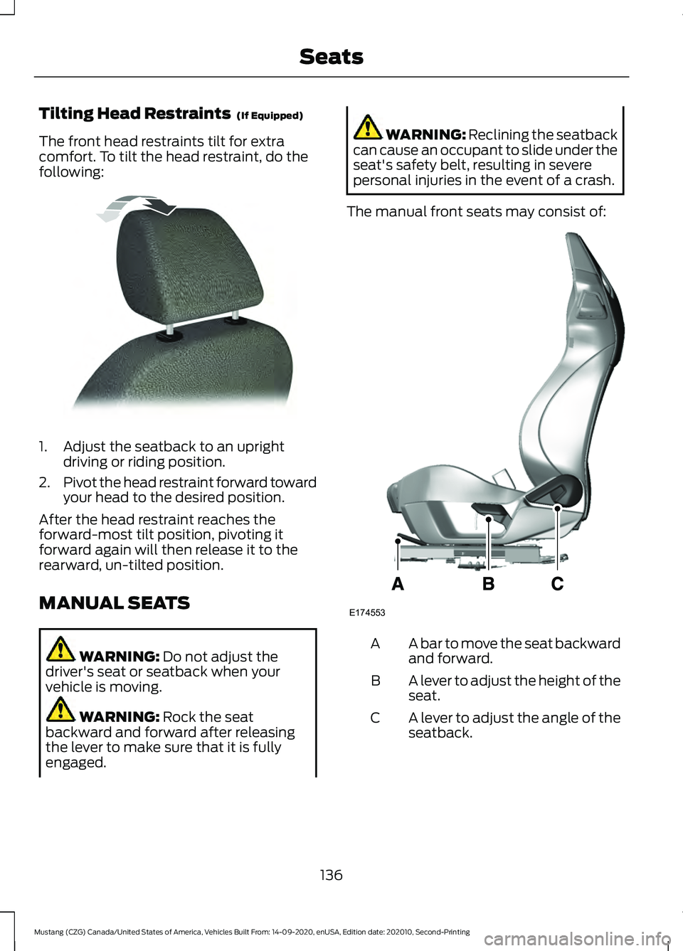
The manual front seats may consist of: A bar to move the seat backward
and forward.
A
A lever to adjust the height of the
seat.
B
A lever to adjust the angle of the
seatback.
C
136
Mustang (CZG) Canada/United States of America, Vehicles Built From: 14-09-2020, enUSA, Edition date: 202010, Second-Printing SeatsE144727 E174553
Page 276 of 530

Headlamp Aiming Target
8 ft (2.4 m).
A
Center height of lamp to ground.
B
25 ft (7.6 m).
C
Horizontal reference line.
D
Vertical Aim Adjustment
1. Park the vehicle directly in front of a wall or screen on a level surface,
approximately 25 ft (7.6 m) away.
2. Measure the height from the center of your headlamp indicated by a 3 mm
circle on the lens to the ground and
mark an
8 ft (2.4 m) horizontal
reference line on the vertical wall or
screen at this height, a piece of
masking tape works well.
Note: To see a clearer light pattern for
adjusting, you may want to block the light
from one headlamp while adjusting the
other.
3. Turn on the low beam headlamps to illuminate the wall or screen and open
the hood. Cover one of the headlamps
so no light hits the wall. 4. On the wall or screen you will observe
a flat zone of high intensity light at the
top of the right-hand portion of the
beam pattern. If the top edge of the
high intensity light zone is not at the
horizontal reference line, the headlamp
needs to be adjusted. 5. Locate the vertical adjuster on each
headlamp. Use a Phillips #2
screwdriver to turn the adjuster either
clockwise or counterclockwise to
adjust the vertical aim of the
headlamp.
6. Repeat Steps 3 through 7 to adjust the
other headlamp.
7. Close the hood and turn off the lamps.
273
Mustang (CZG) Canada/United States of America, Vehicles Built From: 14-09-2020, enUSA, Edition date: 202010, Second-Printing MaintenanceE142592 E142465 E250054
Page 293 of 530
Using a Two Post Vehicle Hoist
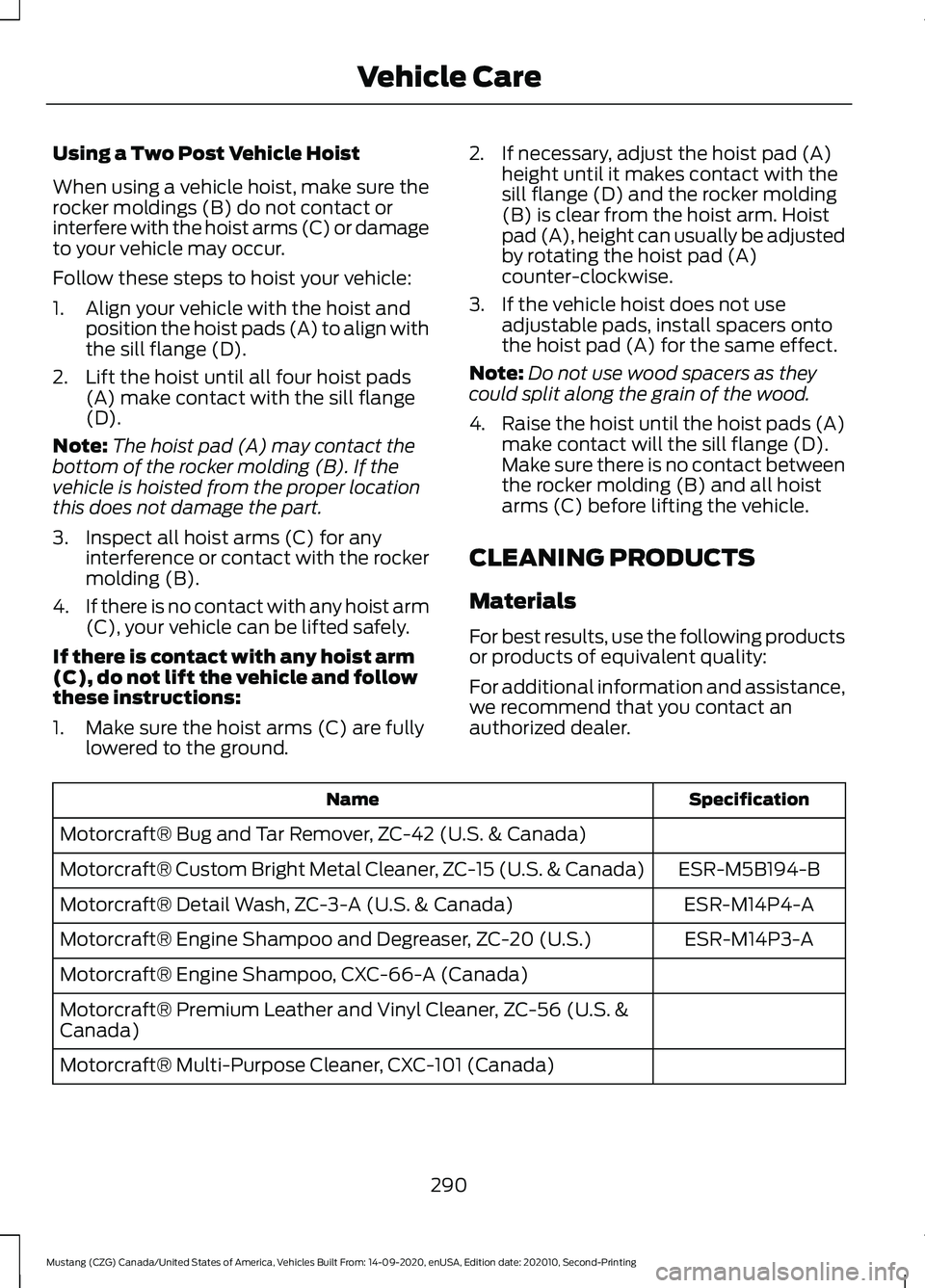
When using a vehicle hoist, make sure the
rocker moldings (B) do not contact or
interfere with the hoist arms (C) or damage
to your vehicle may occur.
Follow these steps to hoist your vehicle:
1. Align your vehicle with the hoist and
position the hoist pads (A) to align with
the sill flange (D).
2. Lift the hoist until all four hoist pads (A) make contact with the sill flange
(D).
Note: The hoist pad (A) may contact the
bottom of the rocker molding (B). If the
vehicle is hoisted from the proper location
this does not damage the part.
3. Inspect all hoist arms (C) for any interference or contact with the rocker
molding (B).
4. If there is no contact with any hoist arm
(C), your vehicle can be lifted safely.
If there is contact with any hoist arm
(C), do not lift the vehicle and follow
these instructions:
1. Make sure the hoist arms (C) are fully lowered to the ground. 2. If necessary, adjust the hoist pad (A)
height until it makes contact with the
sill flange (D) and the rocker molding
(B) is clear from the hoist arm. Hoist
pad (A), height can usually be adjusted
by rotating the hoist pad (A)
counter-clockwise.
3. If the vehicle hoist does not use adjustable pads, install spacers onto
the hoist pad (A) for the same effect.
Note: Do not use wood spacers as they
could split along the grain of the wood.
4. Raise the hoist until the hoist pads (A)
make contact will the sill flange (D).
Make sure there is no contact between
the rocker molding (B) and all hoist
arms (C) before lifting the vehicle.
CLEANING PRODUCTS
Materials
For best results, use the following products
or products of equivalent quality:
For additional information and assistance,
we recommend that you contact an
authorized dealer. Specification
Name
Motorcraft® Bug and Tar Remover, ZC-42 (U.S. & Canada) ESR-M5B194-B
Motorcraft® Custom Bright Metal Cleaner, ZC-15 (U.S. & Canada)
ESR-M14P4-A
Motorcraft® Detail Wash, ZC-3-A (U.S. & Canada)
ESR-M14P3-A
Motorcraft® Engine Shampoo and Degreaser, ZC-20 (U.S.)
Motorcraft® Engine Shampoo, CXC-66-A (Canada)
Motorcraft® Premium Leather and Vinyl Cleaner, ZC-56 (U.S. &
Canada)
Motorcraft® Multi-Purpose Cleaner, CXC-101 (Canada)
290
Mustang (CZG) Canada/United States of America, Vehicles Built From: 14-09-2020, enUSA, Edition date: 202010, Second-Printing Vehicle Care
Page 311 of 530
Information Contained on the
Tire Sidewall
Both United States and Canada
Federal regulations require tire
manufacturers to place
standardized information on the
sidewall of all tires. This
information identifies and
describes the fundamental
characteristics of the tire and also
provides a U.S. DOT Tire
Identification Number for safety
standard certification and in case
of a recall.
Information on P Type Tires
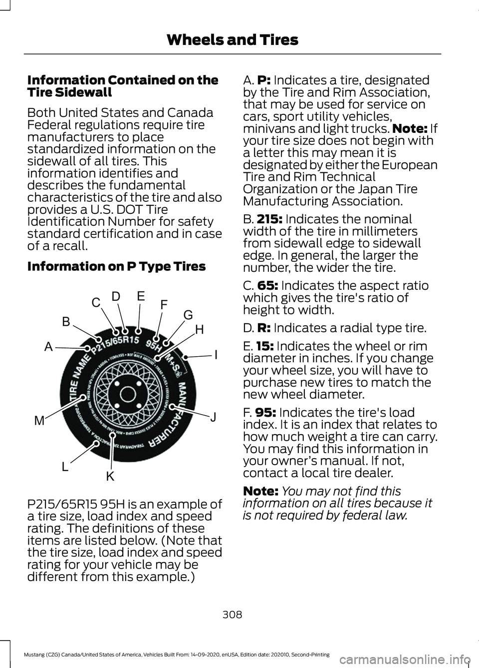
P215/65R15 95H is an example of
a tire size, load index and speed
rating. The definitions of these
items are listed below. (Note that
the tire size, load index and speed
rating for your vehicle may be
different from this example.) A.
P: Indicates a tire, designated
by the Tire and Rim Association,
that may be used for service on
cars, sport utility vehicles,
minivans and light trucks. Note:
If
your tire size does not begin with
a letter this may mean it is
designated by either the European
Tire and Rim Technical
Organization or the Japan Tire
Manufacturing Association.
B. 215:
Indicates the nominal
width of the tire in millimeters
from sidewall edge to sidewall
edge. In general, the larger the
number, the wider the tire.
C. 65:
Indicates the aspect ratio
which gives the tire's ratio of
height to width.
D. R:
Indicates a radial type tire.
E. 15:
Indicates the wheel or rim
diameter in inches. If you change
your wheel size, you will have to
purchase new tires to match the
new wheel diameter.
F. 95:
Indicates the tire's load
index. It is an index that relates to
how much weight a tire can carry.
You may find this information in
your owner ’s manual. If not,
contact a local tire dealer.
Note: You may not find this
information on all tires because it
is not required by federal law.
308
Mustang (CZG) Canada/United States of America, Vehicles Built From: 14-09-2020, enUSA, Edition date: 202010, Second-Printing Wheels and TiresH
I
J
KL
M
A
B
CDEFGE142543
Page 315 of 530
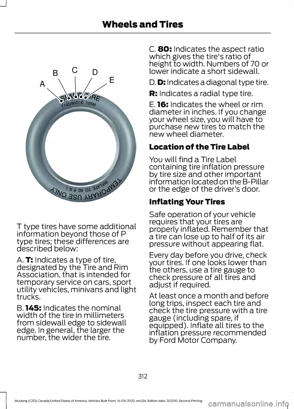
T type tires have some additional
information beyond those of P
type tires; these differences are
described below:
A.
T: Indicates a type of tire,
designated by the Tire and Rim
Association, that is intended for
temporary service on cars, sport
utility vehicles, minivans and light
trucks.
B. 145:
Indicates the nominal
width of the tire in millimeters
from sidewall edge to sidewall
edge. In general, the larger the
number, the wider the tire. C.
80:
Indicates the aspect ratio
which gives the tire's ratio of
height to width. Numbers of 70 or
lower indicate a short sidewall.
D. D:
Indicates a diagonal type tire.
R:
Indicates a radial type tire.
E. 16:
Indicates the wheel or rim
diameter in inches. If you change
your wheel size, you will have to
purchase new tires to match the
new wheel diameter.
Location of the Tire Label
You will find a Tire Label
containing tire inflation pressure
by tire size and other important
information located on the B-Pillar
or the edge of the driver ’s door.
Inflating Your Tires
Safe operation of your vehicle
requires that your tires are
properly inflated. Remember that
a tire can lose up to half of its air
pressure without appearing flat.
Every day before you drive, check
your tires. If one looks lower than
the others, use a tire gauge to
check pressure of all tires and
adjust if required.
At least once a month and before
long trips, inspect each tire and
check the tire pressure with a tire
gauge (including spare, if
equipped). Inflate all tires to the
inflation pressure recommended
by Ford Motor Company.
312
Mustang (CZG) Canada/United States of America, Vehicles Built From: 14-09-2020, enUSA, Edition date: 202010, Second-Printing Wheels and TiresA
BCDEE142545
Page 318 of 530
Inspecting Your Tires and
Wheel Valve Stems
Periodically inspect the tire treads
for uneven or excessive wear and
remove objects such as stones,
nails or glass that may be wedged
in the tread grooves. Check the tire
and valve stems for holes, cracks,
or cuts that may permit air
leakage and repair or replace the
tire and replace the valve stem.
Inspect the tire sidewalls for
cracking, cuts, bruises and other
signs of damage or excessive
wear. If internal damage to the tire
is suspected, have the tire
demounted and inspected in case
it needs to be repaired or replaced.
For your safety, tires that are
damaged or show signs of
excessive wear should not be used
because they are more likely to
blow out or fail.
Improper or inadequate vehicle
maintenance can cause tires to
wear abnormally. Inspect all your
tires, including the spare,
frequently, and replace them if
one or more of the following
conditions exist:
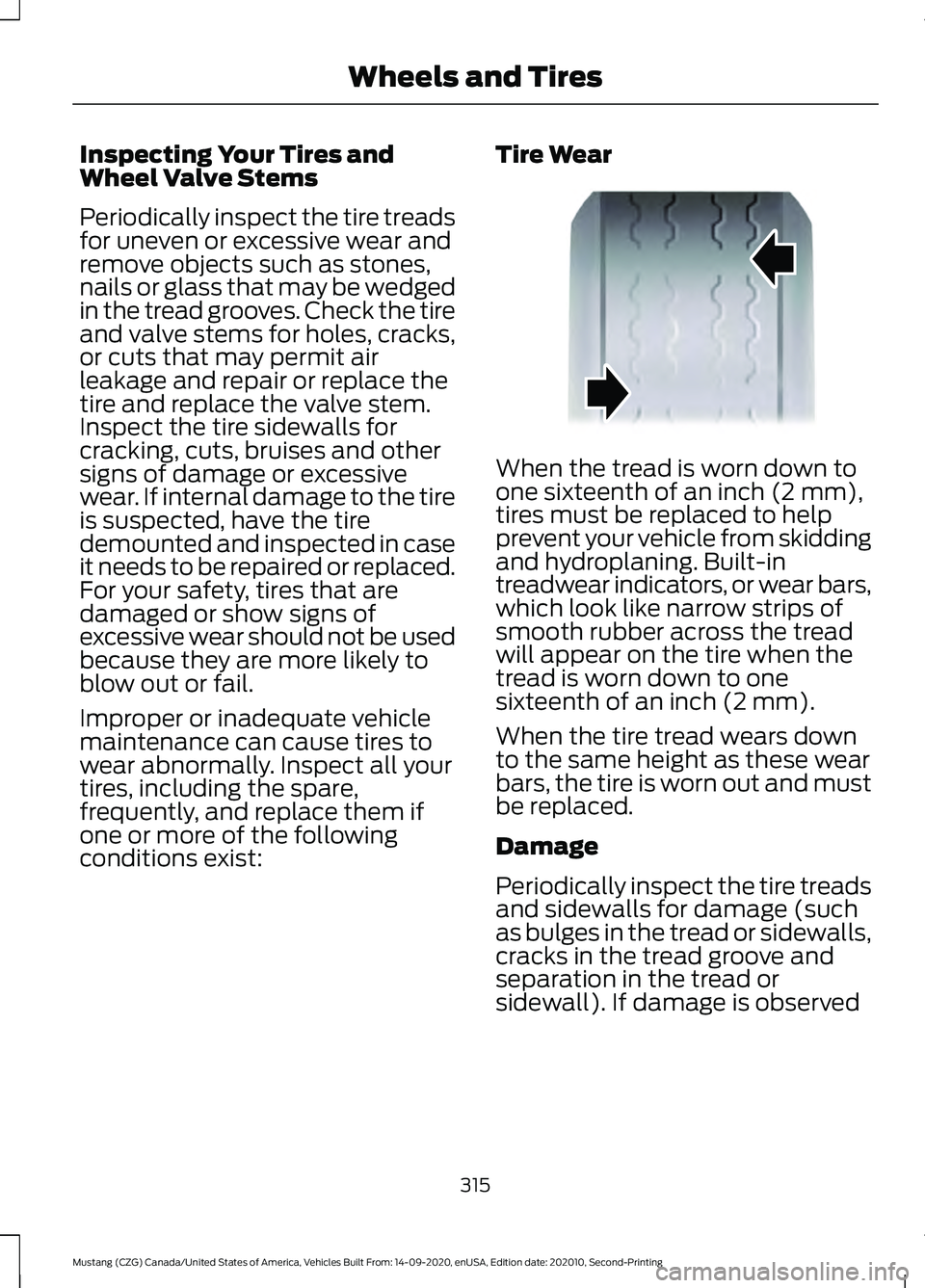
Tire Wear When the tread is worn down to
one sixteenth of an inch (2 mm),
tires must be replaced to help
prevent your vehicle from skidding
and hydroplaning. Built-in
treadwear indicators, or wear bars,
which look like narrow strips of
smooth rubber across the tread
will appear on the tire when the
tread is worn down to one
sixteenth of an inch (2 mm).
When the tire tread wears down
to the same height as these wear
bars, the tire is worn out and must
be replaced.
Damage
Periodically inspect the tire treads
and sidewalls for damage (such
as bulges in the tread or sidewalls,
cracks in the tread groove and
separation in the tread or
sidewall). If damage is observed
315
Mustang (CZG) Canada/United States of America, Vehicles Built From: 14-09-2020, enUSA, Edition date: 202010, Second-Printing Wheels and TiresE142546
Page 335 of 530

8. Loosen each wheel lug nut one-half
turn counterclockwise but do not
remove them until the wheel is raised
off the ground. Note:
Jack at the specified locations to
avoid damage to the vehicle.
9. The vehicle jacking points are shown here, and can be identified by the
triangle markings on the vehicle. Details
are depicted on the warning label on
the jack. 10. Place the jack at the jacking point
next to the tire you are changing. Turn
the jack handle clockwise until the
wheel is completely off the ground. 11. Remove the lug nuts with the lug
wrench.
12. Replace the flat tire with the spare tire, making sure the valve stem is
facing outward. Reinstall lug nuts
until the wheel is snug against the
hub. Do not fully tighten the lug nuts
until the wheel has been lowered. If
you are using the temporary tire, the
lug nut washers do not appear to be
flush with the rim. This is normal only
when using the temporary spare tire.
13. Lower the wheel by turning the jack handle counterclockwise. 14.
Remove the jack and fully tighten the
lug nuts in the order shown. See
Technical Specifications (page
334).
15. To store the folded wrench on the jack, engage the bracket of the jack
base on the wrench feature as shown.
Swing the wrench upwards and
adjust the height of the jack until the
pin engages the hole. Tighten the hex
nut clockwise by hand until secure.
332
Mustang (CZG) Canada/United States of America, Vehicles Built From: 14-09-2020, enUSA, Edition date: 202010, Second-Printing Wheels and TiresE176084 E174939 12
3
4
5E306781