2021 FORD F650/750 automatic
[x] Cancel search: automaticPage 128 of 390

To prevent the engine from running at too
low an RPM, which could cause it to stall,
SelectShift still makes some downshifts
if it has determined that you have not
downshifted in time. Although SelectShift
makes some downshifts for you, it still
allows you to downshift at any time if the
SelectShift determines there is no damage
to the engine from over-revving.
SelectShift does not automatically upshift,
even if the engine is approaching the RPM
limit. Shift manually by pressing the +
button.
Note:
Engine damage could occur if you rev
the engine excessively and hold it without
shifting.
Progressive Range Selection - PRS
(If Equipped)
Progressive Range Selection gives you the
ability to lockout gears from the automatic
shifting range. This could provide you with
an improved driving experience, for
example, in slippery conditions or when
experiencing a steep slope.
With the gearshift lever in drive (D), press
the – button to activate progressive range
selection. The instrument cluster indicates
the available and selected gears.
All available gears display with the current
gear indicated. Press the – button again to
lock out gears beginning with the highest
gear. For example, press the – button twice
to lock out sixth (6) and fifth (5) gears.
Only the available gears display, and the
transmission shifts between the available
gears. Press the + button to unlock gears
to allow the transmission to shift to higher
gears. The transmission shifts within the
gear range you select. Automatic Transmission Adaptive
Learning
This feature could increase durability and
provide consistent shift feel over the life
of your vehicle. A new vehicle or
transmission may have firm shifts, soft
shifts, or both. This is normal and does not
affect the function or durability of the
transmission. Over time, the adaptive
learning process fully updates transmission
operation.
Brake-Shift Interlock
WARNING: Do not drive your
vehicle until you verify that the
stoplamps are working. WARNING:
When doing this
procedure, you need to take the
transmission out of park (P) which
means your vehicle can roll freely. To
avoid unwanted vehicle movement,
always fully apply the parking brake prior
to doing this procedure. Use wheels
chocks if appropriate. WARNING:
If the parking brake is
fully released, but the brake warning
lamp remains illuminated, the brakes
may not be working properly. Have your
vehicle checked as soon as possible.
Your vehicle has a feature that prevents
the gearshift lever from moving from park
(P) when you switch the ignition on but
you are not pressing on the brake pedal.
If you cannot move the gearshift lever out
of the park (P) position with the ignition in
the on position and the brake pedal
pressed, a malfunction could have
occurred. It is possible that a fuse has
blown, or your vehicle ’s brake lamps are
not operating properly.
See Fuse
Specification Chart (page 193).
125
F650750 (TBC) , enUSA, Edition date: 202010, Second-Printing Transmission
Page 131 of 390

GENERAL INFORMATION
WARNING: Exceeding these ratings
by overloading can cause component
failure resulting in property damage,
personal injury or death.
Fluid Temperature
If the operating temperature exceeds
250°F (121°C), the rate of axle lubrication
oxidation increases and shortens the life
of the lubricant and seals, requiring axle
lubrication changes to become more
frequent to preserve the axle. Do not
consistently run extreme pressure (EP)
lubricants above
250°F (121°C).
Axle Conversions WARNING:
When operating a
loaded vehicle, the driver must keep all
adjustable axles on the ground at all
times, supporting their share of the
vehicle ’s load. Failure to do so can
overload other axles, tires, wheels,
springs, steering components, brakes
and frames, resulting in early component
failure, loss of vehicle control, possible
property damage and personal injury.
We do not recommend, or approve,
performing axle conversions. However, we
understand that, on occasion, others install
aftermarket add-on axles on the truck
chassis that allow operator control for
weight transfer from other axles (such as
air lift axles). ELECTRONIC LOCKING
DIFFERENTIAL
(IF EQUIPPED)
Driver-Controlled Electronic
Locking Differential
Note: Never use the differential lock at
vehicle speeds above
25 mph (40 km/h).
Some drive axles have a driver-controlled
differential lock. The differential lock can
lock or unlock the differential when your
vehicle is moving or stopped. When you
require extra traction, the differential lock
provides full power to both wheels.
When you lock the differential, your
vehicle ’s turning radius increases
(under-steer).
Take care to avoid sudden accelerations
when both drive wheels are on a slippery
surface. WARNING:
Sudden acceleration
on slippery surfaces could cause the
wheels to spin, the vehicle to turn
sideways on a crowned road surface or
in a turn, possibly resulting in loss of
vehicle control and personal injury.
Activating the Electronic Locking
Differential
You can lock and unlock the differential
when your vehicle is moving at a constant
speed of less than 25 mph (40 km/h) and
while the wheels are not slipping. Do not
lock the differential when your vehicle is
traveling down steep grades and when
traction is minimal.
The differential lock and differential lock
light automatically disengage at speeds
above
25 mph (40 km/h). The differential
lock remains off until either you restart your
vehicle, or you turn the differential lock
switch off then back on.
128
F650750 (TBC) , enUSA, Edition date: 202010, Second-Printing Rear Axle
Page 133 of 390

GENERAL INFORMATION
WARNING: Do not apply the brake
pedal and accelerator pedal
simultaneously. Applying both pedals
simultaneously for more than a few
seconds will limit engine performance,
which may result in difficulty maintaining
speed in traffic and could lead to serious
injury.
Note: Occasional brake noise is normal. If
a metal-to-metal, continuous grinding or
continuous squeal sound is present, the
brake linings may be worn-out. Have the
system checked as soon as possible. If your
vehicle has continuous vibration or shudder
in the steering wheel while braking, have it
checked by an authorized dealer.
All standard equipment brakes are
self-adjusting. Automatic adjustment,
when required, occurs whenever you apply
and release the brakes during forward or
reverse operation.
Know the required stopping distances for
all driving conditions you may encounter.
For longer brake lining life, take full
advantage of engine braking power when
coming to a stop.
Wet brakes result in reduced braking
efficiency. Gently press the brake pedal a
few times when driving from a car wash or
standing water to dry the brakes.
If the brakes do not grip well:
• Check brake adjustment.
• Check the brake linings for excessive
wear.
• Check the system air pressure on
vehicles with air brakes. •
Let the brakes cool if you have been
using them excessively, as in mountain
driving or after several fast, high-speed
stops.
• If you have been driving through deep
water, gently apply the brakes several
times while your vehicle is moving
slowly.
Brake Over Accelerator
In the event the accelerator pedal
becomes stuck or entrapped, apply steady
and firm pressure to the brake pedal to
slow the vehicle and reduce engine power.
If you experience this condition, apply the
brakes and bring your vehicle to a safe
stop. Move the transmission to park (P),
switch the engine off and apply the parking
brake. Inspect the accelerator pedal for
any interference. If none are found and the
condition persists, have your vehicle towed
to the nearest authorized dealer
Anti-lock Brake System
This system helps you maintain steering
control during emergency stops by keeping
the brakes from locking. This lamp momentarily
illuminates when you switch the
ignition on. If the light does not
illuminate during start up, remains on or
flashes, the system may be disabled. Have
the system checked by an authorized
dealer. If you connect a PLC trailer with
the ignition on, the trailer ABS
light also illuminates. If the light
fails to illuminate, if it remains on after you
start the vehicle or continues to flash, have
the system serviced immediately.
See
Warning Lamps and Indicators
(page 66).
130
F650750 (TBC) , enUSA, Edition date: 202010, Second-Printing Brakes E210335
Page 137 of 390
5. Tighten the nut until the spring is fully
caged and brakes released. Do not
loosen or remove the release stud and
nut unless you completely assemble
and securely clamp the brake chamber.
6. After restoring the air pressure, unscrew and remove the release stud
and install in the carrying pocket. Install
the access plug.
HILL START ASSIST WARNING: The system does not
replace the parking brake. When you
leave your vehicle, always apply the
parking brake. WARNING:
You must remain in
your vehicle when the system turns on.
At all times, you are responsible for
controlling your vehicle, supervising the
system and intervening, if required.
Failure to take care may result in the loss
of control of your vehicle, serious
personal injury or death. WARNING:
The system will turn
off if a malfunction is apparent or if you
rev the engine excessively. Failure to take
care may result in the loss of control of
your vehicle, serious personal injury or
death.
The system makes it easier to pull away
when your vehicle is on a slope without the
need to use the parking brake.
When the system is active, your vehicle
remains stationary on the slope for two to
three seconds after you release the brake
pedal. This allows time to move your foot
from the brake to the accelerator pedal.
The system releases the brakes
automatically once the engine has developed sufficient torque to prevent your
vehicle from rolling down the slope. This
is an advantage when pulling away on a
slope, for example from a car park ramp,
traffic lights or when reversing uphill into
a parking space.
The system activates on any slope that
causes your vehicle to roll.
Note:
There is no warning light to indicate
the system is either on or off.
Using Hill Start Assist
1. Press the brake pedal to bring your vehicle to a complete standstill. Keep
the brake pedal pressed and shift into
first gear when facing uphill or reverse
(R) when facing downhill.
2. If the sensors detect that your vehicle is on a slope, the system activates
automatically.
3. When you remove your foot from the brake pedal, your vehicle remains on
the slope without rolling away for
about two to three seconds. This hold
time automatically extends if you are
in the process of driving off.
4. Drive off in the normal manner. The system releases the brakes
automatically.
Note: When you remove your foot from the
brake pedal and press the pedal again when
the system is active, you will experience
significantly reduced brake pedal travel. This
is normal.
Switching the System On and Off
Vehicles with Manual Transmission
You can switch this feature on or off in the
information display. The system
remembers the last setting when you start
your vehicle.
134
F650750 (TBC) , enUSA, Edition date: 202010, Second-Printing Brakes
Page 138 of 390

Vehicles with Automatic Transmission
You cannot turn the system on or off.
When you switch the ignition on, the
system automatically turns on.
AIR BRAKES (IF EQUIPPED)
WARNING: Do not drive or continue
to drive if the low air pressure buzzer is
sounding or the brake warning light is lit.
These warnings indicate that air pressure
is not to normal operating level.
Continued use of the vehicle could result
in loss of braking ability. WARNING:
Avoid repeated light
application of the brake pedal. This
depletes air pressure faster and could
result in loss of braking capability. WARNING:
Do not move the
vehicle when the air pressure is
insufficient because the brake system
may be inoperative.
After starting the engine, give the air
compressor time to build up the air
pressure to
60 psi (414 kPa) before moving
your vehicle. Periodically check the air pressure gauge
while driving. Pressure should range
between approximately 100 psi (690 kPa)
to
130 psi (896 kPa). The air compressor
governor cut-in and cutout pressure
settings are set at the factory and are not
adjustable. When air pressure is insufficient
(below
60 psi (414 kPa)), a
warning light illuminates and a
buzzer sounds when the ignition is in the
on position. This may happen because
excessive brake applications are depleting
the system air pressure. If this condition
occurs, stop driving your vehicle until the
compressor has fully recharged the air
system.
Select a gear ratio to help slow your vehicle
before descending grades. Supplementing
with brakes, as required, help to safely slow
the vehicle and avoids overspeeding the
engine.
Air Chamber Stroke Indication
Air chamber push rods have orange stroke
indicator markers that warn when the
braking system requires adjustment or
repair. The painted orange indicator is on
the air chamber push rod at the slack
adjuster stroke dimension that requires
service when visible during brake
application.
A qualified service technician should
perform air brake inspection and
adjustment or repairs keeping to the
instructions in the service manual.
135
F650750 (TBC) , enUSA, Edition date: 202010, Second-Printing BrakesE210336 E206772
Page 139 of 390
Cam Brakes - Automatic Slack
Adjusters
WARNING: Do not manually adjust
the automatic slack adjusters to correct
excessive push rod stroke as it may result
in reduced brake effectiveness and a
vehicle crash. Excessive push rod stroke
indicates that a problem exists with the
automatic adjuster, with the installation
of the adjuster, or with foundation brake
components that manual adjustment
does not remedy. Seek service from a
qualified facility for excessive push rod
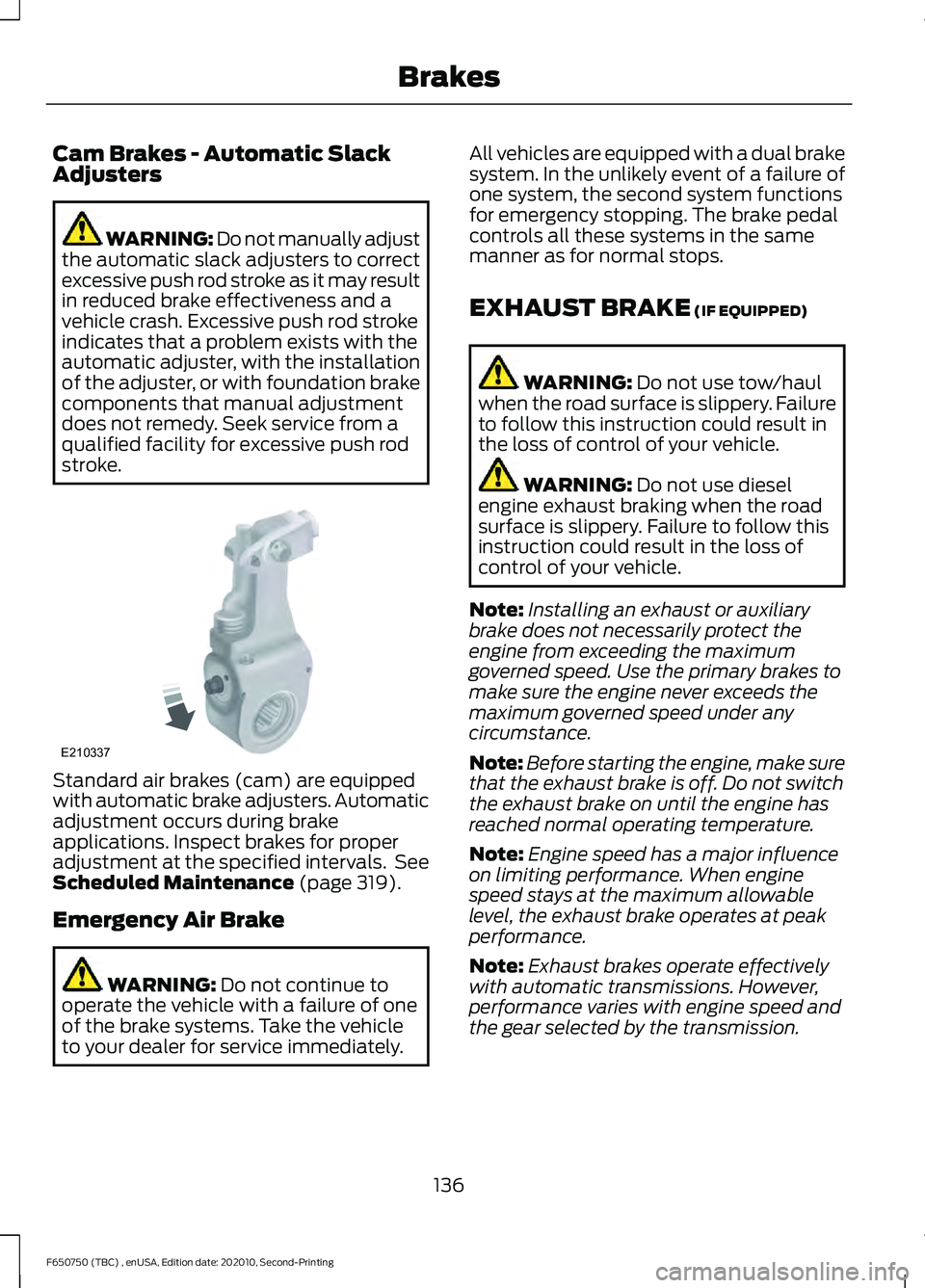
stroke. Standard air brakes (cam) are equipped
with automatic brake adjusters. Automatic
adjustment occurs during brake
applications. Inspect brakes for proper
adjustment at the specified intervals. See
Scheduled Maintenance (page 319).
Emergency Air Brake WARNING:
Do not continue to
operate the vehicle with a failure of one
of the brake systems. Take the vehicle
to your dealer for service immediately. All vehicles are equipped with a dual brake
system. In the unlikely event of a failure of
one system, the second system functions
for emergency stopping. The brake pedal
controls all these systems in the same
manner as for normal stops.
EXHAUST BRAKE
(IF EQUIPPED)
WARNING:
Do not use tow/haul
when the road surface is slippery. Failure
to follow this instruction could result in
the loss of control of your vehicle. WARNING:
Do not use diesel
engine exhaust braking when the road
surface is slippery. Failure to follow this
instruction could result in the loss of
control of your vehicle.
Note: Installing an exhaust or auxiliary
brake does not necessarily protect the
engine from exceeding the maximum
governed speed. Use the primary brakes to
make sure the engine never exceeds the
maximum governed speed under any
circumstance.
Note: Before starting the engine, make sure
that the exhaust brake is off. Do not switch
the exhaust brake on until the engine has
reached normal operating temperature.
Note: Engine speed has a major influence
on limiting performance. When engine
speed stays at the maximum allowable
level, the exhaust brake operates at peak
performance.
Note: Exhaust brakes operate effectively
with automatic transmissions. However,
performance varies with engine speed and
the gear selected by the transmission.
136
F650750 (TBC) , enUSA, Edition date: 202010, Second-Printing BrakesE210337
Page 141 of 390
•
A drop in engine RPM, depending on
grade and vehicle load, during a
descent.
• A decrease in road speed when
applying the exhaust brake during a
descent, except when your vehicle is
carrying a heavy load or the grade is
extremely steep. In these instances,
you may need to apply the service
brakes occasionally.
TRAILER BRAKES
Trailer Brake Hand Control (If Equipped) WARNING: The hand control
should never be used to apply the brakes
when the tractor and trailer are parked
unattended. Air may leak from the
system and the vehicle could possibly
move, resulting in possible property
damage, personal injury or death. The hand control is located on the
right-hand side of the instrument panel. It
applies the trailer service brakes, which are
independent of the truck or tractor service
brakes.
It operates a valve that provides gradual
control of air pressure applied. When the
valve is only partially applied, you can
override the trailer brakes by pressing fully
on the brake pedal. To apply the trailer brakes using the hand
control, move the lever downward. The
further you push the lever down, the
greater the air pressure is applied to the
brakes. The lever remains in place until
manually moved.
To release the trailer brakes, move the
lever up completely.
Trailer Air Supply and Parking
Brake Modular Controls
(If Equipped)
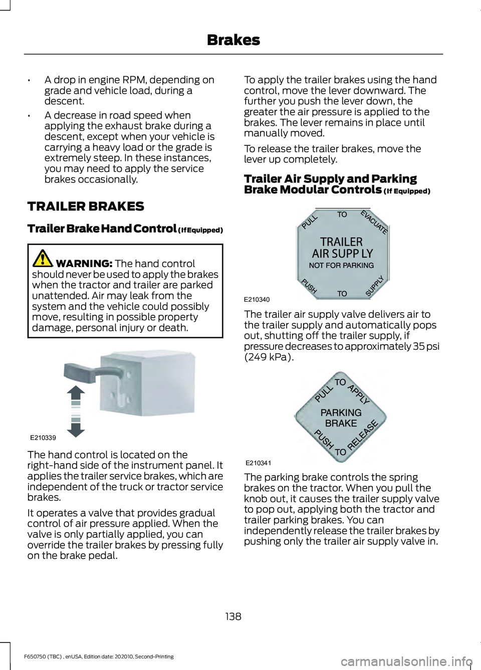
The trailer air supply valve delivers air to
the trailer supply and automatically pops
out, shutting off the trailer supply, if
pressure decreases to approximately 35 psi
(249 kPa)
.
The parking brake controls the spring
brakes on the tractor. When you pull the
knob out, it causes the trailer supply valve
to pop out, applying both the tractor and
trailer parking brakes. You can
independently release the trailer brakes by
pushing only the trailer air supply valve in.
138
F650750 (TBC) , enUSA, Edition date: 202010, Second-Printing BrakesE210339 E210340
A
B
12
A320
A E210341
Page 144 of 390
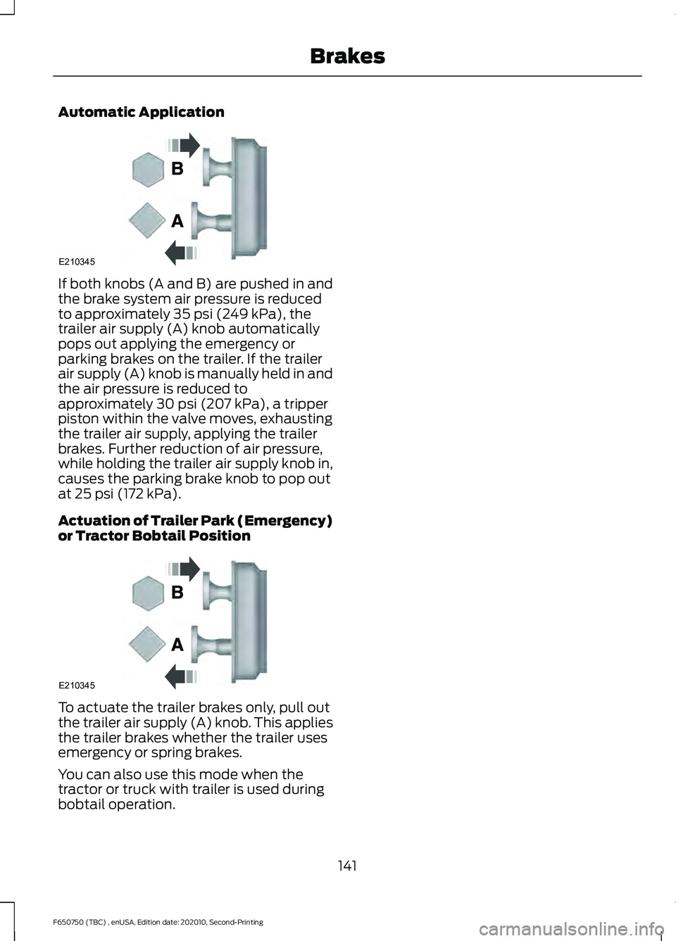
Automatic Application
If both knobs (A and B) are pushed in and
the brake system air pressure is reduced
to approximately 35 psi (249 kPa), the
trailer air supply (A) knob automatically
pops out applying the emergency or
parking brakes on the trailer. If the trailer
air supply (A) knob is manually held in and
the air pressure is reduced to
approximately
30 psi (207 kPa), a tripper
piston within the valve moves, exhausting
the trailer air supply, applying the trailer
brakes. Further reduction of air pressure,
while holding the trailer air supply knob in,
causes the parking brake knob to pop out
at
25 psi (172 kPa).
Actuation of Trailer Park (Emergency)
or Tractor Bobtail Position To actuate the trailer brakes only, pull out
the trailer air supply (A) knob. This applies
the trailer brakes whether the trailer uses
emergency or spring brakes.
You can also use this mode when the
tractor or truck with trailer is used during
bobtail operation.
141
F650750 (TBC) , enUSA, Edition date: 202010, Second-Printing BrakesE210345 E210345