2021 FORD F650/750 power steering
[x] Cancel search: power steeringPage 233 of 390
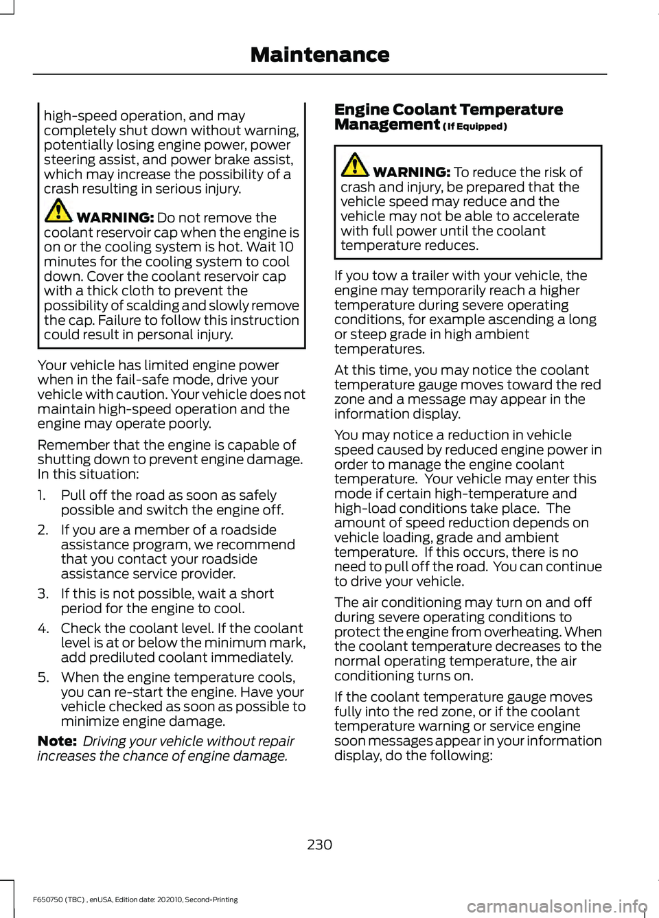
high-speed operation, and may
completely shut down without warning,
potentially losing engine power, power
steering assist, and power brake assist,
which may increase the possibility of a
crash resulting in serious injury.
WARNING: Do not remove the
coolant reservoir cap when the engine is
on or the cooling system is hot. Wait 10
minutes for the cooling system to cool
down. Cover the coolant reservoir cap
with a thick cloth to prevent the
possibility of scalding and slowly remove
the cap. Failure to follow this instruction
could result in personal injury.
Your vehicle has limited engine power
when in the fail-safe mode, drive your
vehicle with caution. Your vehicle does not
maintain high-speed operation and the
engine may operate poorly.
Remember that the engine is capable of
shutting down to prevent engine damage.
In this situation:
1. Pull off the road as soon as safely possible and switch the engine off.
2. If you are a member of a roadside assistance program, we recommend
that you contact your roadside
assistance service provider.
3. If this is not possible, wait a short period for the engine to cool.
4. Check the coolant level. If the coolant level is at or below the minimum mark,
add prediluted coolant immediately.
5. When the engine temperature cools, you can re-start the engine. Have your
vehicle checked as soon as possible to
minimize engine damage.
Note: Driving your vehicle without repair
increases the chance of engine damage. Engine Coolant Temperature
Management
(If Equipped) WARNING:
To reduce the risk of
crash and injury, be prepared that the
vehicle speed may reduce and the
vehicle may not be able to accelerate
with full power until the coolant
temperature reduces.
If you tow a trailer with your vehicle, the
engine may temporarily reach a higher
temperature during severe operating
conditions, for example ascending a long
or steep grade in high ambient
temperatures.
At this time, you may notice the coolant
temperature gauge moves toward the red
zone and a message may appear in the
information display.
You may notice a reduction in vehicle
speed caused by reduced engine power in
order to manage the engine coolant
temperature. Your vehicle may enter this
mode if certain high-temperature and
high-load conditions take place. The
amount of speed reduction depends on
vehicle loading, grade and ambient
temperature. If this occurs, there is no
need to pull off the road. You can continue
to drive your vehicle.
The air conditioning may turn on and off
during severe operating conditions to
protect the engine from overheating. When
the coolant temperature decreases to the
normal operating temperature, the air
conditioning turns on.
If the coolant temperature gauge moves
fully into the red zone, or if the coolant
temperature warning or service engine
soon messages appear in your information
display, do the following:
230
F650750 (TBC) , enUSA, Edition date: 202010, Second-Printing Maintenance
Page 241 of 390

1. Park your vehicle on a level surface.
2. Look at the brake fluid reservoir to see
where the brake fluid level is relative
to the MIN and the MAX marks on the
reservoir.
Note: If the brake fluid level is between the
MIN
and the MAX marks on the reservoir, it
is acceptable.
Note: If the brake fluid level is below the
MIN
mark or above the MAX mark, have
your vehicle checked as soon as possible.
Note: To avoid fluid contamination, the
reservoir cap must remain in place and fully
tight, unless you are adding fluid.
Only use fluid that meets our
specifications. See
Capacities and
Specifications (page 281).
Brake Fluid Service Interval
Brake fluid absorbs water over time which
degrades the effectiveness of the brake
fluid. Change the brake fluid at the
specified intervals to prevent degraded
braking performance. For detailed interval information, see
Scheduled Maintenance in your Owner's
Manual or your local maintenance guide.
POWER STEERING FLUID
CHECK
Check the power steering fluid. See
Scheduled Maintenance
(page 319). If
adding fluid is necessary, use only
MERCON LV ATF
Check the fluid level when it is at ambient
temperature.
1. Check the fluid level in the reservoir. It should be between the MIN and MAX
range. Do not add fluid if the level is
within this range.
2. If the fluid level is low, add fluid to bring
the fluid level up to between the MIN
and MAX range.
3. Switch the engine on.
4. While the engine idles, turn the steering
wheel left and right several times.
5. Switch the engine off.
6. Recheck the fluid level in the reservoir. Do not add fluid if the level is between
the MIN and MAX range.
7. If the fluid is low, add the proper type of fluid in small amounts, continuously
checking the level until it is between
the MIN and MAX range. See
Capacities and Specifications (page
288). Be sure to put the cap back on the
reservoir.
238
F650750 (TBC) , enUSA, Edition date: 202010, Second-Printing MaintenanceE170684
Page 255 of 390

Follow the tire manufacturer's
recommended cold inflation pressure for
the tire size, load range (ply rating) and
steer axle loading typical for their operation
(each steer axle tire equals ½ steer axle
loading).
Special applications may warrant a setting
based on experience with the type of tire
operating loads and conditions. Radial tires
are more sensitive to toe-in setting than
bias ply tires. Fine tuning school bus
alignment to line-haul truck standards
does not drastically improve tire tread life.
STEERING SYSTEM
INSPECTION
WARNING: Failure to maintain the
steering system in proper condition can
cause reduced steering ability resulting
in property damage, personal injury or
death.
Note: Have any steering problems
immediately corrected by a qualified service
technician.
Ask your service technician to examine the
steering mechanism. Only minor
adjustments may be necessary.
Regular inspections should include:
• Checking the tie rod, drag link end
clamp bolts and ball joints for proper
tightness.
• Checking for installation and spread of
cotter pins and tightness of nuts at
both ends of the tie rod and drag link.
• Checking that the pitman arm (steering
arm at steering gear) mounting is tight
and locked. Check system for leaks or
hose chafing. Repair immediately, if
necessary. •
Maintaining proper steering gear and
power steering pump lubricant levels.
• Checking steering column joint bolts
and steering linkage, particularly for
body-to-chassis clearance.
Steering Column Joint Bolts
As a good maintenance practice, check
steering column joint bolt tightness every
60,000 mi (96,000 km)
or annually,
whichever occurs first. Do not overtighten
the bolts.
Hydraulic System
Whenever draining and refilling the power
steering's hydraulic system for any reason,
bleed air from the system before returning
the vehicle to service. Failure to bleed the
hydraulic system properly can result in
degradation of power system performance.
Consult an authorized dealer who is aware
of the proper procedures for filling and
bleeding the system.
SUSPENSION SYSTEM
INSPECTION
Note: Do not adjust air suspension height
to any setting other than the specified
setting. Altering the height setting changes
the driveline angle and may result in
unwarrantable component damage, such
as transmission component damage.
Verify drive axle air suspension height and
height control valve performance at engine
oil change intervals.
Periodically check:
• Condition of spring leaves for evidence
of fatigue, bending or breakage.
• Condition of suspension mounting
brackets and bushings.
• Torque rod mounting fasteners for
tightness.
252
F650750 (TBC) , enUSA, Edition date: 202010, Second-Printing Maintenance
Page 280 of 390
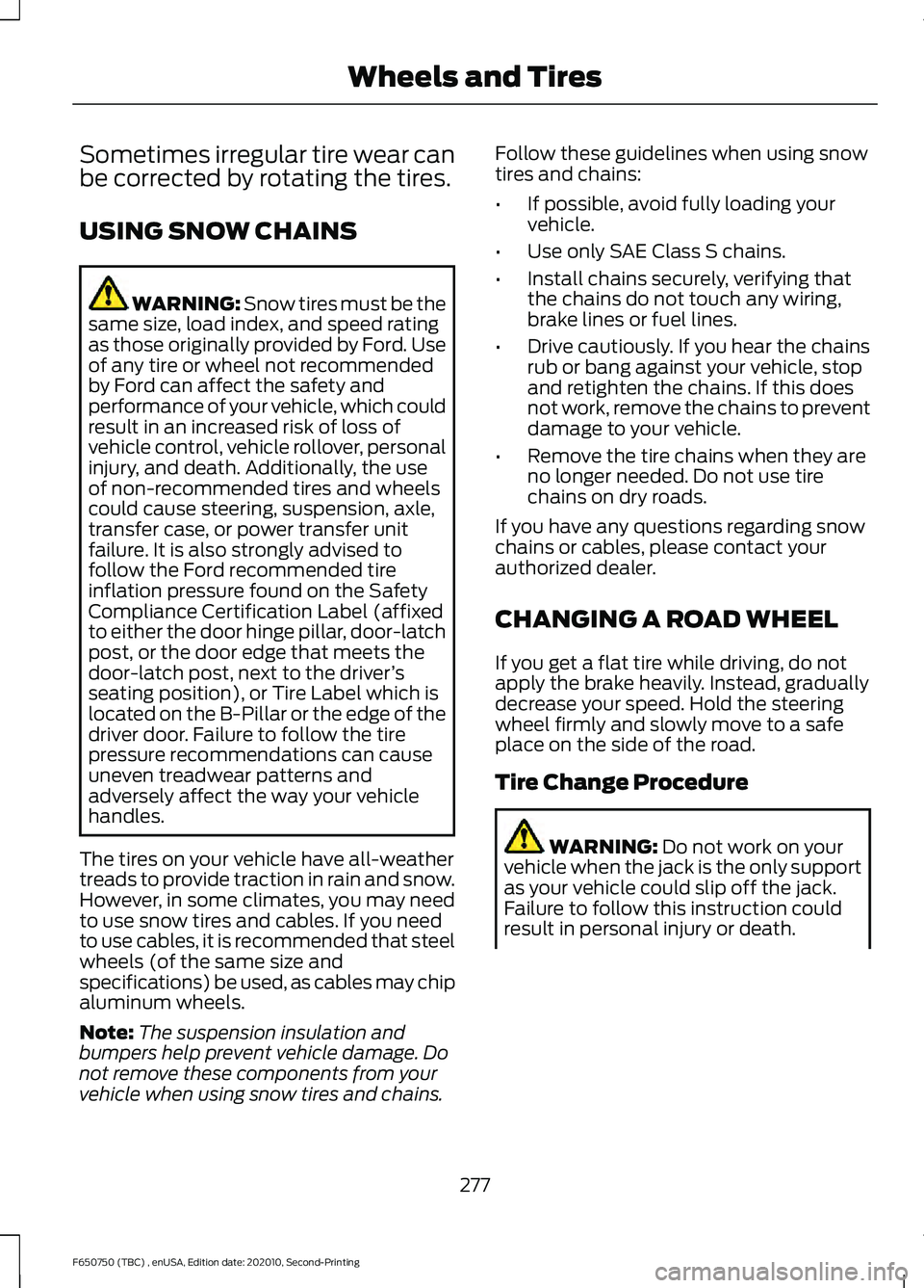
Sometimes irregular tire wear can
be corrected by rotating the tires.
USING SNOW CHAINS
WARNING: Snow tires must be the
same size, load index, and speed rating
as those originally provided by Ford. Use
of any tire or wheel not recommended
by Ford can affect the safety and
performance of your vehicle, which could
result in an increased risk of loss of
vehicle control, vehicle rollover, personal
injury, and death. Additionally, the use
of non-recommended tires and wheels
could cause steering, suspension, axle,
transfer case, or power transfer unit
failure. It is also strongly advised to
follow the Ford recommended tire
inflation pressure found on the Safety
Compliance Certification Label (affixed
to either the door hinge pillar, door-latch
post, or the door edge that meets the
door-latch post, next to the driver ’s
seating position), or Tire Label which is
located on the B-Pillar or the edge of the
driver door. Failure to follow the tire
pressure recommendations can cause
uneven treadwear patterns and
adversely affect the way your vehicle
handles.
The tires on your vehicle have all-weather
treads to provide traction in rain and snow.
However, in some climates, you may need
to use snow tires and cables. If you need
to use cables, it is recommended that steel
wheels (of the same size and
specifications) be used, as cables may chip
aluminum wheels.
Note: The suspension insulation and
bumpers help prevent vehicle damage. Do
not remove these components from your
vehicle when using snow tires and chains. Follow these guidelines when using snow
tires and chains:
•
If possible, avoid fully loading your
vehicle.
• Use only SAE Class S chains.
• Install chains securely, verifying that
the chains do not touch any wiring,
brake lines or fuel lines.
• Drive cautiously. If you hear the chains
rub or bang against your vehicle, stop
and retighten the chains. If this does
not work, remove the chains to prevent
damage to your vehicle.
• Remove the tire chains when they are
no longer needed. Do not use tire
chains on dry roads.
If you have any questions regarding snow
chains or cables, please contact your
authorized dealer.
CHANGING A ROAD WHEEL
If you get a flat tire while driving, do not
apply the brake heavily. Instead, gradually
decrease your speed. Hold the steering
wheel firmly and slowly move to a safe
place on the side of the road.
Tire Change Procedure WARNING:
Do not work on your
vehicle when the jack is the only support
as your vehicle could slip off the jack.
Failure to follow this instruction could
result in personal injury or death.
277
F650750 (TBC) , enUSA, Edition date: 202010, Second-Printing Wheels and Tires
Page 297 of 390
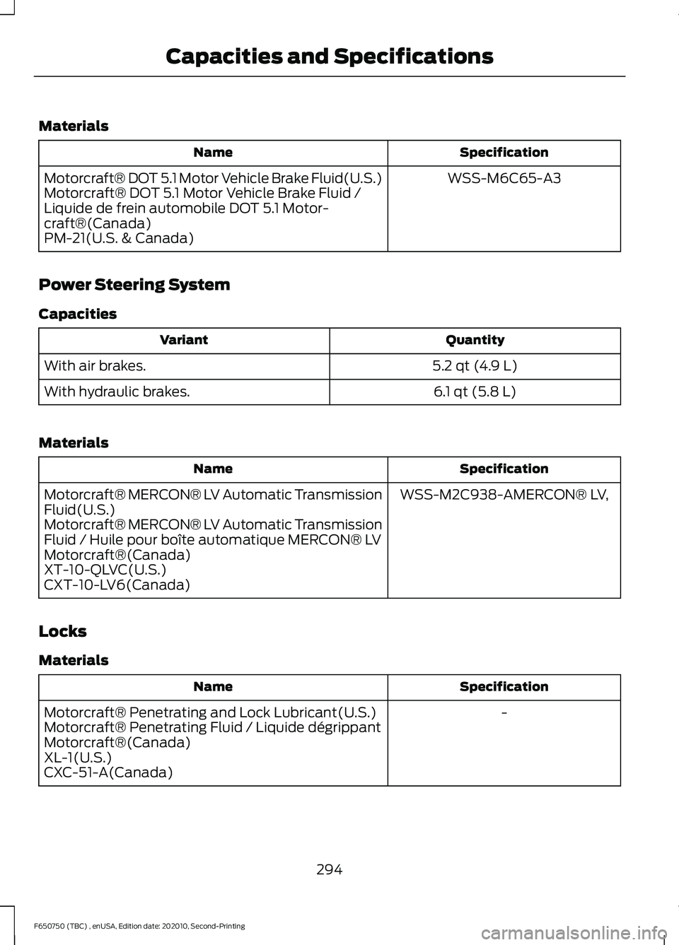
Materials
Specification
Name
WSS-M6C65-A3
Motorcraft® DOT 5.1 Motor Vehicle Brake Fluid(U.S.)
Motorcraft® DOT 5.1 Motor Vehicle Brake Fluid /
Liquide de frein automobile DOT 5.1 Motor-
craft®(Canada)
PM-21(U.S. & Canada)
Power Steering System
Capacities Quantity
Variant
5.2 qt (4.9 L)
With air brakes.
6.1 qt (5.8 L)
With hydraulic brakes.
Materials Specification
Name
WSS-M2C938-AMERCON® LV,
Motorcraft® MERCON® LV Automatic Transmission
Fluid(U.S.)
Motorcraft® MERCON® LV Automatic Transmission
Fluid / Huile pour boîte automatique MERCON® LV
Motorcraft®(Canada)
XT-10-QLVC(U.S.)
CXT-10-LV6(Canada)
Locks
Materials Specification
Name
-
Motorcraft® Penetrating and Lock Lubricant(U.S.)
Motorcraft® Penetrating Fluid / Liquide dégrippant
Motorcraft®(Canada)
XL-1(U.S.)
CXC-51-A(Canada)
294
F650750 (TBC) , enUSA, Edition date: 202010, Second-Printing Capacities and Specifications
Page 305 of 390
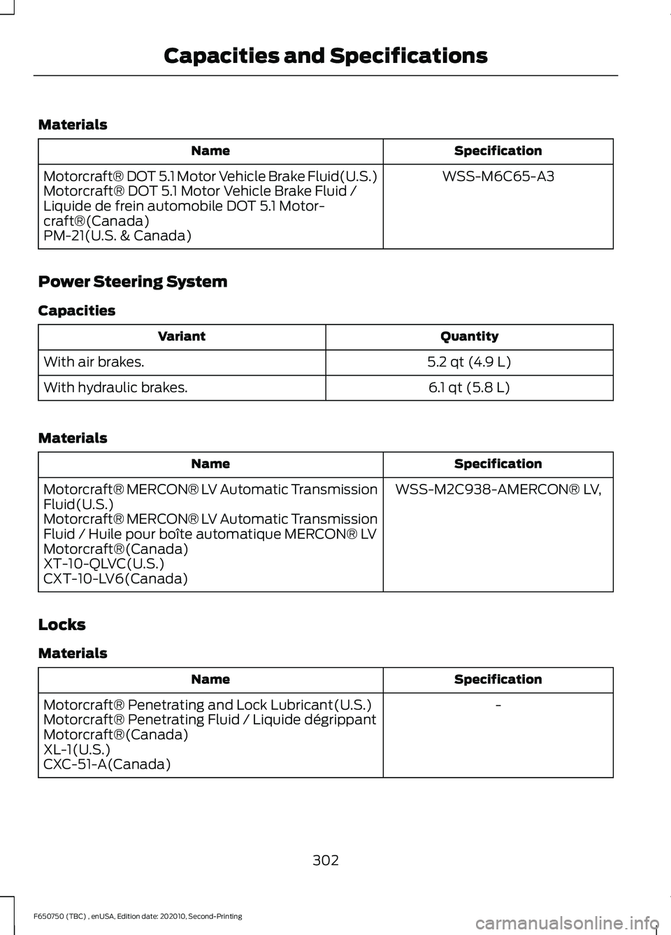
Materials
Specification
Name
WSS-M6C65-A3
Motorcraft® DOT 5.1 Motor Vehicle Brake Fluid(U.S.)
Motorcraft® DOT 5.1 Motor Vehicle Brake Fluid /
Liquide de frein automobile DOT 5.1 Motor-
craft®(Canada)
PM-21(U.S. & Canada)
Power Steering System
Capacities Quantity
Variant
5.2 qt (4.9 L)
With air brakes.
6.1 qt (5.8 L)
With hydraulic brakes.
Materials Specification
Name
WSS-M2C938-AMERCON® LV,
Motorcraft® MERCON® LV Automatic Transmission
Fluid(U.S.)
Motorcraft® MERCON® LV Automatic Transmission
Fluid / Huile pour boîte automatique MERCON® LV
Motorcraft®(Canada)
XT-10-QLVC(U.S.)
CXT-10-LV6(Canada)
Locks
Materials Specification
Name
-
Motorcraft® Penetrating and Lock Lubricant(U.S.)
Motorcraft® Penetrating Fluid / Liquide dégrippant
Motorcraft®(Canada)
XL-1(U.S.)
CXC-51-A(Canada)
302
F650750 (TBC) , enUSA, Edition date: 202010, Second-Printing Capacities and Specifications
Page 318 of 390
AUXILIARY SWITCHES (IF
EQUIPPED)
For maximum vehicle performance, keep
the following information in mind when
adding accessories or equipment to your
vehicle:
• When adding accessories, equipment,
passengers and luggage to your
vehicle, do not exceed the total weight
capacity of the vehicle or of the front
or rear axle (GVWR or GAWR as
indicated on the Safety Compliance
Certification label). Ask an authorized
dealer for specific weight information.
• The Federal Communications
Commission (FCC) and Canadian
Radio Telecommunications
Commission (CRTC) regulate the use
of mobile communications systems
equipped with radio transmitters, for
example, two-way radios, telephones
and theft alarms. Any such equipment
installed in your vehicle should comply
with Federal Communications
Commission (FCC) and Canadian
Radio Telecommunications
Commission (CRTC) regulations, and
should be installed by an authorized
dealer.
• An authorized dealer needs to install
mobile communications systems.
Improper installation may harm the
operation of your vehicle, particularly
if the manufacturer did not design the
mobile communication system
specifically for automotive use.
• If you or an authorized Ford dealer add
any non-Ford electrical or electronic
accessories or components to your
vehicle, you may adversely affect
battery performance and durability. In
addition, you may also adversely affect
the performance of other electrical
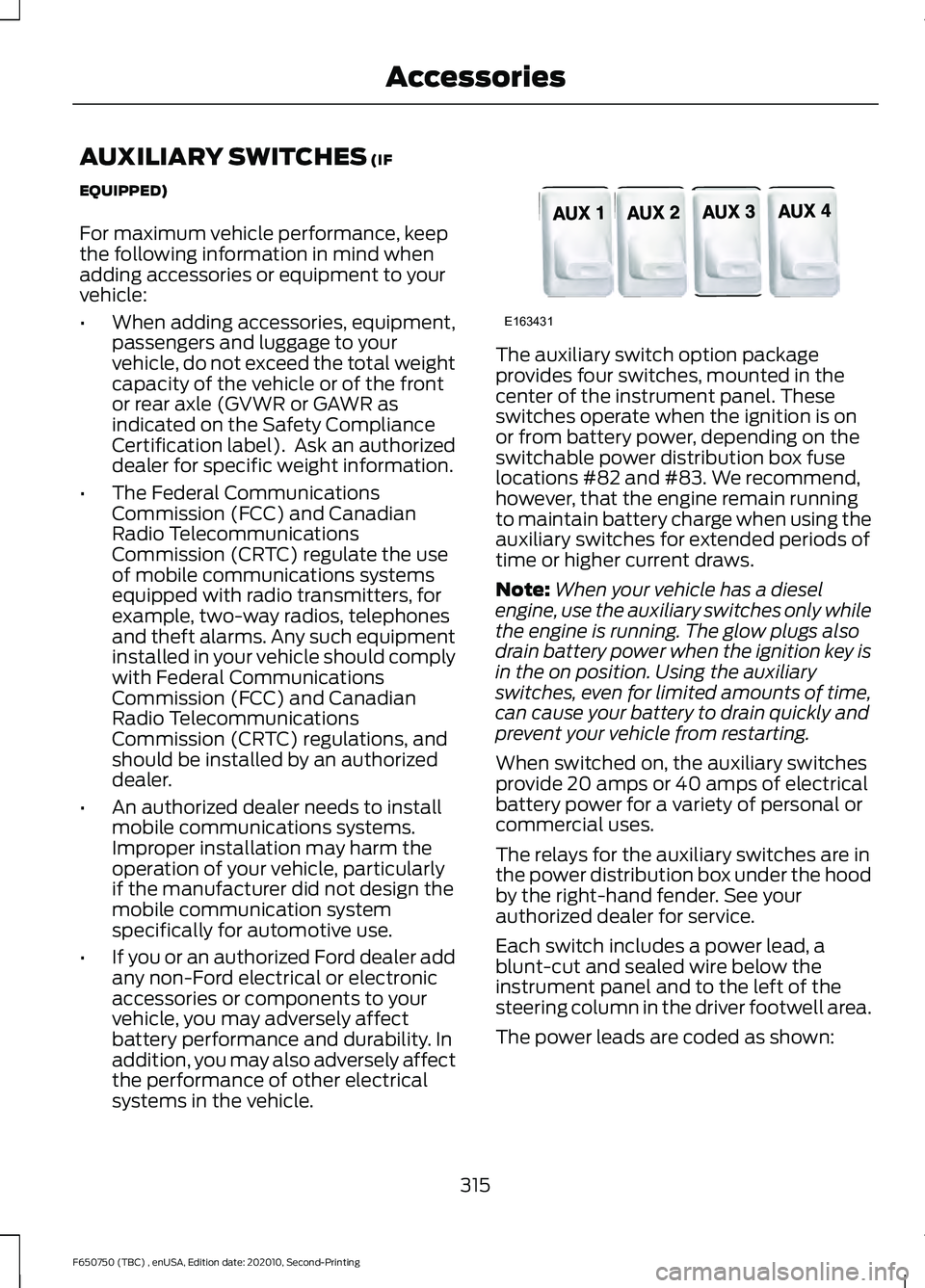
systems in the vehicle. The auxiliary switch option package
provides four switches, mounted in the
center of the instrument panel. These
switches operate when the ignition is on
or from battery power, depending on the
switchable power distribution box fuse
locations #82 and #83. We recommend,
however, that the engine remain running
to maintain battery charge when using the
auxiliary switches for extended periods of
time or higher current draws.
Note:
When your vehicle has a diesel
engine, use the auxiliary switches only while
the engine is running. The glow plugs also
drain battery power when the ignition key is
in the on position. Using the auxiliary
switches, even for limited amounts of time,
can cause your battery to drain quickly and
prevent your vehicle from restarting.
When switched on, the auxiliary switches
provide 20 amps or 40 amps of electrical
battery power for a variety of personal or
commercial uses.
The relays for the auxiliary switches are in
the power distribution box under the hood
by the right-hand fender. See your
authorized dealer for service.
Each switch includes a power lead, a
blunt-cut and sealed wire below the
instrument panel and to the left of the
steering column in the driver footwell area.
The power leads are coded as shown:
315
F650750 (TBC) , enUSA, Edition date: 202010, Second-Printing AccessoriesE163431
Page 326 of 390
Multi-point Inspection
In order to keep your vehicle running right,
it is important to have the systems on your
vehicle checked regularly. This can help
identify potential issues and prevent major
problems. We recommend having the
following multi-point inspection performed
at every scheduled maintenance interval
to help make sure your vehicle keeps
running great.Multi-point Inspection
Horn operation
Accessory drive belt(s)
Radiator, cooler, heater and A/C hoses
Battery performance
Suspension component for leaks ordamage
Engine air filter
Steering and linkage
Exhaust system
Tires (including spare) for wear and properpressure2
Exterior lamps operation
Windshield for cracks, chips or pits
Fluid levels 1
; fill if necessary
Washer spray and wiper operation
For oil and fluid leaks
Hazard warning system operation
Hood rest for lubrication
1 Brake, coolant recovery reservoir, automatic transmission, power steering and window
washer.
2 If your vehicle is equipped with a temporary mobility kit, check the tire sealant expiration
Use By date on the canister. Replace as needed.
Be sure to ask your dealership service
advisor or technician about the multi-point
vehicle inspection. It is a comprehensive
way to perform a thorough inspection of
your vehicle. Your checklist gives you
immediate feedback on the overall
condition of your vehicle. NORMAL SCHEDULED
MAINTENANCE
Intelligent Oil-Life Monitor™ -
Diesel Engine Only
Your diesel engine has an Intelligent
Oil-Life Monitor that determines when you
should change the engine oil based on how
you use your vehicle. By using several
important factors in its calculations, the
monitor helps reduce the cost of owning
your vehicle and reduces environmental
waste at the same time.
323
F650750 (TBC) , enUSA, Edition date: 202010, Second-Printing Scheduled Maintenance