2021 FORD F650/750 key battery
[x] Cancel search: key batteryPage 115 of 390

Your vehicle may not pass the I/M test if
the service engine soon indicator is on or
not working properly (bulb is burned out),
or if the OBD-II system has determined
that some of the emission control systems
have not been properly checked. In this
case, the vehicle is not ready for I/M
testing.
If the vehicle
’s engine or transmission has
just been serviced, or the battery has
recently run down or been replaced, the
OBD-II system may indicate that the
vehicle is not ready for I/M testing. To
determine if the vehicle is ready for I/M
testing, turn the ignition key to the on
position for 15 seconds without cranking
the engine. If the service engine soon
indicator blinks eight times, it means that
the vehicle is not ready for I/M testing; if
the service engine soon indicator stays on
solid, it means that your vehicle is ready
for I/M testing.
The OBD-II system checks the emission
control system during normal driving. A
complete check may take several days.
If the vehicle is not ready for I/M testing,
you can perform the following driving cycle
consisting of mixed city and highway
driving:
1. 15 minutes of steady driving on an expressway or highway followed by 20
minutes of stop-and-go driving with at
least four 30-second idle periods.
2. Allow your vehicle to sit for at least eight hours with the ignition off. Then,
start the vehicle and complete the
above driving cycle. The vehicle must
warm up to its normal operating
temperature. Once started, do not turn
off the vehicle until the above driving
cycle is complete.
If the vehicle is still not ready for I/M
testing, you need to repeat the above
driving cycle. SELECTIVE CATALYTIC
REDUCTANT SYSTEM - DIESEL
Your vehicle may have a selective catalytic
reduction system. The system helps reduce
emission levels of oxides of nitrogen from
the exhaust system. The system
automatically injects diesel exhaust fluid
into the exhaust system to enable correct
selective catalytic reduction system
function.
Note:
Selective catalytic reduction systems
are not fitted to vehicles in markets where
only high-sulfur diesel fuel is available.
Diesel Exhaust Fluid Level
In order for the system to operate correctly
you must maintain the diesel exhaust fluid
level.
The system has a sensor to monitor fluid
level and quality/concentration. A warning
message appears in the information
display when the diesel exhaust fluid level
is low. If a warning message appears, refill
the diesel exhaust fluid tank as soon as
possible. See Information Messages
(page 73).
Filling the Diesel Exhaust Fluid
Tank WARNING:
Keep diesel exhaust
fluid out of reach of children. Avoid
contact with skin, eyes or clothing. In
case of contact with your eyes, flush
immediately with water and get prompt
medical attention. In case of contact
with your skin, clean immediately with
soap and water. If you swallow any
diesel exhaust fluid, drink plenty of
water, call a physician immediately.
112
F650750 (TBC) , enUSA, Edition date: 202010, Second-Printing Engine Emission Control
Page 184 of 390

ROADSIDE ASSISTANCE
Vehicles Sold in the United States:
Getting Roadside Assistance
To fully assist you should you have a
vehicle concern, Ford Motor Company
offers a complimentary roadside
assistance program. This program is
separate from the New Vehicle Limited
Warranty.
The service is available:
•
24 hours a day, seven days a week.
• For the coverage period supplied with
your vehicle.
Roadside Assistance covers:
• A flat tire change with a good spare
(except vehicles supplied with a tire
inflation kit).
• Battery jump start.
• Lock-out assistance (key replacement
cost is the customer's responsibility).
• Fuel delivery — independent service
contractors, if not prohibited by state,
local or municipal law, shall deliver up
to 2 gal (8 L) of gasoline or 5 gal (20 L)
of diesel fuel to a disabled vehicle.
Roadside Assistance limits fuel delivery
service to two no-charge occurrences
within a 12-month period.
• Winch out — available within 100 ft
(30 m) of a paved or county
maintained road, no recoveries. •
Towing — independent service
contractors, if not prohibited by state,
local or municipal law, shall tow Ford
eligible vehicles to an authorized dealer
within
35 mi (56 km) of the
disablement location or to the nearest
authorized dealer. If a member
requests a tow to an authorized dealer
that is more than
35 mi (56 km) from
the disablement location, the member
shall be responsible for any mileage
costs in excess of
35 mi (56 km).
• Roadside Assistance includes up to
$200 for a towed trailer if the disabled
eligible vehicle requires service at the
nearest authorized dealer. If the towing
vehicle is operational but the trailer is
not, then the trailer does not qualify for
any roadside services.
Vehicles Sold in the United States:
Using Roadside Assistance
Complete the roadside assistance
identification card and place it in your
wallet for quick reference. This card is in
the Owner's Manual kit.
United States vehicle customers who
require Roadside Assistance, call
1-800-241-3673.
If you need to arrange roadside assistance
for yourself, Ford Motor Company
reimburses a reasonable amount for
towing to the nearest dealership within
35 mi (56 km)
. To obtain reimbursement
information, United States vehicle
customers call 1-800-241-3673.
Customers need to submit their original
receipts.
181
F650750 (TBC) , enUSA, Edition date: 202010, Second-Printing Roadside Emergencies
Page 185 of 390

Vehicles Sold in Canada: Getting
Roadside Assistance
To fully assist you should you have a
vehicle concern, Ford Motor Company of
Canada, Limited offers a complimentary
roadside assistance program. This program
is eligible within Canada or the continental
United States.
The service is available 24 hours a day,
seven days a week.
This program is separate from the New
Vehicle Limited Warranty, but the coverage
is concurrent with the powertrain coverage
period of your vehicle. Canadian roadside
coverage and benefits may differ from the
U.S. coverage.
If you require more information, please call
us in Canada at 1-800-665-2006, or visit
our website at www.ford.ca.
HAZARD FLASHERS
Note:
If used when the vehicle is not
running, the battery loses charge. As a result,
there may be insufficient power to restart
your vehicle. The hazard flasher control is located on
the instrument panel. Use it when your
vehicle is creating a safety hazard for other
motorists. •
Press the flasher control and all front
and rear direction indicators flash.
• Press the flasher control again to
switch them off.
FUEL SHUTOFF WARNING: If your vehicle has been
involved in a crash, have the fuel system
checked. Failure to follow this instruction
could result in fire, personal injury or
death.
Note: When you try to restart your vehicle
after a fuel shutoff, your vehicle makes sure
that various systems are safe to restart.
Once your vehicle determines that the
systems are safe, your vehicle allows you to
restart.
Note: In the event that your vehicle does
not restart after your third attempt, contact
a qualified technician.
The fuel pump shutoff stops the flow of
fuel to the engine in the event of a
moderate to severe crash. Not every
impact causes a shutoff.
Should your vehicle shut off after a crash,
you may restart your vehicle.
If your vehicle has a key system:
1. Turn key to the off position.
2. Turn key to the start position.
3. Turn key to the off position.
4. Turn key to the on position.
5. The fuel pump is now re-enabled.
182
F650750 (TBC) , enUSA, Edition date: 202010, Second-Printing Roadside EmergenciesE304635
Page 243 of 390

5. Turn the air conditioning (if equipped)
on and allow the engine to idle for at
least one minute.
6. Release the parking brake. With your foot on the brake pedal and with the
air conditioning on, put the vehicle in
drive (D) and allow the engine to idle
for at least one minute.
•If you do not allow the engine to
relearn its idle trim, the idle quality
of your vehicle may be adversely
affected until the idle trim is
eventually relearned.
7. Drive the vehicle to complete the relearning process
•The vehicle may need to be driven
10 mi (16 km) or more to relearn the
idle and fuel trim strategy along
with the ethanol content for flexible
fuel vehicles.
If the battery has been disconnected or a
new battery has been installed, the clock
and radio settings must be reset once the
battery is reconnected.
Always dispose of automotive
batteries in a responsible manner.
Follow your local authorized standards
for disposal. Call your local authorized
recycling center to find out more about
recycling automotive batteries.
Battery Management System (If
Equipped)
The battery management system (BMS)
monitors battery conditions and takes
actions to extend battery life. If excessive
battery drain is detected, the system may
temporarily disable certain electrical
features to protect the battery. Those
electrical accessories affected include the
rear defrost, heated/cooled seats, climate
control fan, heated steering wheel, audio
and navigation system. A message may be
shown in the information displays to alert the driver that battery protection actions
are active. These messages are only for
notification that an action is taking place,
and not intended to indicate an electrical
problem or that the battery requires
replacement.
Electrical accessory installation
To ensure proper operation of the BMS,
any electrical devices that are added to
the vehicle should not have their ground
connection made directly at the negative
battery post. A connection at the negative
battery post can cause inaccurate
measurements of the battery condition
and potential incorrect system operation.
Note:
Electrical or electronic accessories
added to the vehicle by the dealer or the
owner may adversely affect battery
performance and durability, and may also
affect the performance of other electrical
systems in the vehicle.
When a battery replacement is required,
the battery should only be replaced with
a Ford recommended replacement battery
which matches the electrical requirements
of the vehicle. After battery replacement,
or in some cases after charging the battery
with the external charger, the BMS requires
eight hours of vehicle sleep time (key off
with doors closed) to relearn the new
battery state of charge. Prior to relearning
the state of charge, the BMS may disable
electrical features (to protect the battery)
earlier than normal.
ADJUSTING THE HEADLAMPS
Vertical Aim Adjustment
The headlamps on your vehicle are
properly aimed at the assembly plant. If
your vehicle has been in an accident, the
alignment of your headlamps should be
checked by your authorized dealer.
240
F650750 (TBC) , enUSA, Edition date: 202010, Second-Printing Maintenance
Page 318 of 390

AUXILIARY SWITCHES (IF
EQUIPPED)
For maximum vehicle performance, keep
the following information in mind when
adding accessories or equipment to your
vehicle:
• When adding accessories, equipment,
passengers and luggage to your
vehicle, do not exceed the total weight
capacity of the vehicle or of the front
or rear axle (GVWR or GAWR as
indicated on the Safety Compliance
Certification label). Ask an authorized
dealer for specific weight information.
• The Federal Communications
Commission (FCC) and Canadian
Radio Telecommunications
Commission (CRTC) regulate the use
of mobile communications systems
equipped with radio transmitters, for
example, two-way radios, telephones
and theft alarms. Any such equipment
installed in your vehicle should comply
with Federal Communications
Commission (FCC) and Canadian
Radio Telecommunications
Commission (CRTC) regulations, and
should be installed by an authorized
dealer.
• An authorized dealer needs to install
mobile communications systems.
Improper installation may harm the
operation of your vehicle, particularly
if the manufacturer did not design the
mobile communication system
specifically for automotive use.
• If you or an authorized Ford dealer add
any non-Ford electrical or electronic
accessories or components to your
vehicle, you may adversely affect
battery performance and durability. In
addition, you may also adversely affect
the performance of other electrical
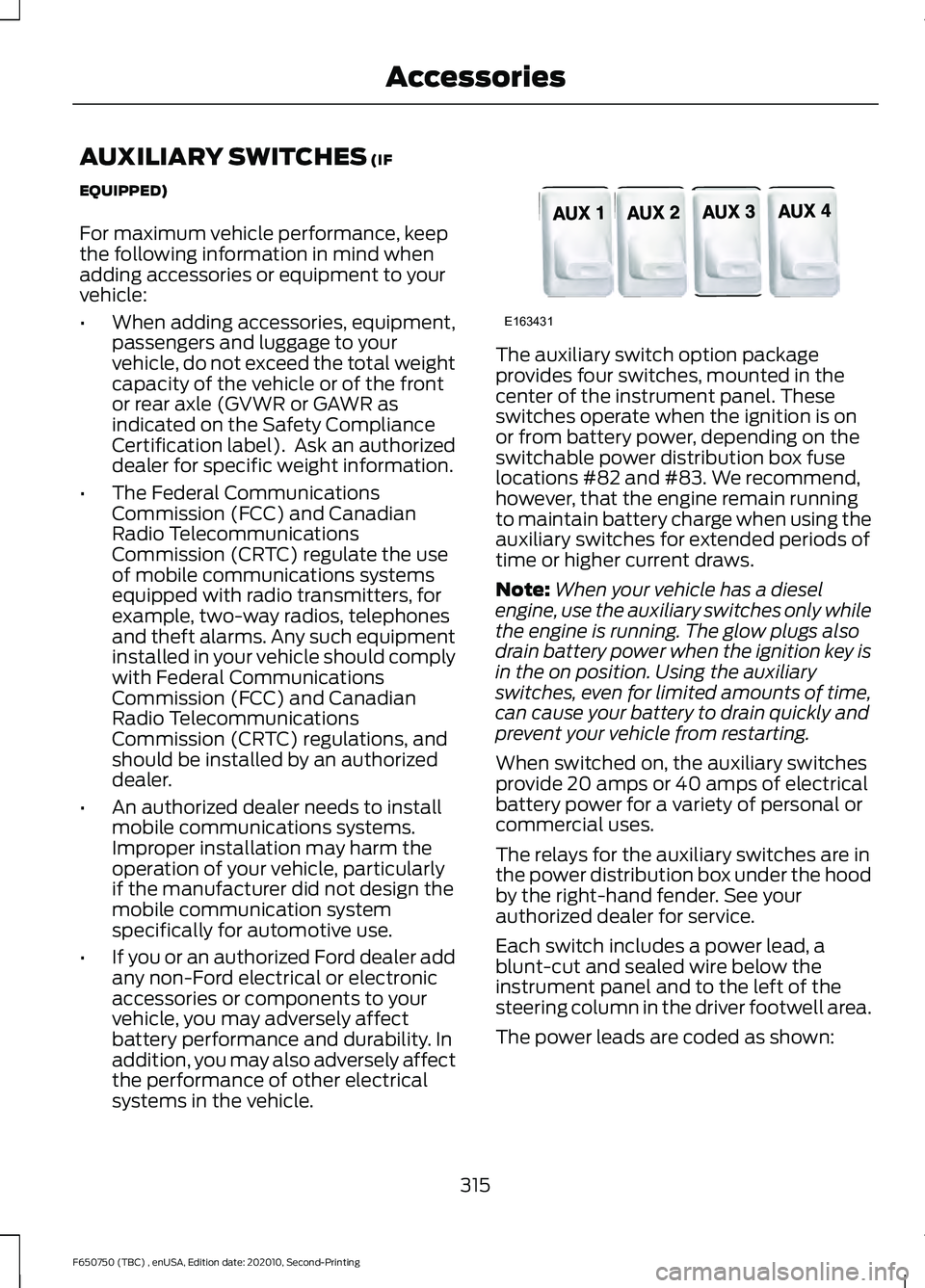
systems in the vehicle. The auxiliary switch option package
provides four switches, mounted in the
center of the instrument panel. These
switches operate when the ignition is on
or from battery power, depending on the
switchable power distribution box fuse
locations #82 and #83. We recommend,
however, that the engine remain running
to maintain battery charge when using the
auxiliary switches for extended periods of
time or higher current draws.
Note:
When your vehicle has a diesel
engine, use the auxiliary switches only while
the engine is running. The glow plugs also
drain battery power when the ignition key is
in the on position. Using the auxiliary
switches, even for limited amounts of time,
can cause your battery to drain quickly and
prevent your vehicle from restarting.
When switched on, the auxiliary switches
provide 20 amps or 40 amps of electrical
battery power for a variety of personal or
commercial uses.
The relays for the auxiliary switches are in
the power distribution box under the hood
by the right-hand fender. See your
authorized dealer for service.
Each switch includes a power lead, a
blunt-cut and sealed wire below the
instrument panel and to the left of the
steering column in the driver footwell area.
The power leads are coded as shown:
315
F650750 (TBC) , enUSA, Edition date: 202010, Second-Printing AccessoriesE163431
Page 385 of 390

Head Restraints..............................................82
Adjusting the Head Restraint.......................... 83
Heated Exterior Mirrors.................................81
Heating See: Climate Control........................................... 79
Hill Start Assist..............................................134 Switching the System On and Off...............134
Using Hill Start Assist....................................... 134
Hints on Controlling the Interior Climate...........................................................80
Defogging the Side Windows in Cold Weather............................................................... 81
General Hints........................................................ 80
Quickly Cooling the Interior............................. 80
Quickly Heating the Interior............................. 80
Recommended Settings for Cooling............80
Recommended Settings for Heating...........80
Vehicle Stationary for Extended Periods During Extreme High Ambient
Temperatures.................................................... 81
Hints on Driving With Anti-Lock Brakes..............................................................131
Hood Lock See: Opening and Closing the Hood...........213
Horn
.....................................................................53
I
Ignition Switch
................................................93
In California (U.S. Only).............................188
Information Display Control.......................53
Information Displays
.....................................70
General Information............................................ 70
Information Messages
..................................73
Diesel Messages.................................................... 74
Engine........................................................................\
77
Fuel........................................................................\
..... 77
Key........................................................................\
...... 77
Maintenance........................................................... 77
Park Brake............................................................... 78
Installing Child Restraints...........................26 Child Restraints..................................................... 26
Tether Strap Attachment................................... 31
Using Cinch Tongue Lap and Shoulder Belts (All Front Center, Super Cab and Crew
Cab Rear Center Positions)......................... 28
Using Lap and Shoulder Belts......................... 26Using Lower Anchors and Tethers for
CHildren (LATCH)........................................... 30
Using Tether Straps............................................ 30
Instrument Cluster
.........................................63
Instrument Lighting Dimmer.....................56
Instrument Panel............................................22
Interior Lamps
.................................................58
Interior Mirror...................................................62
Introduction.........................................................7
J
Jump Starting the Vehicle.........................183 Connecting the Jumper Cables..................... 183
Jump Starting...................................................... 184
Preparing Your Vehicle..................................... 183
Removing the Jumper Cables........................ 184
K
Keys and Remote Controls.........................45
L
Lane Keeping System..................................157 Switching the System On and Off...............158
System Display.................................................... 158
System Settings.................................................. 158
Troubleshooting.................................................. 159
Lighting Control
..............................................55
Flashing the Headlamp High Beam..............56
Headlamp High Beam........................................ 55
Lighting..............................................................55 General Information............................................ 55
Load Carrying.................................................168
Load Limit.......................................................168 Unloaded or Lightly Loaded Vehicles.........168
Locating the USB Ports
................................91
Charge Only USB Ports....................................... 91
Data Transfer USB Ports.................................... 91
Locking and Unlocking.................................49 Autolock.................................................................. 49
Battery Saver......................................................... 50
Illuminated Entry.................................................. 50
Power Door Locks................................................ 49
Remote Control.................................................... 49
Smart Unlocks...................................................... 49
382
F650750 (TBC) , enUSA, Edition date: 202010, Second-Printing Index
Page 387 of 390

Blocked Sensors.................................................
166
Distance Indication and Alert........................ 165
Using the Pre-Collision Assist System............................................................... 164
Protecting the Environment........................21
Puncture See: Changing a Road Wheel........................ 277
R
Rear Axle Fluid Check.................................253 Changing the Fluid............................................ 253
Checking the Fluid Level................................. 253
Rear Axle..........................................................128 General Information.......................................... 128
Rear Seat Armrest.........................................88
Rear Seats
........................................................86
Folding the Rear Seat Back (Crew Cab)
........................................................................\
........ 87
Folding up the Rear Seat Cushion.................. 87
Returning the Seat to the Seating Position............................................................... 87
Recommended Towing Weights.............172
Refueling - Diesel
.........................................104
Fuel Filler Cap...................................................... 105
Fuel Fill Rate......................................................... 105
Refueling - Gasoline
....................................105
Fuel Filler Cap...................................................... 106
Remote Control
..............................................46
Car Finder................................................................ 47
Changing the Remote Control Battery........46
Reprogramming the Remote Control..........46
Sounding the Panic Alarm................................ 47
Removing a Headlamp..............................243
Repairing Minor Paint Damage..............259
Replacement Parts Recommendation .........................................
17
Collision Repairs..................................................... 17
Scheduled Maintenance and Mechanical Repairs.................................................................. 17
Warranty on Replacement Parts..................... 17
Replacing a Lost Key or Remote Control............................................................48
Reporting Safety Defects (Canada Only)...............................................................192
Reporting Safety Defects (U.S. Only)................................................................191
Resuming the Set Speed
...........................155 Roadside Assistance
....................................181
Vehicles Sold in Canada: Getting Roadside
Assistance........................................................ 182
Vehicles Sold in the United States: Getting Roadside Assistance..................................... 181
Vehicles Sold in the United States: Using Roadside Assistance..................................... 181
Roadside Emergencies................................181
Running-In See: Breaking-In.................................................. 179
Running Out of Fuel - Diesel....................103 Purging Air From the System......................... 104
Starting the Engine............................................ 104
Running Out of Fuel - Gasoline..............104
S
Safety Precautions
........................................99
Low Fuel Pressure.............................................. 100
Scheduled Maintenance Record
............337
Scheduled Maintenance............................319
Seatbelt Extensions......................................44
Seatbelt Height Adjustment.......................41
Seatbelt Reminder.........................................42 Belt-Minder™........................................................ 42
Seatbelts............................................................37 Principle of Operation......................................... 37
Seatbelt Warning Lamp and Indicator Chime...............................................................42
Conditions of operation..................................... 42
Seats...................................................................82
Security...............................................................51
Selective Catalytic Reductant System - Diesel...............................................................112
Contaminated Diesel Exhaust Fluid or Inoperative Selective Catalytic Reduction
System................................................................ 116
Diesel Exhaust Fluid Guidelines and Information....................................................... 115
Diesel Exhaust Fluid Level................................ 112
Diesel Exhaust Fluid Warning Messages and Vehicle Operations................................ 114
Filling the Diesel Exhaust Fluid Tank............112
Setting the Cruise Control Speed..........154 Changing the Set Speed.................................. 154
Sitting in the Correct Position...................82
Snow Chains See: Using Snow Chains.................................. 277
384
F650750 (TBC) , enUSA, Edition date: 202010, Second-Printing Index