2021 FORD F650/750 light
[x] Cancel search: lightPage 208 of 390

Engine starting (with parking brake applied)
Check the gauge (diesel engine) or indicator light (gasoline
engine) to verify the alternator is charging.
Voltmeter
Inspect for excessive free play in the steering linkages. The
steering wheel should have less than 2 in (5 cm) of free play
at its rim.
Steering linkage free play
Verify the parking brake holds the vehicle by gently trying to
pull forward with the parking brake applied.
Parking brake
Verify operation using the following procedure. Chock the
wheels, if necessary. Push in the parking brake and, on
tractors, push in the tractor parking brake knob:
Air brakes
1. Verify the air compressor or governor cutout pressure is
approximately 120 psi (827 kPa).
2. Turn off the engine, and then turn the key back to the on
position (without starting the engine).
3. Without the brake pedal applied, note the air pressure drop
for one minute. It should be less than 2 psi (14 kPa) for single
vehicles and
3 psi (21 kPa) for combination vehicles.
4. Press and hold the brake pedal with
90 psi (621 kPa) or
more. Make sure there is no more than a 3 psi (21 kPa) per
minute leak for single vehicles and a 4 psi (28 kPa) minute
leak for combination vehicles.
5. Pump the brake pedal to deplete the system of air pressure.
The warning light and tone should turn on at 57 psi (393 kPa).
6. Pump the brake pedal and make sure the parking brake
and trailer parking brake knobs pop out at
20 psi (138 kPa)
or higher.
Verify that the fluid level is in the proper operating range. See
Automatic Transmission Fluid Check
(page 236).
Automatic transmission
fluid Front of vehicle
Verify all exterior lights illuminate and are clean.
Lights
Check headlights function on high and low beam.
Verify reflectors are clean, unbroken and of proper color (red
on rear, amber elsewhere).
205
F650750 (TBC) , enUSA, Edition date: 202010, Second-Printing Vehicle Inspection Guide
Page 209 of 390

Front of vehicle
Verify running lights are clean and unbroken.
Inspect for any missing or loose fasteners, power steering
fluid leaks and damage to power steering hoses.
Steering gear
Verify connecting links, arms and rods are not worn or cracked.
Steering linkage
Verify joints, sockets and boot seals are not worn or loose.
Verify cotter keys, nuts and bolts are not loose or missing.
Inspect front and rear tow hooks for damage or loose
mounting. This is particularly important on vehicles that use
them frequently.
Tow hooks Front suspension
Inspect for missing, broken or shifted leaves, or leaves that
may be in contact with (or nearly contacting) a tire, rim, brake
drum, frame or body component.
Springs
Note: Never apply grease to spring pads.
Make sure there the following items are properly tightened
and that there are no cracks, breaks, wear, damage to spring
hangers, bolts, bushings, axle mounting bolts, and nuts.
Spring mounts
Inspect for any cracks, leaks, or missing or broken bolts or
bushings.
Shock absorbers
206
F650750 (TBC) , enUSA, Edition date: 202010, Second-Printing Vehicle Inspection Guide
Page 211 of 390
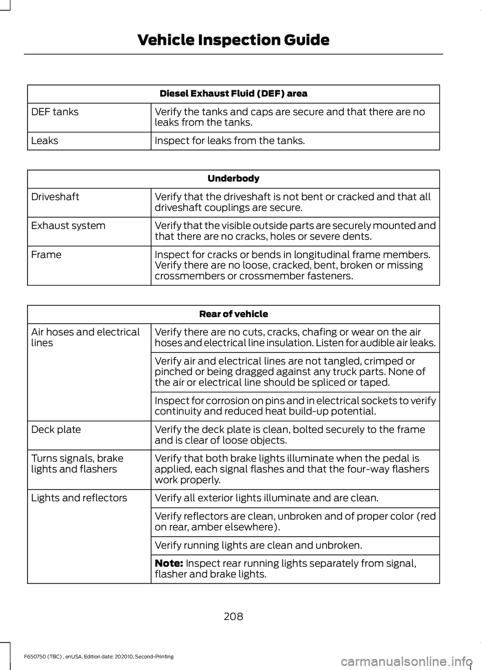
Diesel Exhaust Fluid (DEF) area
Verify the tanks and caps are secure and that there are no
leaks from the tanks.
DEF tanks
Inspect for leaks from the tanks.
Leaks Underbody
Verify that the driveshaft is not bent or cracked and that all
driveshaft couplings are secure.
Driveshaft
Verify that the visible outside parts are securely mounted and
that there are no cracks, holes or severe dents.
Exhaust system
Inspect for cracks or bends in longitudinal frame members.
Verify there are no loose, cracked, bent, broken or missing
crossmembers or crossmember fasteners.
Frame Rear of vehicle
Verify there are no cuts, cracks, chafing or wear on the air
hoses and electrical line insulation. Listen for audible air leaks.
Air hoses and electrical
lines
Verify air and electrical lines are not tangled, crimped or
pinched or being dragged against any truck parts. None of
the air or electrical line should be spliced or taped.
Inspect for corrosion on pins and in electrical sockets to verify
continuity and reduced heat build-up potential.
Verify the deck plate is clean, bolted securely to the frame
and is clear of loose objects.
Deck plate
Verify that both brake lights illuminate when the pedal is
applied, each signal flashes and that the four-way flashers
work properly.
Turns signals, brake
lights and flashers
Verify all exterior lights illuminate and are clean.
Lights and reflectors
Verify reflectors are clean, unbroken and of proper color (red
on rear, amber elsewhere).
Verify running lights are clean and unbroken.
Note: Inspect rear running lights separately from signal,
flasher and brake lights.
208
F650750 (TBC) , enUSA, Edition date: 202010, Second-Printing Vehicle Inspection Guide
Page 213 of 390

Rear brakes
Inspect for cracked, worn or frayed hoses, and that all coup-
lings are secure.
Hoses
Verify that there are no cracks or dents, and that the cham-
bers are securely mounted.
Brake chambers
Inspect for broken, loose or missing parts.
Slack adjusters
Note: The angle between the push rod and adjuster arm
should be approximately 90 degrees when the brakes are
applied. When pulled by hand, the push rod should not move
more than approximately
1 in (2.5 cm).
Verify that there are no cracks, dents, holes, and no loose or
missing bolts and that the brake linings are not worn,
dangerously thin or contaminated by lubricant.
Drums Rear wheels
Check for even separation of dual wheels, and that the tires
are not touching each other.
Spacers
Inspect for damaged or bent rims. They should not have
welding repairs, and there should be no rust trails, which
indicate it is loose on the wheel.
Rims
Verify all lug nuts are present and not loose (look for rust
trails around the lug nuts). There should be no cracks radiating
from the lug bolt holes or distortion of the bolt holes.
Lug nuts
Trailer
If you are pulling a trailer, perform an
inspection of the trailer similar to that of
the tractor. The inspection should follow
trailer manufacturer recommendations
and should include at a minimum: general
condition, landing gear, doors, sides, lights,
reflectors, suspension, brakes, tires,
wheels, cargo placement, stability and
tie-downs. Transmission WARNING:
If the unit starts in gear
and/or the neutral start switch is not
functioning correctly, the vehicle may
inadvertently move which could result
in property damage, personal injury or
death.
Regularly inspect the transmission's
neutral start switch. The engine should
only start in neutral (N) or park (P) (if
equipped with a park position).
210
F650750 (TBC) , enUSA, Edition date: 202010, Second-Printing Vehicle Inspection Guide
Page 226 of 390
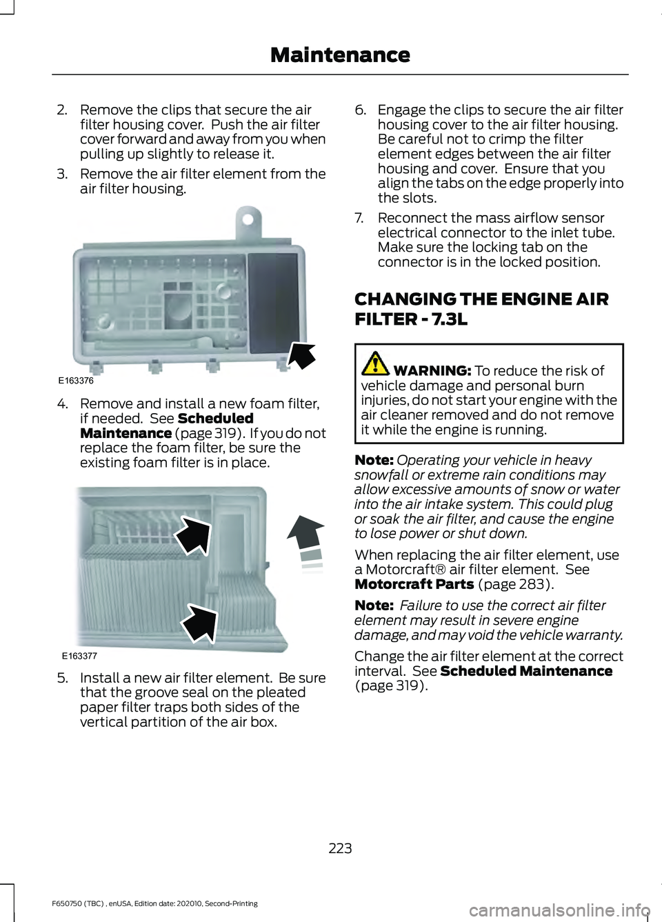
2. Remove the clips that secure the air
filter housing cover. Push the air filter
cover forward and away from you when
pulling up slightly to release it.
3. Remove the air filter element from the
air filter housing. 4. Remove and install a new foam filter,
if needed. See Scheduled
Maintenance (page 319). If you do not
replace the foam filter, be sure the
existing foam filter is in place. 5.
Install a new air filter element. Be sure
that the groove seal on the pleated
paper filter traps both sides of the
vertical partition of the air box. 6. Engage the clips to secure the air filter
housing cover to the air filter housing.
Be careful not to crimp the filter
element edges between the air filter
housing and cover. Ensure that you
align the tabs on the edge properly into
the slots.
7. Reconnect the mass airflow sensor electrical connector to the inlet tube.
Make sure the locking tab on the
connector is in the locked position.
CHANGING THE ENGINE AIR
FILTER - 7.3L WARNING:
To reduce the risk of
vehicle damage and personal burn
injuries, do not start your engine with the
air cleaner removed and do not remove
it while the engine is running.
Note: Operating your vehicle in heavy
snowfall or extreme rain conditions may
allow excessive amounts of snow or water
into the air intake system. This could plug
or soak the air filter, and cause the engine
to lose power or shut down.
When replacing the air filter element, use
a Motorcraft® air filter element. See
Motorcraft Parts
(page 283).
Note: Failure to use the correct air filter
element may result in severe engine
damage, and may void the vehicle warranty.
Change the air filter element at the correct
interval. See
Scheduled Maintenance
(page 319).
223
F650750 (TBC) , enUSA, Edition date: 202010, Second-Printing MaintenanceE163376 E163377
Page 228 of 390
5. Remove the clips that secure the air
filter housing cover. Push the air filter
cover toward the center of the vehicle
and up slightly to release it.
6. Remove the air filter element from the
air filter housing.
7. Install the new air filter element.
8. Engage the clips to secure the air filter housing cover to the air filter housing.
Be careful not to crimp the filter
element edges between the air filter
housing and cover. Ensure that you
align the tabs on the edge properly into
the slots.
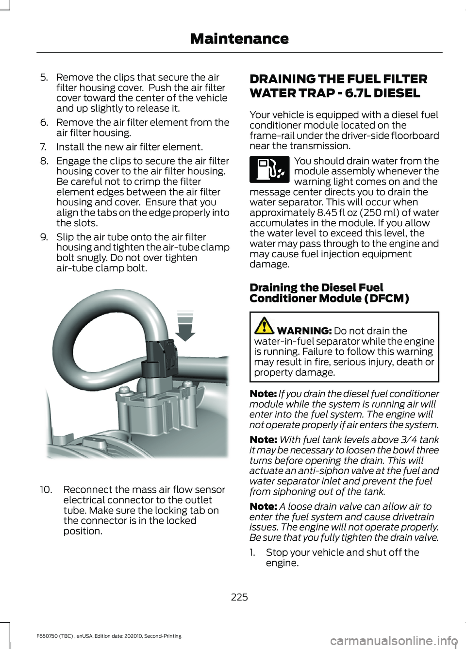
9. Slip the air tube onto the air filter housing and tighten the air-tube clamp
bolt snugly. Do not over tighten
air-tube clamp bolt. 10. Reconnect the mass air flow sensor
electrical connector to the outlet
tube. Make sure the locking tab on
the connector is in the locked
position. DRAINING THE FUEL FILTER
WATER TRAP - 6.7L DIESEL
Your vehicle is equipped with a diesel fuel
conditioner module located on the
frame-rail under the driver-side floorboard
near the transmission. You should drain water from the
module assembly whenever the
warning light comes on and the
message center directs you to drain the
water separator. This will occur when
approximately 8.45 fl oz (250 ml) of water
accumulates in the module. If you allow
the water level to exceed this level, the
water may pass through to the engine and
may cause fuel injection equipment
damage.
Draining the Diesel Fuel
Conditioner Module (DFCM) WARNING: Do not drain the
water-in-fuel separator while the engine
is running. Failure to follow this warning
may result in fire, serious injury, death or
property damage.
Note: If you drain the diesel fuel conditioner
module while the system is running air will
enter into the fuel system. The engine will
not operate properly if air enters the system.
Note: With fuel tank levels above 3⁄4 tank
it may be necessary to loosen the bowl three
turns before opening the drain. This will
actuate an anti-siphon valve at the fuel and
water separator inlet and prevent the fuel
from siphoning out of the tank.
Note: A loose drain valve can allow air to
enter the fuel system and cause drivetrain
issues. The engine will not operate properly.
Be sure that you fully tighten the drain valve.
1. Stop your vehicle and shut off the engine.
225
F650750 (TBC) , enUSA, Edition date: 202010, Second-Printing MaintenanceE317619
Page 229 of 390
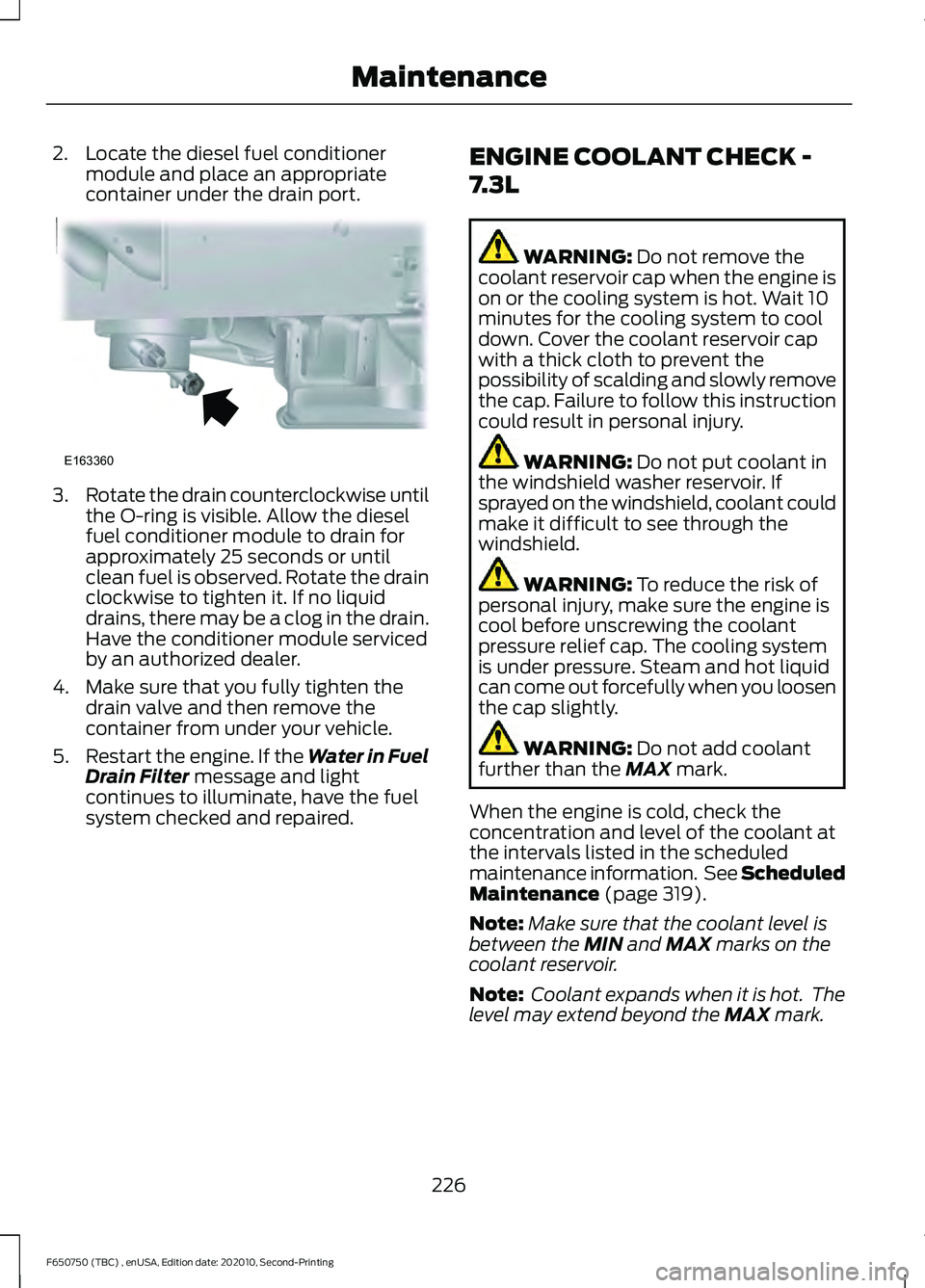
2. Locate the diesel fuel conditioner
module and place an appropriate
container under the drain port. 3.
Rotate the drain counterclockwise until
the O-ring is visible. Allow the diesel
fuel conditioner module to drain for
approximately 25 seconds or until
clean fuel is observed. Rotate the drain
clockwise to tighten it. If no liquid
drains, there may be a clog in the drain.
Have the conditioner module serviced
by an authorized dealer.
4. Make sure that you fully tighten the drain valve and then remove the
container from under your vehicle.
5. Restart the engine. If the Water in Fuel
Drain Filter message and light
continues to illuminate, have the fuel
system checked and repaired. ENGINE COOLANT CHECK -
7.3L WARNING:
Do not remove the
coolant reservoir cap when the engine is
on or the cooling system is hot. Wait 10
minutes for the cooling system to cool
down. Cover the coolant reservoir cap
with a thick cloth to prevent the
possibility of scalding and slowly remove
the cap. Failure to follow this instruction
could result in personal injury. WARNING:
Do not put coolant in
the windshield washer reservoir. If
sprayed on the windshield, coolant could
make it difficult to see through the
windshield. WARNING:
To reduce the risk of
personal injury, make sure the engine is
cool before unscrewing the coolant
pressure relief cap. The cooling system
is under pressure. Steam and hot liquid
can come out forcefully when you loosen
the cap slightly. WARNING:
Do not add coolant
further than the MAX mark.
When the engine is cold, check the
concentration and level of the coolant at
the intervals listed in the scheduled
maintenance information. See Scheduled
Maintenance
(page 319).
Note: Make sure that the coolant level is
between the
MIN and MAX marks on the
coolant reservoir.
Note: Coolant expands when it is hot. The
level may extend beyond the
MAX mark.
226
F650750 (TBC) , enUSA, Edition date: 202010, Second-Printing MaintenanceE163360
Page 231 of 390
4.
Replace the coolant reservoir cap. Turn
the cap clockwise until it contacts the
hard stop.
5. Check the coolant level in the coolant reservoir the next few times you drive
your vehicle. If necessary, add enough
prediluted engine coolant to bring the
coolant level to the proper level.
Note: If prediluted coolant is not available,
use the approved antifreeze concentrate
diluting it to 50/50 with distilled water. See
Capacities and Specifications (page 288).
Using water that has not been deionized
may contribute to deposit formation,
corrosion or plugging of the small cooling
system passageways.
If you have to add more than
1.1 qt (1 L) of
engine coolant per month, have your
vehicle checked as soon as possible.
Operating an engine with a low level of
coolant can result in engine overheating
and possible engine damage.
Note: During normal vehicle operation, the
coolant may change color from orange to
pink or light red. As long as the coolant is
clear and uncontaminated, this color change
does not indicate the coolant has degraded
nor does it require the coolant to be drained,
the system to be flushed, or the coolant to
be replaced.
Note: In case of emergency, you can add a
large amount of water without coolant in
order to reach a vehicle service location.
Water alone, without coolant, can cause
engine damage from corrosion, overheating
or freezing. When you reach a service
location, you must have the cooling system
drained, flushed and refilled using the
correct specification prediluted coolant or
antifreeze concentrate. See
Capacities and
Specifications (page 288).
Do not use the following as a coolant
substitute:
• Alcohol.
• Methanol. •
Brine.
• Any coolant mixed with alcohol or
methanol antifreeze.
Alcohol and other liquids can cause engine
damage from overheating or freezing.
Do not add extra inhibitors or additives to
the coolant. These can be harmful and
compromise the corrosion protection of
the coolant.
Recycled Coolant
We do not recommend the use of recycled
coolant as an approved recycling process
is not yet available.
Dispose of used engine coolant in an
appropriate manner. Follow your
community ’s regulations and standards
for recycling and disposing of automotive
fluids.
Severe Climates
If you drive in extremely cold climates:
• It may be necessary to increase the
coolant concentration above 50%.
• A coolant concentration of 60%
provides improved freeze point
protection. Coolant concentrations
above 60% decrease the overheat
protection characteristics of the
coolant and may cause engine
damage.
If you drive in extremely hot climates:
• You can decrease the coolant
concentration to 40%.
• Coolant concentrations below 40%
decrease the freeze and corrosion
protection characteristics of the
coolant and may cause engine
damage.
Vehicles driven year-round in non-extreme
climates should use prediluted engine
coolant for optimum cooling system and
engine protection.
228
F650750 (TBC) , enUSA, Edition date: 202010, Second-Printing Maintenance