Page 438 of 666
F-350 Dual Rear Wheel, F-450 and F-550
Vehicles
Front (4x2):F350 Dual rear wheel
Note:
Place the jack directly under the
I-beam.
435
Super Duty (TFE) Canada/United States of America, enUSA, Edition date: 202008, Third-Printing- Wheels and TiresE162802 E162803 E162804 E162805 E162812 E162813
Page 439 of 666
Front passenger side (4x4): F-350 dual
rear wheel
Front driver side (4x4): F-350 dual rear
wheel
Note:
Make sure the jack fits onto the flat
area on the outboard side of the differential
housing. Rear: F-350 dual rear wheel
Front: F-450 and F-550
Rear: F-450 and F-550
Insert the hooked end of the jack handle
into the jack and turn the jack handle
clockwise. For hydraulic jacks, operate the
handle up-and-down until the wheel is
completely off the ground and high enough
to install the spare tire.
Note:
Hydraulic jacks have a pressure relief
valve that prevents lifting loads which
exceed the jack's rated capacity.
F-250 and F-350 Single Rear Wheel
Vehicles
436
Super Duty (TFE) Canada/United States of America, enUSA, Edition date: 202008, Third-Printing- Wheels and TiresE162815 E162814 E162817 E162816 E162818
Page 440 of 666

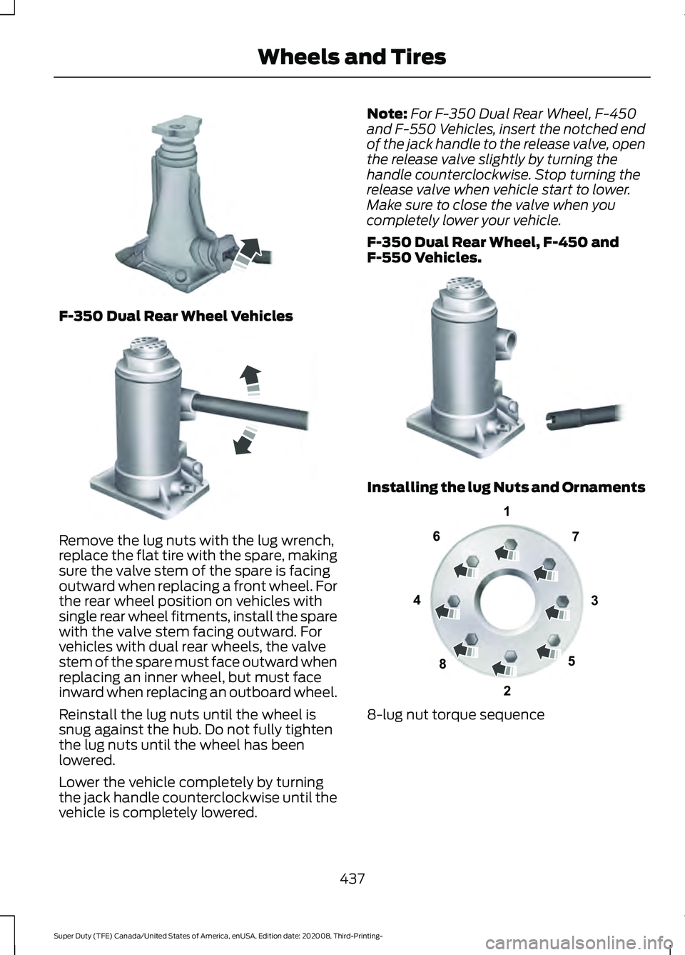
F-350 Dual Rear Wheel Vehicles
Remove the lug nuts with the lug wrench,
replace the flat tire with the spare, making
sure the valve stem of the spare is facing
outward when replacing a front wheel. For
the rear wheel position on vehicles with
single rear wheel fitments, install the spare
with the valve stem facing outward. For
vehicles with dual rear wheels, the valve
stem of the spare must face outward when
replacing an inner wheel, but must face
inward when replacing an outboard wheel.
Reinstall the lug nuts until the wheel is
snug against the hub. Do not fully tighten
the lug nuts until the wheel has been
lowered.
Lower the vehicle completely by turning
the jack handle counterclockwise until the
vehicle is completely lowered. Note:
For F-350 Dual Rear Wheel, F-450
and F-550 Vehicles, insert the notched end
of the jack handle to the release valve, open
the release valve slightly by turning the
handle counterclockwise. Stop turning the
release valve when vehicle start to lower.
Make sure to close the valve when you
completely lower your vehicle.
F-350 Dual Rear Wheel, F-450 and
F-550 Vehicles. Installing the lug Nuts and Ornaments
8-lug nut torque sequence
437
Super Duty (TFE) Canada/United States of America, enUSA, Edition date: 202008, Third-Printing- Wheels and TiresE162811 E162819 E162812 13
4
27
6
5
8E161441
Page 441 of 666

10-lug nut torque sequence
Note:
When installing the wheel center
ornaments, make sure that the ornament
retention towers on the back side of the
ornament are aligned with the studs or nuts
and retain to the flange on the lug nuts. Note:
For dual rear wheels, align the
ornament with the lug nuts. (A) is the clip
in the ornament and (B) is the flange of the
lug nut. Make sure that each of the retention
clips are sitting on a lug nut flange. Note:
If the ornament retention clips are
aligned between the studs or lug nuts, the
ornament will be improperly installed. This
improper installation may appear and sound
correct, but will not keep the ornament on
the vehicle. Ornaments improperly installed
in this manner may become loose or fall off
during driving. Use your hand or a rubber mallet to tap the
ornament until the retention clips snap
over the lug nut flanges. Tap in a star
pattern until the ornament seats fully onto
the wheel. There should be an even gap
between the ornament and the wheel
when it is properly installed.
438
Super Duty (TFE) Canada/United States of America, enUSA, Edition date: 202008, Third-Printing- Wheels and Tires1
2
3
4
5
6
7 8
9
10E169375 E162820 ABE162822 E162823
Page 442 of 666

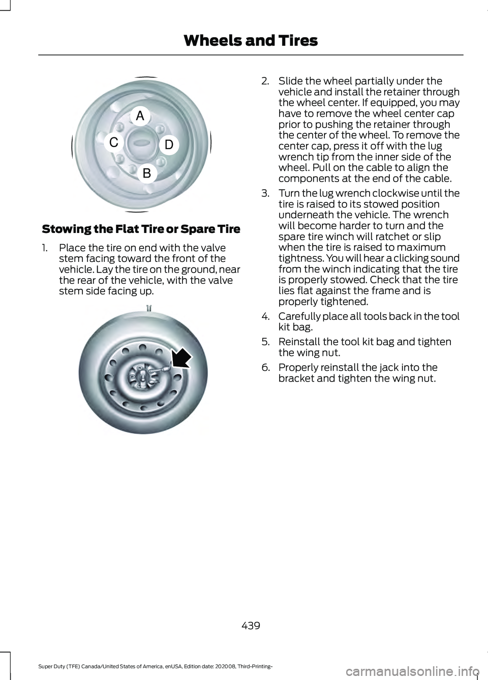
Stowing the Flat Tire or Spare Tire
1. Place the tire on end with the valve
stem facing toward the front of the
vehicle. Lay the tire on the ground, near
the rear of the vehicle, with the valve
stem side facing up. 2. Slide the wheel partially under the
vehicle and install the retainer through
the wheel center. If equipped, you may
have to remove the wheel center cap
prior to pushing the retainer through
the center of the wheel. To remove the
center cap, press it off with the lug
wrench tip from the inner side of the
wheel. Pull on the cable to align the
components at the end of the cable.
3. Turn the lug wrench clockwise until the
tire is raised to its stowed position
underneath the vehicle. The wrench
will become harder to turn and the
spare tire winch will ratchet or slip
when the tire is raised to maximum
tightness. You will hear a clicking sound
from the winch indicating that the tire
is properly stowed. Check that the tire
lies flat against the frame and is
properly tightened.
4. Carefully place all tools back in the tool
kit bag.
5. Reinstall the tool kit bag and tighten the wing nut.
6. Properly reinstall the jack into the bracket and tighten the wing nut.
439
Super Duty (TFE) Canada/United States of America, enUSA, Edition date: 202008, Third-Printing- Wheels and TiresA
C
B
DE162824 E162800
Page 443 of 666

TECHNICAL SPECIFICATIONS
Wheel Lug Nut Torque Specifications
WARNING: When you install a wheel, always remove any corrosion, dirt or foreign
materials present on the mounting surfaces of the wheel or the surface of the wheel
hub, brake drum or brake disc that contacts the wheel. Make sure to secure any fasteners
that attach the rotor to the hub so they do not interfere with the mounting surfaces of
the wheel. Installing wheels without correct metal-to-metal contact at the wheel
mounting surfaces can cause the wheel nuts to loosen and the wheel to come off while
your vehicle is in motion, resulting in loss of vehicle control, personal injury or death. lb.ft (Nm)
1
Bolt size
150 lb.ft (204 Nm)
M14 x 1.5
1 Torque specifications are for nut and bolt threads free of dirt and rust. Use only Ford
recommended replacement fasteners.
On vehicles equipped with single rear wheels, retighten the lug nuts to the specified torque
at 100 mi (160 km) after any wheel disturbance, such as tire rotation, changing a flat tire,
or wheel removal.
On vehicles equipped with dual rear wheels, retighten the wheel lug nuts to the specified
torque at
100 mi (160 km), and again at 500 mi (800 km) of new vehicle operation and
after any wheel disturbance, such as tire rotation, changing a flat tire, or wheel removal.
It is important to follow the proper wheel mounting and lug nut torque procedures. Wheel pilot bore
A
Inspect the wheel pilot hole and
mounting surface prior to installation.
Remove any visible corrosion or loose
particles.
440
Super Duty (TFE) Canada/United States of America, enUSA, Edition date: 202008, Third-Printing- Wheels and TiresE145950
Page 570 of 666

Check Every Month
Air filter restriction gauge. 1
Engine oil level.
Function of all interior and exterior lights.
Tires including the spare for wear and proper pressure. Windshield washer fluid level.
Fuel and water separator. Drain if necessary or if indicated by the information display. 1
Holes and slots in the tail pipe to make sure they are functional and clear of debris. 1
1 Diesel vehicles only. Check Every Six Months
Battery connections. Clean if necessary.
Body and door drain holes for obstructions. Clean if necessary. Cooling system fluid level and coolant strength.
Door weatherstrips for wear. Lubricate if necessary.
Hinges, latches and outside locks for proper operation. Lubricate if necessary. Parking brake for proper operation.
Safety belts and seat latches for wear and function.
Safety warning lamps, brake, ABS, airbag and safety belt for operation.
Washer spray and wiper operation. Clean or replace blades as necessary.
567
Super Duty (TFE) Canada/United States of America, enUSA, Edition date: 202008, Third-Printing- Scheduled Maintenance
Page 571 of 666

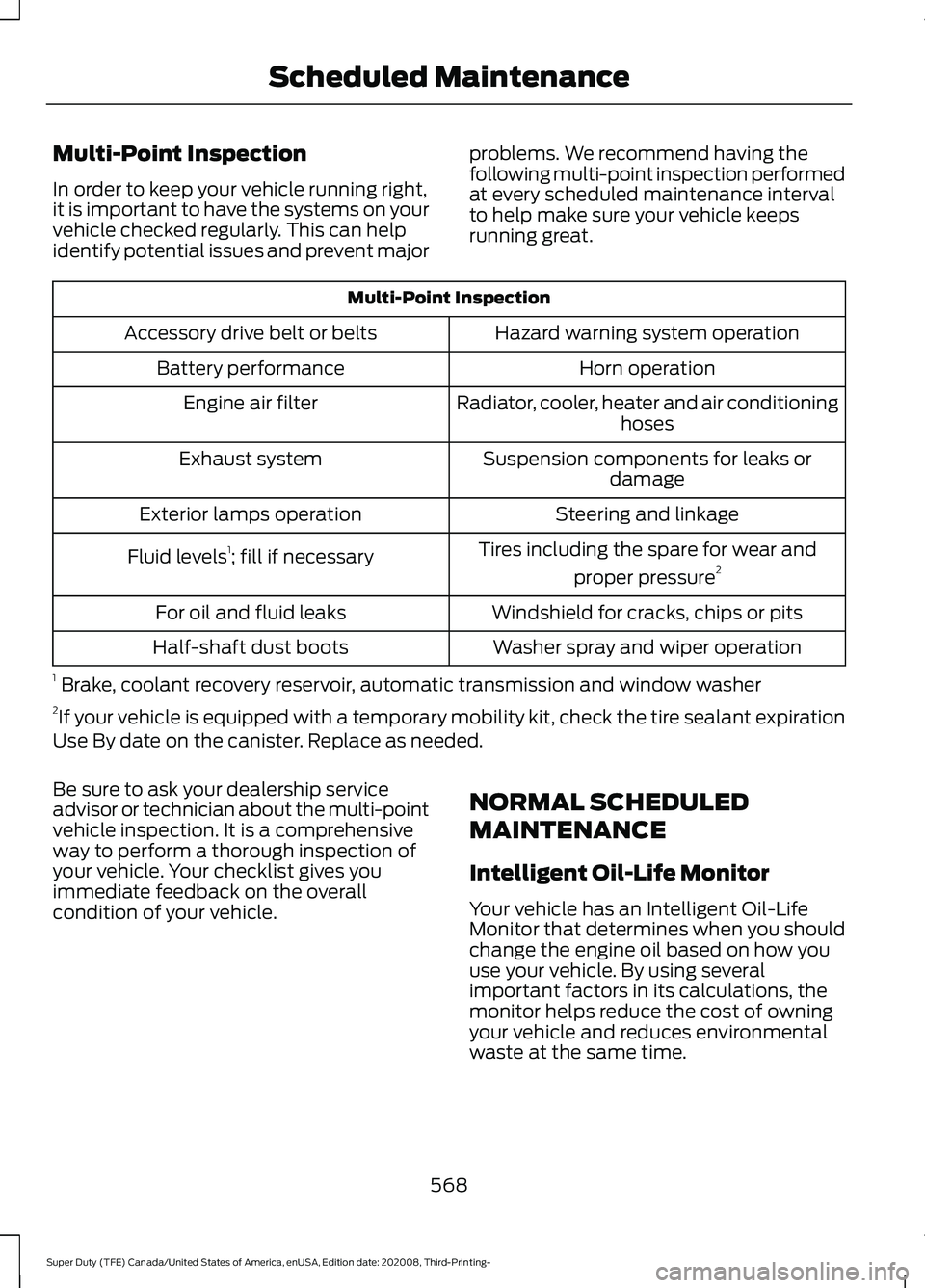
Multi-Point Inspection
In order to keep your vehicle running right,
it is important to have the systems on your
vehicle checked regularly. This can help
identify potential issues and prevent major
problems. We recommend having the
following multi-point inspection performed
at every scheduled maintenance interval
to help make sure your vehicle keeps
running great.Multi-Point Inspection
Hazard warning system operation
Accessory drive belt or belts
Horn operation
Battery performance
Radiator, cooler, heater and air conditioninghoses
Engine air filter
Suspension components for leaks ordamage
Exhaust system
Steering and linkage
Exterior lamps operation
Tires including the spare for wear andproper pressure 2
Fluid levels 1
; fill if necessary
Windshield for cracks, chips or pits
For oil and fluid leaks
Washer spray and wiper operation
Half-shaft dust boots
1 Brake, coolant recovery reservoir, automatic transmission and window washer
2 If your vehicle is equipped with a temporary mobility kit, check the tire sealant expiration
Use By date on the canister. Replace as needed.
Be sure to ask your dealership service
advisor or technician about the multi-point
vehicle inspection. It is a comprehensive
way to perform a thorough inspection of
your vehicle. Your checklist gives you
immediate feedback on the overall
condition of your vehicle. NORMAL SCHEDULED
MAINTENANCE
Intelligent Oil-Life Monitor
Your vehicle has an Intelligent Oil-Life
Monitor that determines when you should
change the engine oil based on how you
use your vehicle. By using several
important factors in its calculations, the
monitor helps reduce the cost of owning
your vehicle and reduces environmental
waste at the same time.
568
Super Duty (TFE) Canada/United States of America, enUSA, Edition date: 202008, Third-Printing- Scheduled Maintenance