2021 FORD F-550 ECU
[x] Cancel search: ECUPage 360 of 666

From the main menu scroll to:
Action and description
Message
Press the down arrow
button, then from this menu
scroll to the following
message.
Truck Info
Press the OK button.
Mainten-
ance
Monitor
Press the down arrow
button, then from this menu
scroll to the following
message.
Oil Life:
xxx%
Press the
OK button.
Oil Life
Press and hold the
OK
button until the instrument
cluster displays the
following message.
Oil Life
Hold OK to
Reset
Oil Life: 100%
When the oil change indic-
ator resets the instrument
cluster displays 100%.
Repeat the process if the oil
change indicator does not
reset.
CHANGING THE ENGINE AIR
FILTER - 6.2L WARNING:
To reduce the risk of
vehicle damage and personal burn
injuries, do not start your engine with the
air cleaner removed and do not remove
it while the engine is running.
Use the correct specification air filter
element. See
Motorcraft Parts (page
443). Note:
Failure to use the correct air filter
element may result in severe engine
damage. Resulting component damage
may not be covered by the vehicle Warranty.
Change the air filter element at the correct
service interval. See
Scheduled
Maintenance (page 565). 1. Disconnect the mass air flow sensor
electrical connector, if required.
2. Remove the air intake tube securing clamp.
3. Pull the air intake tube away from the air filter housing.
4. Remove the clips that secure the air filter housing cover. Remove the air
filter housing cover.
357
Super Duty (TFE) Canada/United States of America, enUSA, Edition date: 202008, Third-Printing- MaintenanceE226426
x4
1
2
4
3
Page 361 of 666

5.
Remove the air filter element from the
air filter housing.
6. Install in the reverse order.
CHANGING THE ENGINE AIR
FILTER - 6.7L DIESEL WARNING: To reduce the risk of
vehicle damage and personal burn
injuries, do not start your engine with the
air cleaner removed and do not remove
it while the engine is running.
Use the correct specification air filter
element. See
Motorcraft Parts (page
443).
Note: Failure to use the correct air filter
element may result in severe engine
damage. Resulting component damage
may not be covered by the vehicle Warranty.
Change the air filter element at the correct
service interval. See
Scheduled
Maintenance (page 565). 1. Disconnect the mass air flow sensor
electrical connector, if required.
2. Remove the clips (x3) that secure the air filter housing cover. Remove the air
filter housing cover. Disconnect and
pull the air intake tube away, as
needed. 3.
Remove the air filter element from the
air filter housing.
358
Super Duty (TFE) Canada/United States of America, enUSA, Edition date: 202008, Third-Printing- MaintenanceE226427
5 E310318 E310319
Page 364 of 666

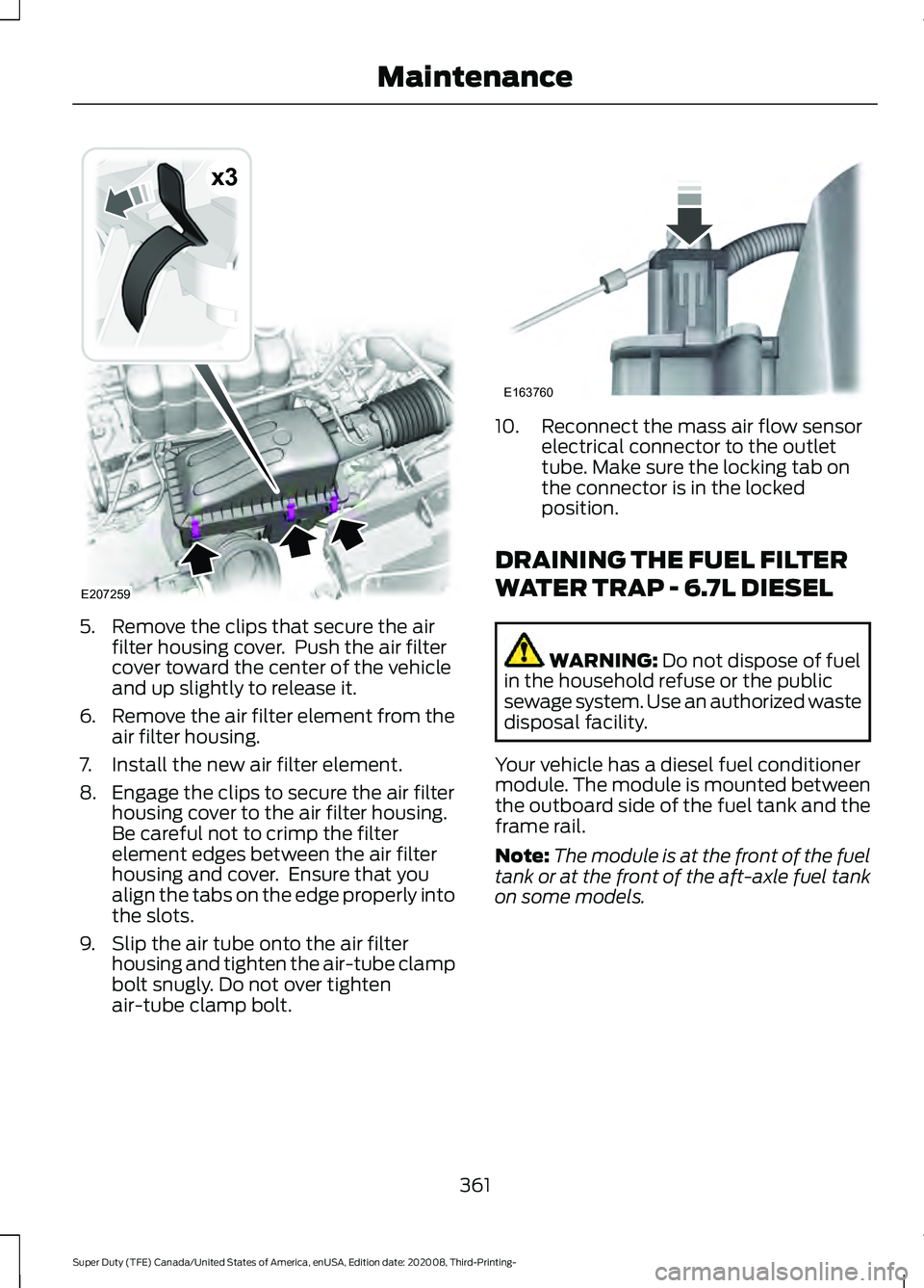
5. Remove the clips that secure the air
filter housing cover. Push the air filter
cover toward the center of the vehicle
and up slightly to release it.
6. Remove the air filter element from the
air filter housing.
7. Install the new air filter element.
8. Engage the clips to secure the air filter housing cover to the air filter housing.
Be careful not to crimp the filter
element edges between the air filter
housing and cover. Ensure that you
align the tabs on the edge properly into
the slots.
9. Slip the air tube onto the air filter housing and tighten the air-tube clamp
bolt snugly. Do not over tighten
air-tube clamp bolt. 10. Reconnect the mass air flow sensor
electrical connector to the outlet
tube. Make sure the locking tab on
the connector is in the locked
position.
DRAINING THE FUEL FILTER
WATER TRAP - 6.7L DIESEL WARNING: Do not dispose of fuel
in the household refuse or the public
sewage system. Use an authorized waste
disposal facility.
Your vehicle has a diesel fuel conditioner
module. The module is mounted between
the outboard side of the fuel tank and the
frame rail.
Note: The module is at the front of the fuel
tank or at the front of the aft-axle fuel tank
on some models.
361
Super Duty (TFE) Canada/United States of America, enUSA, Edition date: 202008, Third-Printing- MaintenanceE207259
x3 E163760
Page 391 of 666

3. Drain the diesel fuel conditioner
module. Turn the drain plug
counterclockwise until it stops. Do not
use any tools to loosen the drain plug.
Drain the filter, approximately 0.53 gal
(2 L), into an appropriate container.
Do not re-use the fuel drained from the
module. 4. Disconnect the electrical connector.
5. Fully loosen the bolts securing the
lower portion of the diesel fuel
conditioner module housing.
Note: Do not fully remove the bolts from
the lower portion of the diesel fuel
conditioner module housing.
6. Remove the lower portion of the diesel
fuel conditioner module housing. 7. Slide the filter element toward the
drain plug to disengage the securing
clips.
Installation
1. Slide the filter element into the housing
and fully engage the securing clips.
2. Install the lower portion of the housing.
Tighten the bolts until you feel a strong
resistance. Maximum torque
7 lb.ft
(9 Nm).
3. Connect the electrical connector.
4. Tighten the drain plug, turn it clockwise
until it stops and you feel a strong
resistance. Do not use any tools to
tighten the drain plug.
388
Super Duty (TFE) Canada/United States of America, enUSA, Edition date: 202008, Third-Printing- MaintenanceE269861 E269862 E269863
Page 424 of 666

non-recommended tires and wheels can
cause steering, suspension, axle, transfer
case or power transfer unit failure.
Follow the Ford recommended tire
inflation pressure found on the Safety
Compliance Certification Label (on the
door hinge pillar, door latch post or the
door edge that meets the door latch
post, next to the driver seat), or Tire
Label on the B-Pillar or the edge of the
driver door. Failure to follow the tire
pressure recommendations can cause
uneven treadwear patterns and
adversely affect the way your vehicle
handles.
WARNING: Do not use snow chains
on snow-free roads.
Note: Do not use snow chains on vehicles
with LT275/65R20 or LT 285/75R18 sized
tires.
The tires on your vehicle have all-weather
treads to provide traction in rain and snow.
However, in some climates, you may need
to use snow tires and cables. If you need
to use cables, we recommend that you use
steel wheels of the same size and
specification, as cables may chip
aluminum wheels.
Note: The suspension insulation and
bumpers will help prevent vehicle damage.
Do not remove these components from your
vehicle when using snow tires and chains.
Follow these guidelines when using snow
tires and chains:
• If possible, avoid fully loading your
vehicle.
• Use only SAE Class S chains.
• Install chains securely, verifying that
the chains do not touch any wiring,
brake lines or fuel lines.
• Only install snow chains on the rear
axle. •
For Dual Rear Wheel (DRW) vehicles,
only install snow chains on the outer
wheel of each pair.
• Drive cautiously. If you hear the chains
rub or bang against your vehicle, stop
and retighten the chains. If this does
not work, remove the chains to prevent
damage to your vehicle.
• Remove the tire chains when you no
longer need them. Do not use tire
chains on dry roads.
If you have any questions regarding snow
chains or cables, please contact your
authorized dealer.
TIRE PRESSURE MONITORING
SYSTEM
Vehicle Tire Pressure Monitoring
System WARNING:
The tire pressure
monitoring system is not a substitute for
manually checking tire pressures. You
should periodically check tire pressures
using a pressure gauge. Failure to
correctly maintain tire pressures could
increase the risk of tire failure, loss of
control, vehicle rollover and personal
injury. Check each tire, including the
spare, if provided, monthly when
cold and inflated to the inflation
pressure recommended by the vehicle
manufacturer on the vehicle placard or tire
inflation pressure label. If your vehicle has
tires of a different size than the size
indicated on the vehicle placard or tire
inflation pressure label, you should
determine the proper tire inflation pressure
for those tires.
421
Super Duty (TFE) Canada/United States of America, enUSA, Edition date: 202008, Third-Printing- Wheels and Tires
Page 434 of 666

WARNING: To help prevent your
vehicle from moving when changing a
wheel, shift the transmission into park
(P), set the parking brake and use an
appropriate block or wheel chock to
secure the wheel diagonally opposite to
the wheel being changed. For example,
when changing the front left wheel,
place an appropriate block or wheel
chock on the right rear wheel. WARNING:
Always use the jack
provided as original equipment with your
vehicle. If using a jack other than the one
provided, make sure the jack capacity is
adequate for the vehicle weight,
including any vehicle cargo or
modifications. If you are unsure if the jack
capacity is adequate, contact the
authorized dealer. WARNING:
Failure to follow these
guidelines could result in an increased
risk of loss of vehicle control, injury or
death. WARNING:
Never place anything
between the vehicle jack and your
vehicle. WARNING:
Never place anything
between the vehicle jack and the ground. WARNING:
Park your vehicle so
that you do not obstruct the flow of
traffic or place yourself in any danger and
set up a warning triangle. WARNING:
Do not work on your
vehicle when the jack is the only support
as your vehicle could slip off the jack.
Failure to follow this instruction could
result in personal injury or death. WARNING:
Do not get under a
vehicle that is only supported by a
vehicle jack. WARNING:
Do not attempt to
change a tire on the side of the vehicle
close to moving traffic. Pull far enough
off the road to avoid the danger of being
hit when operating the jack or changing
the wheel. WARNING:
Only use the spare
wheel carrier to stow the wheel provided
with your vehicle. Other wheel sizes
could cause the spare wheel carrier to
fail if it does not fit securely or is too
heavy.
Note: Do not use impact tools or power
tools operating at over 200 RPM on the
spare wheel carrier winch, which may cause
it to malfunction and prevent a secure fit.
Override the winch at least three times
(there is an audible click each time) to make
sure the wheel and tire fit securely.
Note: Passengers should not remain in the
vehicle when the vehicle is being jacked.
1. Park the vehicle on a level firm ground and activate the hazard flashers.
2. Apply the parking brake, place the transmission in park (P), switch the
engine off.
3. Block the wheel diagonally opposite the flat tire. For example, if the left
front tire is flat, block the right rear
wheel.
431
Super Duty (TFE) Canada/United States of America, enUSA, Edition date: 202008, Third-Printing- Wheels and Tires
Page 443 of 666

TECHNICAL SPECIFICATIONS
Wheel Lug Nut Torque Specifications
WARNING: When you install a wheel, always remove any corrosion, dirt or foreign
materials present on the mounting surfaces of the wheel or the surface of the wheel
hub, brake drum or brake disc that contacts the wheel. Make sure to secure any fasteners
that attach the rotor to the hub so they do not interfere with the mounting surfaces of
the wheel. Installing wheels without correct metal-to-metal contact at the wheel
mounting surfaces can cause the wheel nuts to loosen and the wheel to come off while
your vehicle is in motion, resulting in loss of vehicle control, personal injury or death. lb.ft (Nm)
1
Bolt size
150 lb.ft (204 Nm)
M14 x 1.5
1 Torque specifications are for nut and bolt threads free of dirt and rust. Use only Ford
recommended replacement fasteners.
On vehicles equipped with single rear wheels, retighten the lug nuts to the specified torque
at 100 mi (160 km) after any wheel disturbance, such as tire rotation, changing a flat tire,
or wheel removal.
On vehicles equipped with dual rear wheels, retighten the wheel lug nuts to the specified
torque at
100 mi (160 km), and again at 500 mi (800 km) of new vehicle operation and
after any wheel disturbance, such as tire rotation, changing a flat tire, or wheel removal.
It is important to follow the proper wheel mounting and lug nut torque procedures. Wheel pilot bore
A
Inspect the wheel pilot hole and
mounting surface prior to installation.
Remove any visible corrosion or loose
particles.
440
Super Duty (TFE) Canada/United States of America, enUSA, Edition date: 202008, Third-Printing- Wheels and TiresE145950
Page 477 of 666

CONNECTED VEHICLE
REQUIREMENTS
Connected service and related feature
functionality requires a compatible vehicle
network.
Some remote features require additional
service activation. Log in to your Ford
account for details. Some restrictions, third
party terms and message or data rates
may apply.
CONNECTED VEHICLE
LIMITATIONS
Evolving technology, cellular networks, or
regulations could affect functionality and
availability, or continued provision of some
features. These changes could even stop
some features from functioning.
CONNECTING THE VEHICLE TO
A MOBILE NETWORK
What Is the Modem
The modem allows access to a
range of features built into your
vehicle.
Enabling and Disabling the Modem
1. Press Settings. 2. Press
FordPass Connect.
3. Press
Connectivity Settings.
4. Switch connectivity features on or off.
Connecting FordPass to the
Modem
1. Make sure that the modem is enabled using the vehicle settings menu.
2. Open the FordPass app on your device
and log in.
3. Add your vehicle or select your vehicle if already added.
4. Select the option for vehicle details.
5. Select the option to activate your vehicle.
6. Make sure that the name on the screen
matches the name shown in your
FordPass account.
7. Confirm that FordPass account is connected to the modem.
CONNECTING THE VEHICLE TO
A WI-FI NETWORK
1. Press
Settings.
2. Press
Wi-Fi.
3. Switch
Wi-Fi on.
4. Press
View Available Networks.
5. Select an available Wi-Fi network.
Note: Enter the network password to
connect to a secure network.
474
Super Duty (TFE) Canada/United States of America, enUSA, Edition date: 202008, Third-Printing- Connected Vehicle