2021 FORD F-550 tailgate
[x] Cancel search: tailgatePage 282 of 666
PICKUP BED RAMPS (If
Equipped)
Pickup Bed Ramp Precautions
WARNING: When sliding the ramp
up or down, take care not to get your
fingers or hands caught in the
mechanism. Failure to follow this
instruction could result in personal injury. WARNING:
Make sure that you
correctly install the ramp to the tailgate
plate. Failure to follow this instruction
could result in personal injury. WARNING:
Do not step or sit on
the ramp when it is in the stowed
position. Failure to follow this instruction
could result in personal injury. WARNING:
Only install the ramp
within the prescribed ramp angles.
Failure to follow this instruction could
result in personal injury.
Note: Each pickup bed ramp has a
maximum capacity of
400 lb (181.4 kg).
Note: Verify the ramp is on stable ground
before usage.
Note: For loading and unloading
equipment, your ramp should be set
between 10 degrees upward and 26 degrees
downward to avoid damage to the ramp
claw and tailgate plate.
Note: When using your vehicle for off-road
operation, remove the bed ramps from the
vehicle and store them in a safe location
away from your vehicle. Installing and Removing the
Pickup Bed Ramp Holder
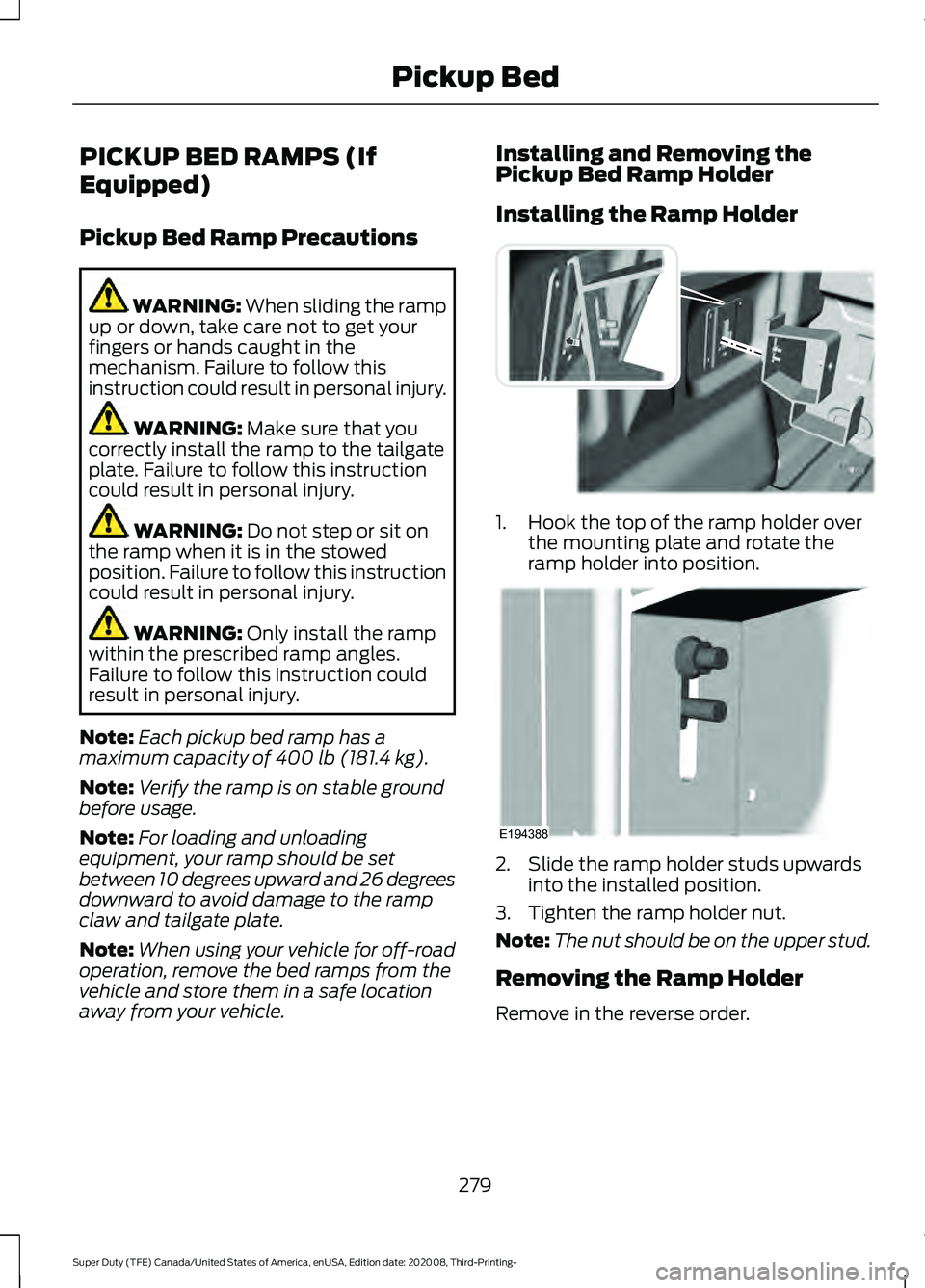
Installing the Ramp Holder
1. Hook the top of the ramp holder over
the mounting plate and rotate the
ramp holder into position. 2. Slide the ramp holder studs upwards
into the installed position.
3. Tighten the ramp holder nut.
Note: The nut should be on the upper stud.
Removing the Ramp Holder
Remove in the reverse order.
279
Super Duty (TFE) Canada/United States of America, enUSA, Edition date: 202008, Third-Printing- Pickup BedE194387 E194388
Page 283 of 666
Installing and Removing the
Pickup Bed Ramps
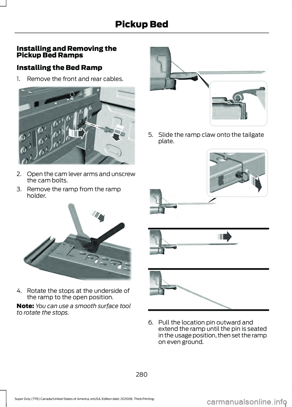
Installing the Bed Ramp
1. Remove the front and rear cables.
2.
Open the cam lever arms and unscrew
the cam bolts.
3. Remove the ramp from the ramp holder. 4. Rotate the stops at the underside of
the ramp to the open position.
Note: You can use a smooth surface tool
to rotate the stops. 5. Slide the ramp claw onto the tailgate
plate. 6. Pull the location pin outward and
extend the ramp until the pin is seated
in the usage position, then set the ramp
on even ground.
280
Super Duty (TFE) Canada/United States of America, enUSA, Edition date: 202008, Third-Printing- Pickup BedE194380 E211150 E194382 E194383
Page 284 of 666
Removing the Ramp
Remove in the reverse order.
Storing the Pickup Bed Ramps
Storing the Bed Ramp
1. Pick up the ramp. Pull the location pin
outward.
2. Slide the ramp into the storage position
until the location pin locks.
Note: Make sure the proper pin location has
been applied for your bed size.
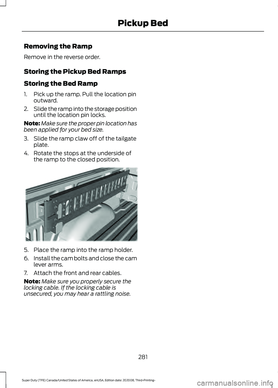
3. Slide the ramp claw off of the tailgate plate.
4. Rotate the stops at the underside of the ramp to the closed position. 5. Place the ramp into the ramp holder.
6.
Install the cam bolts and close the cam
lever arms.
7. Attach the front and rear cables.
Note: Make sure you properly secure the
locking cable. If the locking cable is
unsecured, you may hear a rattling noise.
281
Super Duty (TFE) Canada/United States of America, enUSA, Edition date: 202008, Third-Printing- Pickup BedE194391
Page 290 of 666
Note:
Use consistent metric or imperial
units as required by your country or vehicle.
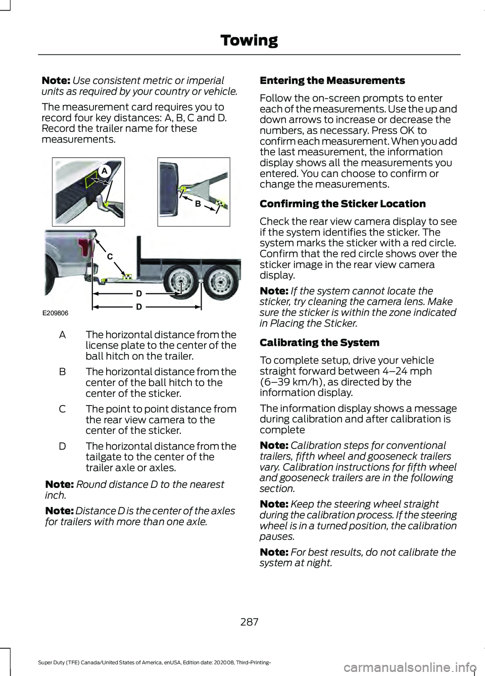
The measurement card requires you to
record four key distances: A, B, C and D.
Record the trailer name for these
measurements. The horizontal distance from the
license plate to the center of the
ball hitch on the trailer.
A
The horizontal distance from the
center of the ball hitch to the
center of the sticker.
B
The point to point distance from
the rear view camera to the
center of the sticker.
C
The horizontal distance from the
tailgate to the center of the
trailer axle or axles.
D
Note: Round distance D to the nearest
inch.
Note: Distance D is the center of the axles
for trailers with more than one axle. Entering the Measurements
Follow the on-screen prompts to enter
each of the measurements. Use the up and
down arrows to increase or decrease the
numbers, as necessary. Press OK to
confirm each measurement. When you add
the last measurement, the information
display shows all the measurements you
entered. You can choose to confirm or
change the measurements.
Confirming the Sticker Location
Check the rear view camera display to see
if the system identifies the sticker. The
system marks the sticker with a red circle.
Confirm that the red circle shows over the
sticker image in the rear view camera
display.
Note:
If the system cannot locate the
sticker, try cleaning the camera lens. Make
sure the sticker is within the zone indicated
in Placing the Sticker.
Calibrating the System
To complete setup, drive your vehicle
straight forward between 4– 24 mph
(6– 39 km/h), as directed by the
information display.
The information display shows a message
during calibration and after calibration is
complete
Note: Calibration steps for conventional
trailers, fifth wheel and gooseneck trailers
vary. Calibration instructions for fifth wheel
and gooseneck trailers are in the following
section.
Note: Keep the steering wheel straight
during the calibration process. If the steering
wheel is in a turned position, the calibration
pauses.
Note: For best results, do not calibrate the
system at night.
287
Super Duty (TFE) Canada/United States of America, enUSA, Edition date: 202008, Third-Printing- TowingE209806
A
B
C
D
D
Page 296 of 666
Measurement B has reached maximum or
minimum value:
•
Make sure that the sticker placement
instruction in step 3 of the setup has
been followed. Stickers placed outside
the allowed zone adversely affects the
system performance and could cause
improper feature function.
• Make sure that the measurement being
made is the horizontal distance only
from center of sticker to the hitch ball
center. A straight line distance that
includes any vertical rise or drop
increases the measurement and
causes an inaccurate value to be
entered into the system. See step 4 of
the setup for additional measurement
instructions.
Measurement C has reached maximum or
minimum value:
• Make sure you follow the sticker
placement instructions in step 3 of the
setup. Stickers placed outside the
allowed zone adversely affect the
system performance and could cause
improper feature function. If you have
met all the criteria for sticker
placement and you see this message,
the sticker is either too far below or too
close to the camera to properly
recognize the sticker. For the system
to operate correctly, the sticker height
must be lowered if you receive the
minimum warning or the sticker height
must be raised if you receive the
maximum warning.
• Only one sticker can be placed on the
trailer for correct system function. The
previous sticker must be removed or
covered so only one sticker is visible to
the camera.
• Measurement B and C must be
measured again if a new sticker is
placed on the trailer. Measurement D has reached maximum or
minimum value:
•
Make sure that the measurement being
made is the horizontal distance only
from tailgate to the center of the single
axle or the center of all the axles on the
trailer. See step 4 of the setup for
additional measurement instructions.
The system does not support trailer
lengths outside the range allowed by
the information display.
System is circling something beside the
sticker or system cannot find the sticker:
• Make sure the rear camera is clean and
the sticker is clearly visible in the
camera image. Clean the camera and
sticker if necessary.
• The camera system uses the entered
measurements to help locate the
sticker. Inaccurate sticker
measurements degrade the system ’s
ability to locate the sticker. Verify the
measurements you enter into the
system are accurate.
• Remove the incorrectly circled label or
decal if possible.
• If you cannot resolve the issue, try a
new sticker location. The sticker
location must still meet the
requirements noted in step 3 of the
setup instructions. Only one sticker can
be placed on the trailer for correct
system function. The previous sticker
must be removed or covered so only
one sticker is visible to the camera.
Calibration
The system monitors various vehicle
parameters to ensure your vehicle is being
driven straight and the trailer is straight
behind your vehicle. Any steering input or
trailer movement pauses the calibration.
293
Super Duty (TFE) Canada/United States of America, enUSA, Edition date: 202008, Third-Printing- Towing
Page 344 of 666
Protected Component
Fuse
Rating
Fuse
Number
Trailer tow battery charge.
30 A
26
Rear heated seats.
20 A
27
Glow plug (diesel).
25 A
28
Not used (gas).
—
Electric power assisted steering motor.
40 A
29
Not used (spare).
10 A
30
Power point 5.
20 A
31
Four-wheel drive module.
25 A
32
Alternator sense line 2.
10 A
33
Electric cooling fan (gas).
50 A
34
Supplemental air heater (diesel).
Power point 2.
20 A
35
Power point 1.
20 A
36
Anti-lock brake system pump.
60 A
37
Inverter.
60 A
38
Four-wheel drive module.
25 A
39
Starter motor solenoid.
30 A
40
Tailgate release solenoid.
10 A
41
Blower motor.
40 A
42
Trailer tow backup lamps.
10 A
43
Trailer tow lighting module.
40 A
44
Anti-lock brake system valve.
30 A
45
Compressed natural gas module power.
30 A
46
Supplemental air heater (diesel).
50 A
47
Not used (gas).
—
Supplemental air heater (diesel).
50 A
48
Not used (gas).
—
341
Super Duty (TFE) Canada/United States of America, enUSA, Edition date: 202008, Third-Printing- Fuses
Page 387 of 666

1.
Switch all of the lamps and the ignition
off.
2. Disconnect the electrical connector.
3. Turn the bulb holder counterclockwise
and remove it.
Note: You cannot separate the bulb from
the bulb holder.
Note: Handle a halogen headlamp bulb
carefully and keep out of children ’s reach.
Grasp the bulb only by its plastic base and
do not touch the glass. The oil from your
hand could cause the bulb to break the next
time the headlamps are operated.
Fog Lamp Bulbs (If Equipped) 1.
Switch all of the lamps and the ignition
off.
2. To access the bulb, reach behind the bumper.
3. Disconnect the electrical connector.
4. Turn the bulb holder counterclockwise
and remove it.
Note: You cannot separate the bulb from
the bulb holder.
Note: Handle a halogen bulb carefully and
keep out of children ’s reach. Grasp the bulb
only by its plastic base and do not touch the
glass. The oil from your hand could cause
the bulb to break the next time the fog
lamps are operated.
Rear Lamps, Brake Lamps, Rear
Direction Indicator and Reversing
Lamp Bulbs
Pickup Models - Vehicles without Blind
Spot Information System 1.
Switch all of the lamps and the ignition
off.
2. Open the tailgate to expose the lamp assemblies.
384
Super Duty (TFE) Canada/United States of America, enUSA, Edition date: 202008, Third-Printing- MaintenanceE224991 E163826 E223775
5
Page 388 of 666
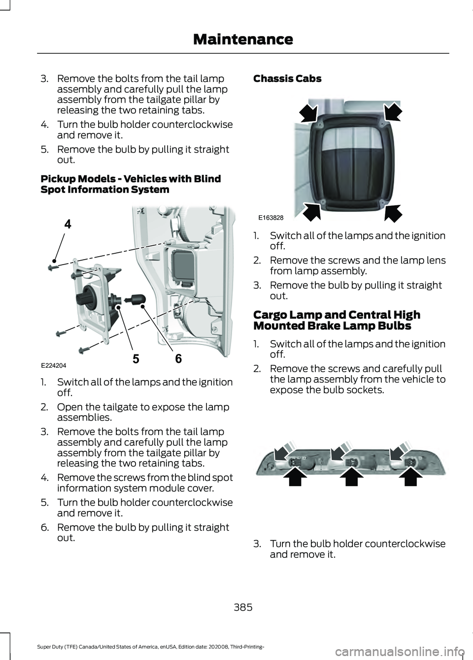
3. Remove the bolts from the tail lamp
assembly and carefully pull the lamp
assembly from the tailgate pillar by
releasing the two retaining tabs.
4. Turn the bulb holder counterclockwise
and remove it.
5. Remove the bulb by pulling it straight out.
Pickup Models - Vehicles with Blind
Spot Information System 1.
Switch all of the lamps and the ignition
off.
2. Open the tailgate to expose the lamp assemblies.
3. Remove the bolts from the tail lamp assembly and carefully pull the lamp
assembly from the tailgate pillar by
releasing the two retaining tabs.
4. Remove the screws from the blind spot
information system module cover.
5. Turn the bulb holder counterclockwise
and remove it.
6. Remove the bulb by pulling it straight out. Chassis Cabs
1.
Switch all of the lamps and the ignition
off.
2. Remove the screws and the lamp lens from lamp assembly.
3. Remove the bulb by pulling it straight out.
Cargo Lamp and Central High
Mounted Brake Lamp Bulbs
1. Switch all of the lamps and the ignition
off.
2. Remove the screws and carefully pull the lamp assembly from the vehicle to
expose the bulb sockets. 3.
Turn the bulb holder counterclockwise
and remove it.
385
Super Duty (TFE) Canada/United States of America, enUSA, Edition date: 202008, Third-Printing- MaintenanceE224204
4
65 E163828 E187290