2021 FORD F-350 length
[x] Cancel search: lengthPage 289 of 666
Placing the Sticker
You must place the sticker in an area
visible by the rear view camera.
Note:
The cargo and trailer hookup lamps
turn on to improve visibility.
Note: An assistant can help to carry out the
following procedure.
Note: Make sure nothing can obstruct the
rear view camera's view of the sticker. For
example, items such as a jack handle or
wiring.
Note: Position the sticker on a flat, dry and
clean horizontal surface. For best results,
apply the sticker when temperatures are
above 32°F (0°C).
Note: Do not move stickers after placing
them. Do not re-use any stickers if removed.
Note: You can purchase additional stickers
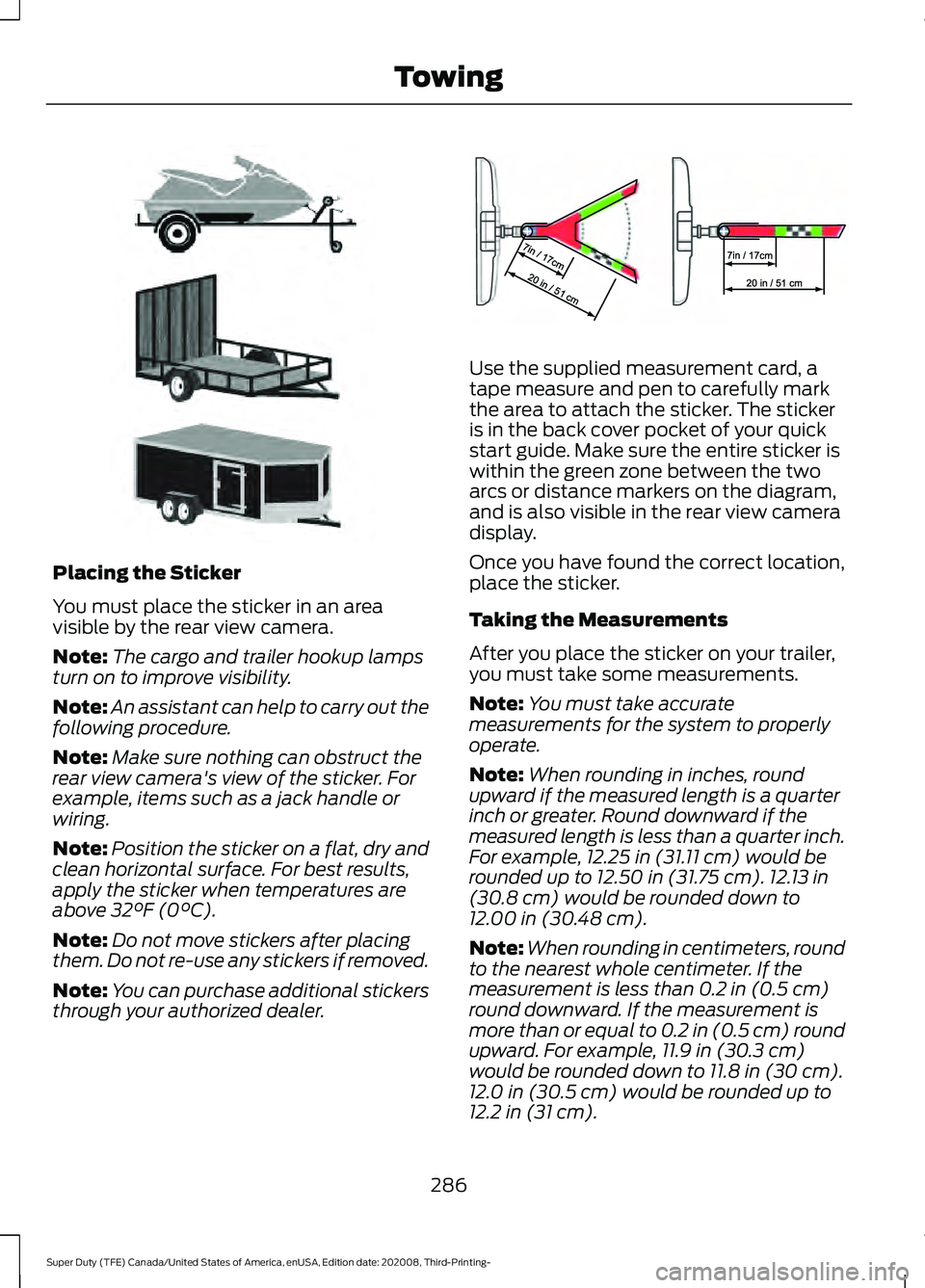
through your authorized dealer. Use the supplied measurement card, a
tape measure and pen to carefully mark
the area to attach the sticker. The sticker
is in the back cover pocket of your quick
start guide. Make sure the entire sticker is
within the green zone between the two
arcs or distance markers on the diagram,
and is also visible in the rear view camera
display.
Once you have found the correct location,
place the sticker.
Taking the Measurements
After you place the sticker on your trailer,
you must take some measurements.
Note:
You must take accurate
measurements for the system to properly
operate.
Note: When rounding in inches, round
upward if the measured length is a quarter
inch or greater. Round downward if the
measured length is less than a quarter inch.
For example, 12.25 in (31.11 cm)
would be
rounded up to 12.50 in (31.75 cm). 12.13 in
(30.8 cm) would be rounded down to
12.00 in (30.48 cm).
Note: When rounding in centimeters, round
to the nearest whole centimeter. If the
measurement is less than
0.2 in (0.5 cm)
round downward. If the measurement is
more than or equal to 0.2 in (0.5 cm) round
upward. For example, 11.9 in (30.3 cm)
would be rounded down to
11.8 in (30 cm).
12.0 in (30.5 cm) would be rounded up to
12.2 in (31 cm).
286
Super Duty (TFE) Canada/United States of America, enUSA, Edition date: 202008, Third-Printing- TowingE311876 E310619
Page 291 of 666
Fifth Wheel and Gooseneck Trailer
Setup (If Equipped)
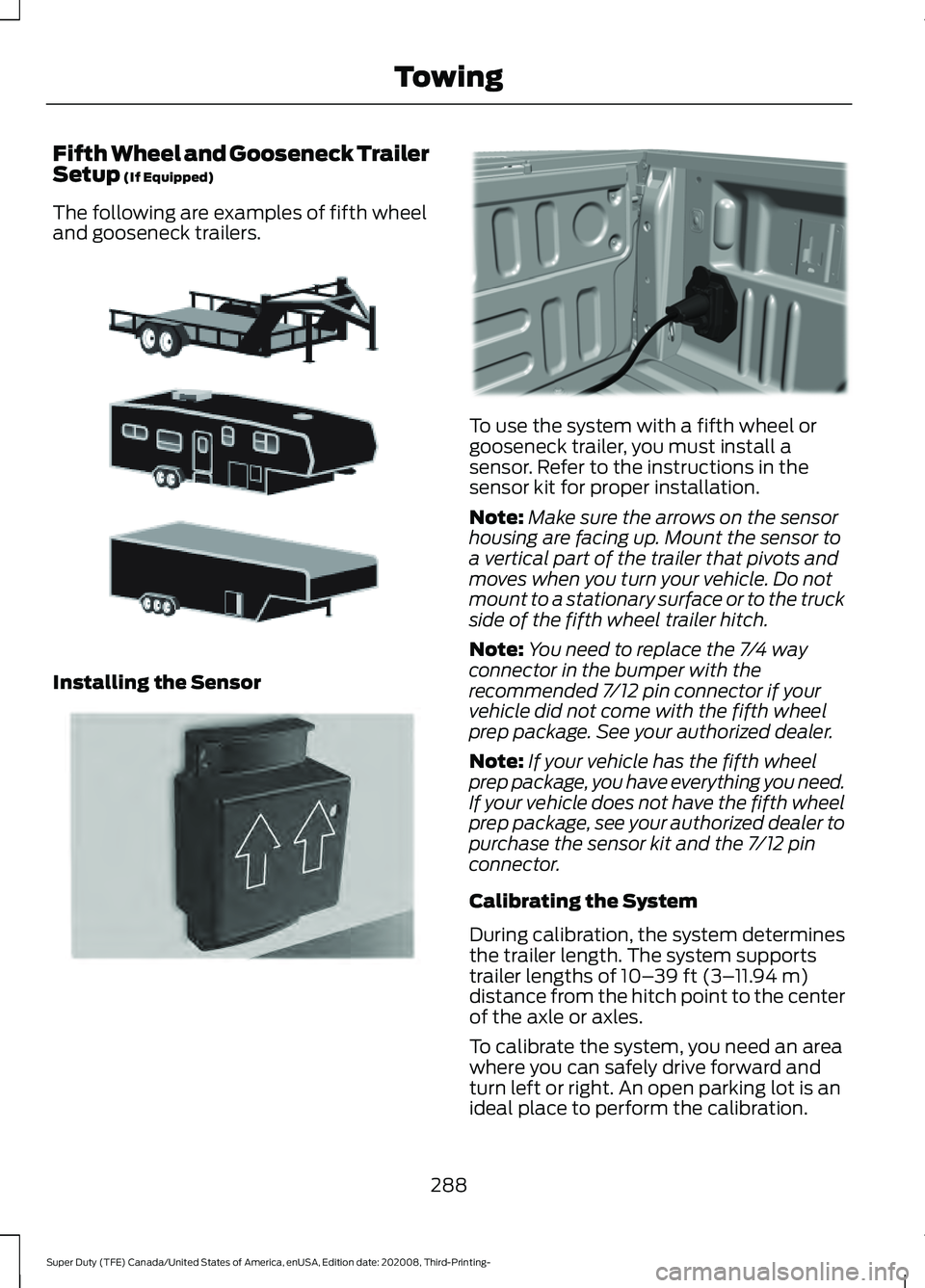
The following are examples of fifth wheel
and gooseneck trailers. Installing the Sensor To use the system with a fifth wheel or
gooseneck trailer, you must install a
sensor. Refer to the instructions in the
sensor kit for proper installation.
Note:
Make sure the arrows on the sensor
housing are facing up. Mount the sensor to
a vertical part of the trailer that pivots and
moves when you turn your vehicle. Do not
mount to a stationary surface or to the truck
side of the fifth wheel trailer hitch.
Note: You need to replace the 7/4 way
connector in the bumper with the
recommended 7/12 pin connector if your
vehicle did not come with the fifth wheel
prep package. See your authorized dealer.
Note: If your vehicle has the fifth wheel
prep package, you have everything you need.
If your vehicle does not have the fifth wheel
prep package, see your authorized dealer to
purchase the sensor kit and the 7/12 pin
connector.
Calibrating the System
During calibration, the system determines
the trailer length. The system supports
trailer lengths of
10– 39 ft (3– 11.94 m)
distance from the hitch point to the center
of the axle or axles.
To calibrate the system, you need an area
where you can safely drive forward and
turn left or right. An open parking lot is an
ideal place to perform the calibration.
288
Super Duty (TFE) Canada/United States of America, enUSA, Edition date: 202008, Third-Printing- TowingE311877 E315959 E316145
Page 295 of 666
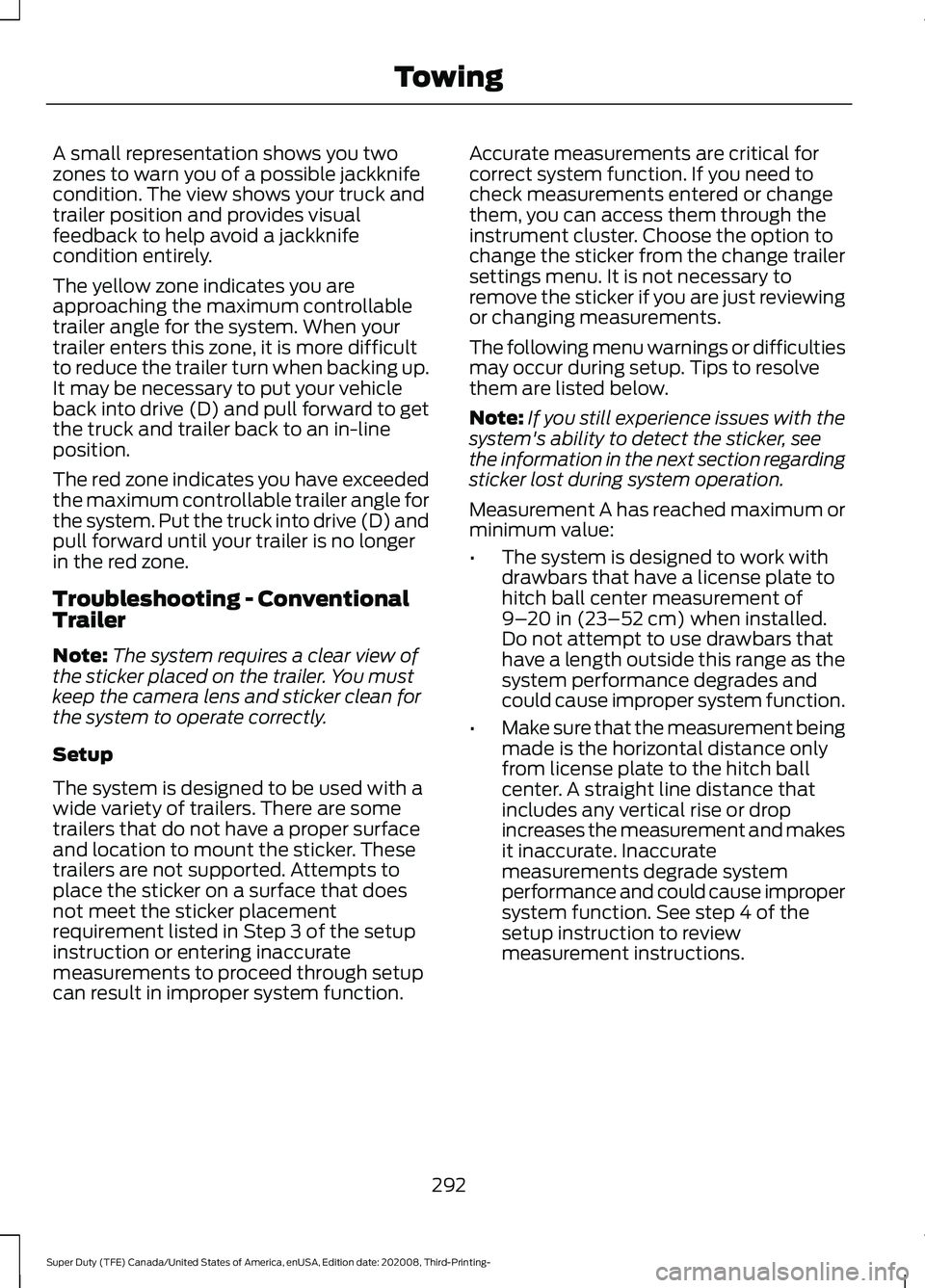
A small representation shows you two
zones to warn you of a possible jackknife
condition. The view shows your truck and
trailer position and provides visual
feedback to help avoid a jackknife
condition entirely.
The yellow zone indicates you are
approaching the maximum controllable
trailer angle for the system. When your
trailer enters this zone, it is more difficult
to reduce the trailer turn when backing up.
It may be necessary to put your vehicle
back into drive (D) and pull forward to get
the truck and trailer back to an in-line
position.
The red zone indicates you have exceeded
the maximum controllable trailer angle for
the system. Put the truck into drive (D) and
pull forward until your trailer is no longer
in the red zone.
Troubleshooting - Conventional
Trailer
Note:
The system requires a clear view of
the sticker placed on the trailer. You must
keep the camera lens and sticker clean for
the system to operate correctly.
Setup
The system is designed to be used with a
wide variety of trailers. There are some
trailers that do not have a proper surface
and location to mount the sticker. These
trailers are not supported. Attempts to
place the sticker on a surface that does
not meet the sticker placement
requirement listed in Step 3 of the setup
instruction or entering inaccurate
measurements to proceed through setup
can result in improper system function. Accurate measurements are critical for
correct system function. If you need to
check measurements entered or change
them, you can access them through the
instrument cluster. Choose the option to
change the sticker from the change trailer
settings menu. It is not necessary to
remove the sticker if you are just reviewing
or changing measurements.
The following menu warnings or difficulties
may occur during setup. Tips to resolve
them are listed below.
Note:
If you still experience issues with the
system's ability to detect the sticker, see
the information in the next section regarding
sticker lost during system operation.
Measurement A has reached maximum or
minimum value:
• The system is designed to work with
drawbars that have a license plate to
hitch ball center measurement of
9–20 in (23–52 cm) when installed.
Do not attempt to use drawbars that
have a length outside this range as the
system performance degrades and
could cause improper system function.
• Make sure that the measurement being
made is the horizontal distance only
from license plate to the hitch ball
center. A straight line distance that
includes any vertical rise or drop
increases the measurement and makes
it inaccurate. Inaccurate
measurements degrade system
performance and could cause improper
system function. See step 4 of the
setup instruction to review
measurement instructions.
292
Super Duty (TFE) Canada/United States of America, enUSA, Edition date: 202008, Third-Printing- Towing
Page 296 of 666
Measurement B has reached maximum or
minimum value:
•
Make sure that the sticker placement
instruction in step 3 of the setup has
been followed. Stickers placed outside
the allowed zone adversely affects the
system performance and could cause
improper feature function.
• Make sure that the measurement being
made is the horizontal distance only
from center of sticker to the hitch ball
center. A straight line distance that
includes any vertical rise or drop
increases the measurement and
causes an inaccurate value to be
entered into the system. See step 4 of
the setup for additional measurement
instructions.
Measurement C has reached maximum or
minimum value:
• Make sure you follow the sticker
placement instructions in step 3 of the
setup. Stickers placed outside the
allowed zone adversely affect the
system performance and could cause
improper feature function. If you have
met all the criteria for sticker
placement and you see this message,
the sticker is either too far below or too
close to the camera to properly
recognize the sticker. For the system
to operate correctly, the sticker height
must be lowered if you receive the
minimum warning or the sticker height
must be raised if you receive the
maximum warning.
• Only one sticker can be placed on the
trailer for correct system function. The
previous sticker must be removed or
covered so only one sticker is visible to
the camera.
• Measurement B and C must be
measured again if a new sticker is
placed on the trailer. Measurement D has reached maximum or
minimum value:
•
Make sure that the measurement being
made is the horizontal distance only
from tailgate to the center of the single
axle or the center of all the axles on the
trailer. See step 4 of the setup for
additional measurement instructions.
The system does not support trailer
lengths outside the range allowed by
the information display.
System is circling something beside the
sticker or system cannot find the sticker:
• Make sure the rear camera is clean and
the sticker is clearly visible in the
camera image. Clean the camera and
sticker if necessary.
• The camera system uses the entered
measurements to help locate the
sticker. Inaccurate sticker
measurements degrade the system ’s
ability to locate the sticker. Verify the
measurements you enter into the
system are accurate.
• Remove the incorrectly circled label or
decal if possible.
• If you cannot resolve the issue, try a
new sticker location. The sticker
location must still meet the
requirements noted in step 3 of the
setup instructions. Only one sticker can
be placed on the trailer for correct
system function. The previous sticker
must be removed or covered so only
one sticker is visible to the camera.
Calibration
The system monitors various vehicle
parameters to ensure your vehicle is being
driven straight and the trailer is straight
behind your vehicle. Any steering input or
trailer movement pauses the calibration.
293
Super Duty (TFE) Canada/United States of America, enUSA, Edition date: 202008, Third-Printing- Towing
Page 300 of 666
Troubleshooting - Fifth Wheel and
Gooseneck Trailer
Setup
The system is designed to be used with a
wide variety of trailers. There are some
trailers that do not have a proper surface
and location to mount the sensor. These
trailers are not supported. Attempts to
install the sensor in a manner that does
not meet the requirements can result in
improper system function.
To correctly install the trailer sensor:
•
Attach to vertical surface with the
arrows pointed straight up.
• If you are not sure, use a level to check
that the attachment surface is vertical.
• Securely fasten the sensor so that it is
rigidly mounted and does not shake or
wobble.
• Install within the range of the 12 way
connector so that when the trailer
swings the wire harness does not
stretch, pinch or pull.
If the system displays Pro Trailer Backup
Assist™ Sensor Not Detected Refer to
Owner's Manual Press Knob to Exit or
Trailer Reverse Guidance Sensor Not
Detected Refer to Owner's Manual Press
OK to Exit:
• Check that the 12 way connector is fully
inserted into the 12 way socket. The red
rubber seal is not visible when the
connector is fully inserted.
• Check that the wiring harness sensor
connection is fully inserted at the trailer
sensor.
• Check for damaged wiring between the
12 way connector and the trailer sensor.
• If you have a 12 way connector inside
the bed and in the bumper, ensure that
only a single sensor is connected. Note:
If you did not purchase the fifth wheel
prep pack, you need to replace the 7/4 way
trailer connector in your bumper with a 7/12
pin connector. See your authorized dealer.
Calibration
The calibration process is required for the
system to determine the trailer length. The
system supports trailer lengths of 10– 39 ft
(3– 11.94 m) distance from the hitch point
to the center of the axle or axles. The
calibration process consists of a straight
forward drive followed by a turn. During
the straight drive, the system monitors
various vehicle parameters to make sure
your vehicle is being driven straight and the
trailer is straight behind your vehicle. Any
steering input or trailer movement during
this straight drive pauses the calibration.
During the turn, the system monitors
various vehicle parameters to make sure
your vehicle and trailer are correctly
turning.
For best results:
• Use a smooth and level road when
attempting to calibrate.
• Steer and smoothly turn and avoid
abrupt steering inputs.
• Drive between 2 –16 mph (4– 25 km/h)
.
• Make a typical 90 degree corner turn.
Turning too shallow does not allow the
system to calibrate.
The typical calibration process results in
the system displaying messages in the
information display. The system also
displays additional warnings if the vehicle
or trailer motion is not within the
calibration limits.
297
Super Duty (TFE) Canada/United States of America, enUSA, Edition date: 202008, Third-Printing- Towing
Page 301 of 666
If the system remains on one message for
an extended time, is not progressing
through the typical calibration steps or if
Pro Trailer Backup Assist™ Trailer Not
Detected. Shift to Park Press Knob to Exit,
Pro Trailer Backup Assist™ Trailer Not
Detected. Refer to Owner's Manual. Press
Knob to Exit or Trailer Reverse Guidance
Trailer Not Detected. Refer to Owner's
Manual. Press OK to Exit displays, check
the following:
•
Verify the sensor is correctly installed.
See Fifth Wheel and Gooseneck Trailer
Sensor Installation.
• Verify the trailer length is within the
allowed range of 10– 39 ft (3–11.94 m).
• Verify you are calibrating on a smooth
road surface.
Repeat calibration on a different route if
you have verified the previous checks.
System Operation
The following warnings or difficulties may
occur during system operation. Tips to
resolve them are listed in the following
section.
Pro Trailer Backup Assist™ System is Not
Available or Trailer Reverse Guidance
System is Not Available:
• The system relies on many
sub-systems in your vehicle to correctly
operate. If those sub-systems are not
correctly operating, the system may
not be available.
• Low battery voltage is a condition that
prevents the system from operating.
Please make sure the battery is
correctly charged if the system is not
available.
• If the message continues to display,
see your authorized dealer for service. Pro Trailer Backup Assist™ Driving
Required to Initialize Steering Press Knob
to Exit or Trailer Reverse Guidance Driving
Required to Initialize Steering Press OK to
Exit:
•
The steering system needs to learn
internal parameters to fully enable the
feature. Drive your vehicle straight
forward above 25 mph (40 km/h) for
approximately 5 minutes.
• This may occur when your vehicle is
new, the battery voltage is too low, the
battery has been disconnected or your
steering system has been serviced.
Pro Trailer Backup Assist™ Sensor Not
Detected Refer to Owner's Manual Press
Knob to Exit or Trailer Reverse Guidance
Sensor Not Detected Refer to Owner's
Manual Press OK to Exit:
• Check that the 12 way connector is fully
inserted into the 12 way socket. The red
rubber seal is not visible when the
connector is fully inserted.
• Check that the wiring harness sensor
connection is fully inserted at the trailer
sensor.
• Check for damaged wiring between the
12 way connector and the trailer sensor.
• Only one sensor can be connected to
your vehicle at a time. If you have a 7/12
pin connector in the truck bed and in
the bumper, check to make sure that
only one sensor is connected.
Note: If you did not purchase the fifth wheel
prep pack, you need to replace the 7/4 way
trailer connector in your bumper with a 7/12
pin connector. See your authorized dealer.
Pro Trailer Backup Assist™ Trailer Not
Detected. Refer to Owner's Manual. Press
Knob to Exit or Trailer Reverse Guidance
Trailer Not Detected. Refer to Owner's
Manual. Press OK to Exit:
• If the message continues to display,
see your authorized dealer for service.
298
Super Duty (TFE) Canada/United States of America, enUSA, Edition date: 202008, Third-Printing- Towing
Page 334 of 666
•
Always align the tow vehicle and stuck
vehicle in a straight line (within 10
degrees).
• Keep bystanders to the sides of the
vehicle, at a distance of at least twice
the length of the recovery strap. This
helps avoid injury from the hazard of a
recovery hook or strap breaking, or a
vehicle lurching into their path.
331
Super Duty (TFE) Canada/United States of America, enUSA, Edition date: 202008, Third-Printing- Roadside Emergencies
Page 338 of 666
UTILIZING THE
MEDIATION/ARBITRATION
PROGRAM (CANADA ONLY)
For vehicles delivered to authorized
Canadian dealers. In those cases where
you continue to feel that the efforts by Ford
of Canada and the authorized dealer to
resolve a factory-related vehicle service
concern have been unsatisfactory, Ford of
Canada participates in an impartial third
party mediation/arbitration program
administered by the Canadian Motor
Vehicle Arbitration Plan (CAMVAP).
The CAMVAP program is a straight forward
and relatively speedy alternative to resolve
a disagreement when all other efforts to
produce a settlement have failed. This
procedure is without cost to you and is
designed to eliminate the need for lengthy
and expensive legal proceedings.
In the CAMVAP program, impartial
third-party arbitrators conduct hearings at
mutually convenient times and places in
an informal environment. These impartial
arbitrators review the positions of the
parties, make decisions and, when
appropriate, render awards to resolve
disputes. CAMVAP decisions are fast, fair,
and final as the arbitrator
’s award is
binding on both you and Ford of Canada.
CAMVAP services are available in all
Canadian territories and provinces. For
more information, without charge or
obligation, call your CAMVAP Provincial
Administrator directly at 1-800-207-0685
or visit www.camvap.ca. GETTING ASSISTANCE
OUTSIDE THE U.S. AND
CANADA
Before exporting your vehicle to a foreign
country, contact the appropriate foreign
embassy or consulate. These officials can
inform you of local vehicle registration
regulations and where to find unleaded
fuel or petrol/gas engines or the proper
sulfur fuel for diesel engines.
If you cannot find the proper fuel
recommended for your vehicle, contact
our Customer Relationship Center.
The use of improper fuels in your vehicle
without proper conversion may damage
the effectiveness of your emission control
system and may cause engine knocking or
serious engine damage. Ford Motor
Company or Ford of Canada is not
responsible for any damage caused by use
of improper fuel. Using improper fuels may
also result in difficulty importing your
vehicle back into the United States.
If your vehicle must be serviced while you
are traveling or living in Asia-Pacific Region,
Sub-Saharan Africa, U.S. Virgin Islands
and/or Puerto Rico, Central America, the
Caribbean, and Israel and the Middle East,
contact the nearest authorized dealer. If
the authorized dealer cannot help you,
contact the corresponding Ford Customer
Assistance Center:
FORD MOTOR COMPANY
Customer Relationship Centers in:
335
Super Duty (TFE) Canada/United States of America, enUSA, Edition date: 202008, Third-Printing- Customer Assistance