2021 FORD F-250 clock
[x] Cancel search: clockPage 392 of 666

Engine-mounted Fuel Filter
Although the fuel system is not fully
pressurized when the vehicle is off, some
residual pressure may remain in the fuel
system since it can take some time for the
pressure to completely bleed off.
Therefore, we recommend you place an
absorbent cloth below the filter connectors
to absorb any fuel that may drain.
The engine-mounted fuel filter is a plastic
disposable cartridge.
Removal
1.
Disconnect the fuel lines by squeezing
the connector tabs and pulling the lines
straight off. 2.
Rotate the filter fully counterclockwise
until the peg is at the far end of the slot.
3. Pull the filter straight up from the bracket and discard the filter.
Note: No special air purge is necessary after
filter servicing. The fuel system purges the
air in the filters.
Installation
1. Install the new filter into the filter bracket. Turn the filter clockwise to
lock it in place.
2. Reconnect the fuel lines.
3. Switch the ignition on for 30 seconds and then switch the ignition off.
Repeat this operation six times in a row
to purge any trapped air from the fuel
system.
SPRING U-BOLT CHECK - F-
600
Check and tighten the U-bolt nuts after
your vehicle has been operated under load
for 1,000 mi (1,600 km) or six months,
whichever occurs first.
Check and tighten the U-bolt nuts every
37,000 mi (60,000 km)
.
389
Super Duty (TFE) Canada/United States of America, enUSA, Edition date: 202008, Third-Printing- MaintenanceE226215
1 E226214
2
3
Page 429 of 666

•
To reduce the chances of interference
from another vehicle, perform the
system reset procedure at least 3 ft
(1 m) away from another Ford Motor
Company vehicle undergoing the
system reset procedure at the same
time.
• Do not wait more than two minutes
between resetting each tire sensor or
the system can time-out and you have
to repeat the entire procedure on all
four wheels.
• A double horn sounds indicating the
need to repeat the procedure.
Performing the System Reset Procedure
- Single Rear Wheel
Read the entire procedure before
attempting.
1. Drive the vehicle above
20 mph
(32 km/h) for at least two minutes,
then park in a safe location where you
can easily get to all four tires and have
access to an air pump.
2. Place the ignition in the off position and
keep the key in the ignition.
3. Cycle the ignition to the on position with the engine off.
4. Turn the hazard flashers on then off three times. You must accomplish this
within 10 seconds. If you successfully
enter the reset mode, the horn sounds
once, the system indicator flashes and
a message shows in the information
display. If this does not occur, please
try again starting at step 2. If after
repeated attempts to enter the reset
mode, the horn does not sound, the
system indicator does not flash and no
message shows in the information
display, seek service from your
authorized dealer. 5. Train the tire pressure monitoring
system sensors in the tires using the
following system reset sequence
starting with the left front tire in the
following clockwise order: Left front -
driver side front tire, Right front -
passenger side front tire, Right rear -
passenger side rear tire, Left rear -
driver side rear tire.
6. Remove the valve cap from the valve stem on the left front tire. Decrease the
air pressure until the horn sounds.
Note: The single horn tone confirms that
the sensor identification code has been
learned by the module for this position. If a
double horn is heard, the reset procedure
was unsuccessful, and you must repeat it.
7. Remove the valve cap from the valve stem on the right front tire. Decrease
the air pressure until the horn sounds.
8. Remove the valve cap from the valve stem on the right rear tire. Decrease the
air pressure until the horn sounds.
9. Remove the valve cap from the valve stem on the left rear tire. Decrease the
air pressure until the horn sounds.
Training is complete after the horn
sounds for the last tire trained, driver
side rear tire, the system indicator
stops flashing, and a message shows
in the information display.
10. Turn the ignition off. If two short horn
beeps are heard, the reset procedure
was unsuccessful and you must
repeat it. If after repeating the
procedure and two short beeps are
heard when the ignition is turned to
off, seek assistance from your
authorized dealer.
426
Super Duty (TFE) Canada/United States of America, enUSA, Edition date: 202008, Third-Printing- Wheels and Tires
Page 435 of 666

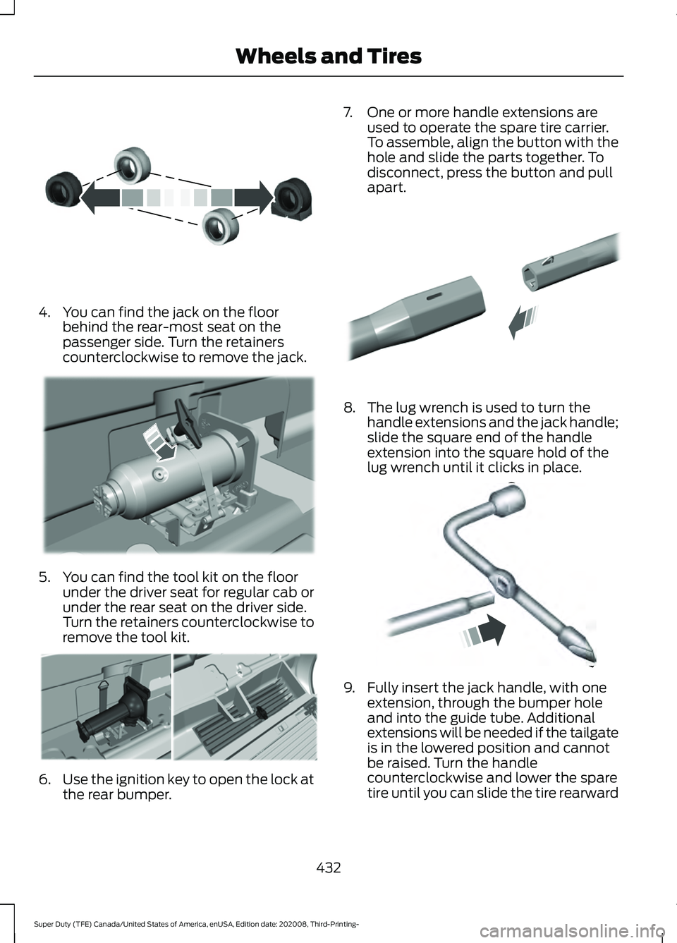
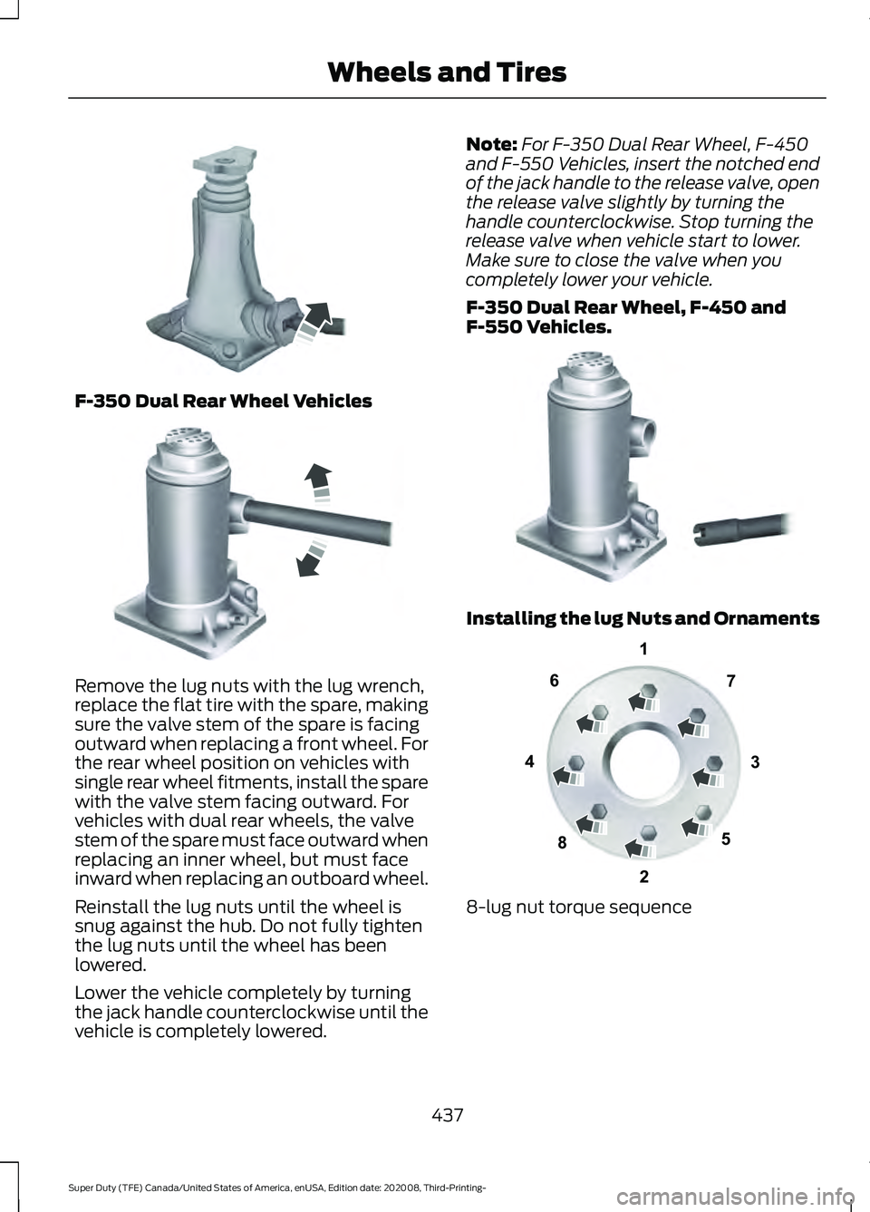
4. You can find the jack on the floor
behind the rear-most seat on the
passenger side. Turn the retainers
counterclockwise to remove the jack. 5. You can find the tool kit on the floor
under the driver seat for regular cab or
under the rear seat on the driver side.
Turn the retainers counterclockwise to
remove the tool kit. 6.
Use the ignition key to open the lock at
the rear bumper. 7. One or more handle extensions are
used to operate the spare tire carrier.
To assemble, align the button with the
hole and slide the parts together. To
disconnect, press the button and pull
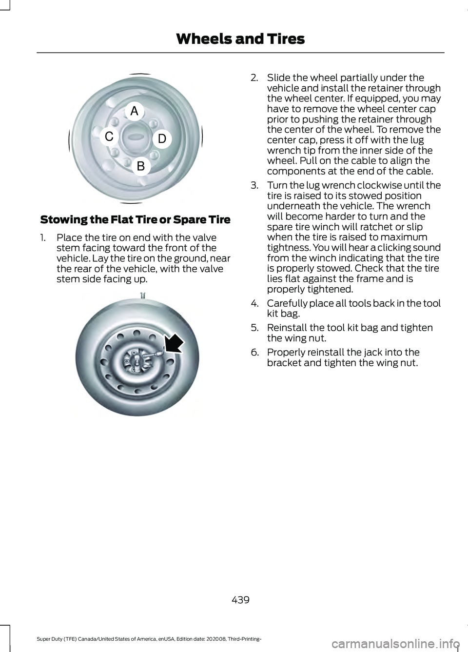
apart. 8. The lug wrench is used to turn the
handle extensions and the jack handle;
slide the square end of the handle
extension into the square hold of the
lug wrench until it clicks in place. 9. Fully insert the jack handle, with one
extension, through the bumper hole
and into the guide tube. Additional
extensions will be needed if the tailgate
is in the lowered position and cannot
be raised. Turn the handle
counterclockwise and lower the spare
tire until you can slide the tire rearward
432
Super Duty (TFE) Canada/United States of America, enUSA, Edition date: 202008, Third-Printing- Wheels and TiresE175447 E309424 E309795 E308882 E162796
Page 436 of 666

and the cable is slack. You will feel
some resistance when you turn the jack
handle assembly. If not replacing the
spare or flat tire to the underbody
storage area, raise the wheel retainer
up into the installed position.
10. Slide the retainer through the center of the spare tire wheel and remove
the spare tire. 11. Remove the wheel trim with the lug
wrench tip, or use the wheel trim tool
described later in this section.
12. Loosen each wheel lug nut one-half turn counterclockwise, but do not
remove them until the wheel is raised
off the ground. For dual rear wheel,
assemble the lug wrench and
extension tool together to access the
lug nuts. 13. Position the jack under the correct
jacking points according to following
pictures.
Removing Wheel Trim With Single
Wheels
1. Insert the flat end of the lug wrench between the wheel rim and the wheel
trim.
2. Carefully remove the wheel trim.
Vehicles With Dual Rear Alloy Wheels 433
Super Duty (TFE) Canada/United States of America, enUSA, Edition date: 202008, Third-Printing- Wheels and TiresE310417 E309794 E338541
Page 439 of 666

Front passenger side (4x4): F-350 dual
rear wheel
Front driver side (4x4): F-350 dual rear
wheel
Note:
Make sure the jack fits onto the flat
area on the outboard side of the differential
housing. Rear: F-350 dual rear wheel
Front: F-450 and F-550
Rear: F-450 and F-550
Insert the hooked end of the jack handle
into the jack and turn the jack handle
clockwise. For hydraulic jacks, operate the
handle up-and-down until the wheel is
completely off the ground and high enough
to install the spare tire.
Note:
Hydraulic jacks have a pressure relief
valve that prevents lifting loads which
exceed the jack's rated capacity.
F-250 and F-350 Single Rear Wheel
Vehicles
436
Super Duty (TFE) Canada/United States of America, enUSA, Edition date: 202008, Third-Printing- Wheels and TiresE162815 E162814 E162817 E162816 E162818
Page 440 of 666

F-350 Dual Rear Wheel Vehicles
Remove the lug nuts with the lug wrench,
replace the flat tire with the spare, making
sure the valve stem of the spare is facing
outward when replacing a front wheel. For
the rear wheel position on vehicles with
single rear wheel fitments, install the spare
with the valve stem facing outward. For
vehicles with dual rear wheels, the valve
stem of the spare must face outward when
replacing an inner wheel, but must face
inward when replacing an outboard wheel.
Reinstall the lug nuts until the wheel is
snug against the hub. Do not fully tighten
the lug nuts until the wheel has been
lowered.
Lower the vehicle completely by turning
the jack handle counterclockwise until the
vehicle is completely lowered. Note:
For F-350 Dual Rear Wheel, F-450
and F-550 Vehicles, insert the notched end
of the jack handle to the release valve, open
the release valve slightly by turning the
handle counterclockwise. Stop turning the
release valve when vehicle start to lower.
Make sure to close the valve when you
completely lower your vehicle.
F-350 Dual Rear Wheel, F-450 and
F-550 Vehicles. Installing the lug Nuts and Ornaments
8-lug nut torque sequence
437
Super Duty (TFE) Canada/United States of America, enUSA, Edition date: 202008, Third-Printing- Wheels and TiresE162811 E162819 E162812 13
4
27
6
5
8E161441
Page 442 of 666

Stowing the Flat Tire or Spare Tire
1. Place the tire on end with the valve
stem facing toward the front of the
vehicle. Lay the tire on the ground, near
the rear of the vehicle, with the valve
stem side facing up. 2. Slide the wheel partially under the
vehicle and install the retainer through
the wheel center. If equipped, you may
have to remove the wheel center cap
prior to pushing the retainer through
the center of the wheel. To remove the
center cap, press it off with the lug
wrench tip from the inner side of the
wheel. Pull on the cable to align the
components at the end of the cable.
3. Turn the lug wrench clockwise until the
tire is raised to its stowed position
underneath the vehicle. The wrench
will become harder to turn and the
spare tire winch will ratchet or slip
when the tire is raised to maximum
tightness. You will hear a clicking sound
from the winch indicating that the tire
is properly stowed. Check that the tire
lies flat against the frame and is
properly tightened.
4. Carefully place all tools back in the tool
kit bag.
5. Reinstall the tool kit bag and tighten the wing nut.
6. Properly reinstall the jack into the bracket and tighten the wing nut.
439
Super Duty (TFE) Canada/United States of America, enUSA, Edition date: 202008, Third-Printing- Wheels and TiresA
C
B
DE162824 E162800
Page 483 of 666

Note:
Some features, such as satellite
radio, may not be available in your location.
Check with an authorized dealer.
Accessing the Apps Menu Press and release the button to
access the apps menu. Follow
the on-screen prompts to make
your selection.
Accessing the Clock Settings Press and release the button to
access the clock setting.
Use the center arrow controls to
change the hours and minutes.
Accessing the Media Source Menu Press and release the button to
open the media source menu.
You can press this multiple times to
change to a SYNC-Media device or scroll
through the media sources using the arrow
buttons. Press OK to select a source.
Accessing the Phone Features Press and release the button to
access the phone features of the
SYNC system.
Accessing the Sound Settings Press and release the button to
access settings for Treble,
Midrange, Bass, Fade and
Balance.
Accessing the Settings Menu Press and release the button to
access the settings menu.
Follow the on-screen prompts
to make your selection. Adjusting the Volume
Turn to adjust the volume.
Changing Radio Stations
In radio mode, turn to search through the
radio frequency band.
In satellite radio mode, turn to find the
previous or next available satellite radio
station.
480
Super Duty (TFE) Canada/United States of America, enUSA, Edition date: 202008, Third-Printing- Audio System - Vehicles With: SYNC E265036 E265035 E280315 E142607 E265373 E265696