Page 157 of 228

the tab 14 fig. 135 of the bottle to
prevent leakage of any remaining
sealant;
adhere the speed restriction sticker
to an area where it can be viewed easily
by the driver;
pull out the air compressor hose and
the air compressor plug from the air
compressor 15 fig. 136;
install the air compressor hose 16 to
the tire valve 17 fig. 137;
insert the air compressor plug into
the accessory socket 18 fig. 138 inside
the vehicle and switch the ignition to
ACC;
turn the air compressor switch on
and inflate the tire carefully to the
correct inflation pressure;
IMPORTANT When inserting the air
compressor plug into or removing it
from the accessory socket, make sure
that the air compressor switch is off.
When turning the air compressor on/off,
use the air compressor switch.
NOTE Check the tire inflation pressure
label driver's door frame for the correct
tire inflation pressure.
NOTE Do not operate the aircompressor for a continuous
10 minutes or longer because using it
for long periods could cause a
malfunction.
NOTE If the tire inflation pressure does
not increase, repair of the tire is not
possible. If the tire does not reach the
specified tire inflation pressure within
10 minutes, it may have received
extensive damage. In this case, the
repair using the tire service kit was not
successful. Contact a Fiat Dealership.
If the tire has been over-inflated, loosen
the screw cap on the air compressor
and bleed some of the air out;
when the tire inflates to the specified
tire inflation pressure, turn the air
compressor switch off, turn the sleeve
of the air compressor hose to the left,
and pull it out of the tire valve;
install the tire valve cap;
put the tire service kit into the boot;
start driving immediately to spread
the sealant in the tire.
IMPORTANT Carefully drive the vehicle
at a speed of 80 km/h or less. If the
vehicle is driven at a speed of 80 km/h
or more, the vehicle may vibrate.
If the tire is not properly inflated, the
warning light will illuminate.
after driving the vehicle for about
10 minutes or 5 km (3 miles), connect
the air compressor to the tire and check
13608020202-36A-004
13708020202-03A-00B
13808020202-124-001
155
Page 167 of 228

SCHEDULED SERVICING PLAN
The checks listed in the Scheduled Servicing Plan, after reaching 120,000 km/8 years, must be cyclically repeated starting from
the first interval, thus following the same intervals as before.
Thousands of miles9 182736455463728190
Thousands of kilometers15 30 45 60 75 90 105 120 135 150
Years12345678910
Check tire condition/wear and adjust pressure, if
necessary. Check quick tire repair kit recharge
condition and expiry date (where provided)
●●●●●●●●●●
Check operation of lighting system (headlights,
direction indicators, hazard warning lights, boot,
passenger compartment, glove compartment,
instrumental panel warning lights, etc.)
●●●●●●●●●●
Check and, if necessary, top up fluid levels (1)●●●●●●●●●●
Check exhaust emissions/smokiness●●●●●●●●●●
Use the diagnosis socket to check engine
management system operation, emissions and,
for versions/markets where provided, engine oil
degradation
●●●●●●●●●●
Visually inspect conditions of: exterior bodywork,
underbody protection, pipes and hoses (exhaust,
fuel system, brakes), rubber elements (gaiters,
sleeves, bushes, etc.) and fasteners in sight
●●●●●
Visually inspect conditions of steering elements
and check their operation●●●●●
(1) Always only use the liquids shown in the handbook for topping up after having checked that the system is not damaged.
165
Page 168 of 228
Thousands of miles9 182736455463728190
Thousands of kilometers15 30 45 60 75 90 105 120 135 150
Years12345678910
Check endfloat of wheel bearings and front and
rear joints●●●●●
Check windscreen wiper blade position/wear●●●●●
Check operation of the wiper/washer system
and adjust jets, if necessary●●●●●
Check cleanliness of bonnet and boot locks, as
well as cleanliness and lubrication of linkages●●●●●
Check handbrake lever travel and adjust, if
necessary●●●●●●●●●●
Visually inspect conditions and wear of front/rear
disk brake pads and integrity of pad wear
indicator
●●●●●●●●●●
Visually inspect condition of evaporation control
system●●●
Visually inspect condition and tensioning of
accessory drive belt(s)●
Visually inspect conditions of toothed timing
drive belt●
Change transmission oil●
Change engine oil and replace oil filter●●●●●●●●●●
166
MAINTENANCE AND CARE
Page 189 of 228
DIMENSIONS
Dimensions are expressed in mm and refer to the vehicle equipped with its standard-supplied tyres. Height is measured with
vehicle unladen.
BOOT VOLUME: 140 litres
ABCDE F
4,055 (*) / 4,075 (**) 2,310 1,230 1,495 1,740 1,505
(*) Without license plate holder.
(**) With license plate holder.
15710000555-122-333
187
Page 223 of 228

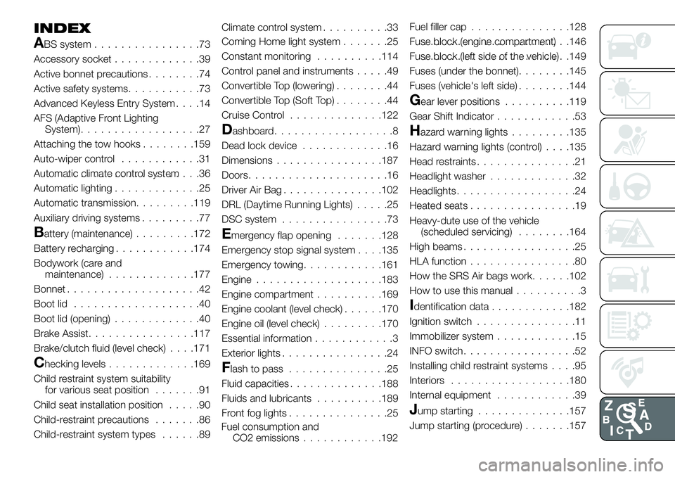
INDEX
ABS system................73
Accessory socket.............39
Active bonnet precautions........74
Active safety systems...........73
Advanced Keyless Entry System....14
AFS (Adaptive Front Lighting
System)..................27
Attaching the tow hooks........159
Auto-wiper control............31
Automatic climate control system.......................36
Automatic lighting.............25
Automatic transmission.........119
Auxiliary driving systems.........77
Battery (maintenance).........172
Battery recharging............174
Bodywork (care and
maintenance).............177
Bonnet....................42
Boot lid...................40
Boot lid (opening).............40
Brake Assist................117
Brake/clutch fluid (level check). . . .171
Checking levels.............169
Child restraint system suitability
for various seat position.......91
Child seat installation position.....90
Child-restraint precautions.......86
Child-restraint system types......89Climate control system..........33
Coming Home light system.......25
Constant monitoring..........114
Control panel and instruments.....49
Convertible Top (lowering)........44
Convertible Top (Soft Top)........44
Cruise Control..............122
Dashboard..................8
Dead lock device.............16
Dimensions................187
Doors.....................16
Driver Air Bag...............102
DRL (Daytime Running Lights).....25
DSC system................73
Emergency flap opening.......128
Emergency stop signal system. . . .135
Emergency towing............161
Engine...................183
Engine compartment..........169
Engine coolant (level check)......170
Engine oil (level check).........170
Essential information............3
Exterior lights................24
Flash to pass...............25
Fluid capacities..............188
Fluids and lubricants..........189
Front fog lights...............25Fuel filler cap...............128
Fuse block (engine compartment)......................146
Fuse block (left side of the vehicle)......................149
Fuses (under the bonnet)........145
Fuses (vehicle's left side)........144
Gear lever positions..........119
Gear Shift Indicator............53
Hazard warning lights.........135
Hazard warning lights (control). . . .135
Head restraints...............21
Headlight washer.............32
Headlights..................24
Heated seats................19
Heavy-dute use of the vehicle
(scheduled servicing)........164
High beams.................25
HLA function................80
How the SRS Air bags work......102
How to use this manual..........3
Identification data............182
Ignition switch...............11
Immobilizer system............15
INFO switch.................52
Installing child restraint systems....95
Interiors..................180
Internal equipment............39
Jump starting..............157
Jump starting (procedure).......157
Fuel consumption and
CO2 emissions............192
Page:
< prev 1-8 9-16 17-24