Page 233 of 328

IN CASE OF EMERGENCY231
(Continued)
6. Remove the jack and lug wrench assembly
from under the spare tire. Turn the jack screw
to the left to loosen the lug wrench, and
remove the wrench from the jack assembly.
JACKING AND CHANGING A TIRE
Jack Warning Label
Placement for the front and rear jacking locations
are critical. See the following images for proper
jacking locations.
Jack Engagement Locations
WARNING!
A loose tire or jack thrown forward in a collision or
hard stop could endanger the occupants of the
vehicle. Always stow the jack parts and the spare
tire in the places provided. Have the deflated (flat)
tire repaired or replaced immediately.
WARNING!
Carefully follow these tire changing warnings to
help prevent personal injury or damage to your
vehicle:
Always park on a firm, level surface as far from
the edge of the roadway as possible before
raising the vehicle.
Turn on the Hazard Warning Flashers.
Apply the parking brake firmly and place an
automatic transmission in PARK; a manual
transmission in REVERSE or FIRST gear.
Block the wheel diagonally opposite the wheel
to be raised.
Never start or run the engine with the vehicle
on a jack.
Do not let anyone sit in the vehicle when it is
on a jack.
Do not get under the vehicle when it is on a
jack. If you need to get under a raised vehicle,
take it to a service center where it can be
raised on a lift.
Only use the jack in the positions indicated
and for lifting this vehicle during a tire change.
If working on or near a roadway, be extremely
careful of motor traffic.
WARNING!
CAUTION!
Do not attempt to raise the vehicle by jacking on
locations other than those indicated in the
Jacking Instructions for this vehicle.7
21_LA_OM_EN_USC_t.book Page 231
Page 234 of 328

232IN CASE OF EMERGENCY
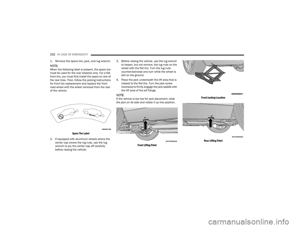
1. Remove the spare tire, jack, and lug wrench.
NOTE:When the following label is present, the spare tire
must be used for the rear wheel(s) only. For a flat
front tire, you must first install the spare on one of
the rear tires. Then, follow the jacking instructions
for front tire replacement and replace the front
road wheel with the wheel removed from the rear
of the vehicle.
Spare Tire Label
2. If equipped with aluminum wheels where the center cap covers the lug nuts, use the lug
wrench to pry the center cap off carefully
before raising the vehicle. 3. Before raising the vehicle, use the lug wrench
to loosen, but not remove, the lug nuts on the
wheel with the flat tire. Turn the lug nuts
counterclockwise one turn while the wheel is
still on the ground.
4. Place the jack underneath the lift area that is closest to the flat tire. Turn the jack screw
clockwise to firmly engage the jack saddle with
the lift area of the sill flange.
NOTE:If the vehicle is too low for jack placement, slide
the jack on its side and rotate it up into position.
Front Lifting Point Front Jacking Location
Rear Lifting Point
21_LA_OM_EN_USC_t.book Page 232
Page 235 of 328

IN CASE OF EMERGENCY233
Rear Jacking Location
5. Raise the vehicle just enough to remove the flat tire and install the spare tire.
6. Remove the lug nuts and tire.
7. Mount the spare tire.
Mounting Spare Tire
NOTE:For vehicles so equipped, do not attempt to install
a center cap or wheel cover on the compact spare
Ú
page 292.
8. Install the lug nuts with the cone shaped end of the lug nut toward the wheel. Lightly tighten
the lug nuts. 9. Lower the vehicle to the ground by turning the
jack handle counterclockwise.
10. Finish tightening the wheel bolts. Push down on the wrench while at the end of the handle
for increased leverage. Tighten the wheel bolts
in a star pattern until each wheel bolt has been
tightened twice Úpage 301. If in doubt about
the correct tightness, have them checked with
a torque wrench by an authorized dealer or at
a service station.
11. Stow the jack, tools and flat tire. Make sure the base of the jack faces the front of the vehicle
before tightening down the fastener.
WARNING!
Raising the vehicle higher than necessary can
make the vehicle less stable. It could slip off the
jack and hurt someone near it. Raise the vehicle
only enough to remove the tire.
CAUTION!
Be sure to mount the spare tire with the valve
stem facing outward. The vehicle could be
damaged if the spare tire is mounted incorrectly.
WARNING!
To avoid the risk of forcing the vehicle off the
jack, do not tighten the wheel nuts fully until the
vehicle has been lowered. Failure to follow this
warning may result in serious injury.
WARNING!
A loose tire or jack thrown forward in a collision
or hard stop could endanger the occupants of
the vehicle. Always stow the jack parts and the
spare tire in the places provided. Have the
deflated (flat) tire repaired or replaced
immediately.
7
21_LA_OM_EN_USC_t.book Page 233
Page 274 of 328

272SERVICING AND MAINTENANCE
Rear Interior Fuses
There is also a power distribution center located in
the trunk under the spare tire access panel. This
center contains fuses and relays. Fuse cavity
location and descriptions are printed on the inside
of the power distribution center cover.
Rear Power Distribution Center
CAUTION!
When installing the power distribution center
cover, it is important to ensure the cover is
properly positioned and fully latched. Failure
to do so may allow water to get into the power
distribution center and possibly result in an
electrical system failure.
When replacing a blown fuse, it is important to
use only a fuse having the correct amperage
rating. The use of a fuse with a rating other
than indicated may result in a dangerous elec-
trical system overload. If a properly rated fuse
continues to blow, it indicates a problem in the
circuit that must be corrected.
Cavity Cartridge Fuse Mini-FuseDescription
* If Equipped
F02 60 Amp Yellow –Front PDC Feed #1
F03 ––Spare
F04 60 Amp Yellow –Front PDC Feed #2
F05 30 Amp Pink
–Sunroof
20 Amp Blue – Police Dome Lamp – Police
F06 40 Amp Green –Exterior Lighting #1
F07 40 Amp Green –Exterior Lighting #2
F08 30 Amp Pink –Interior Lighting
21_LA_OM_EN_USC_t.book Page 272
Page 275 of 328
SERVICING AND MAINTENANCE273
F09 40 Amp Green –Power Locks
F10 30 Amp Pink –Driver Door Control Module
F11 30 Amp Pink –Passenger Door Control Module
F12 –20 Amp YellowCigar Lighter/IP APO/RR USB
(Selectable Fuse) *
F15 40 Amp Green –HVAC Blower
F16 20 Amp Blue –Left Spot Lamp – Police
F17 20 Amp Blue –Right Spot Lamp – Police
F18 30 Amp Pink –VISM MOD (Police)
F19 ––Spare
F20 ––Spare
F21 30 Amp Pink –Fuel Pump (Non 6.2L ADR)
F22 –5 Amp TanCyber Gateway Mod
F23 –10 Amp RedFuel Door */Diagnostic Port
F24 –10 Amp RedIntegrated Center Stack
F25 –10 Amp RedTire Pressure Monitor
F26 –15 Amp BlueTrans Mod (Charger Non- Police/300)
F27 –25 Amp ClearAmplifier *
F31 –25 Amp BreakerPower Seats *
F32 –15 Amp BlueHVAC Module/Cluster
Cavity Cartridge Fuse Mini-FuseDescription
* If Equipped
8
21_LA_OM_EN_USC_t.book Page 273
Page 282 of 328

280SERVICING AND MAINTENANCE
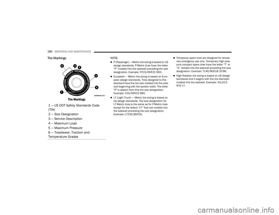
Tire Markings
Tire Markings
NOTE:
P (Passenger) — Metric tire sizing is based on US
design standards. P-Metric tires have the letter
“P” molded into the sidewall preceding the size
designation. Example: P215/65R15 95H.
European — Metric tire sizing is based on Euro -
pean design standards. Tires designed to this
standard have the tire size molded into the side -
wall beginning with the section width. The letter
"P" is absent from this tire size designation.
Example: 215/65R15 96H.
LT (Light Truck) — Metric tire sizing is based on
US design standards. The size designation for
LT-Metric tires is the same as for P-Metric tires
except for the letters “LT” that are molded into
the sidewall preceding the size designation.
Example: LT235/85R16.
Temporary spare tires are designed for tempo -
rary emergency use only. Temporary high pres -
sure compact spare tires have the letter “T” or
“S” molded into the sidewall preceding the size
designation. Example: T145/80D18 103M.
High flotation tire sizing is based on US design
standards and it begins with the tire diameter
molded into the sidewall. Example: 31x10.5
R15 LT.
1 — US DOT Safety Standards Code
(TIN)
2 — Size Designation
3 — Service Description
4 — Maximum Load
5 — Maximum Pressure
6 — Treadwear, Traction and
Temperature Grades
21_LA_OM_EN_USC_t.book Page 280
Page 283 of 328
SERVICING AND MAINTENANCE281
TIRE SIZING CHART
EXAMPLE:
Example Size Designation: P215/65R15XL 95H, 215/65R15 96H, LT235/85R16C, T145/80D18 103M, 31x10.5 R15 LT
P = Passenger car tire size based on US design standards, or
"....blank...." = Passenger car tire based on European design standards, or
LT = Light truck tire based on US design standards, or
T or S = Temporary spare tire or
31 = Overall diameter in inches (in)
215, 235, 145 = Section width in millimeters (mm)
65, 85, 80 = Aspect ratio in percent (%)
Ratio of section height to section width of tire, or
10.5 = Section width in inches (in)
R = Construction code
"R" means radial construction, or
"D" means diagonal or bias construction
15, 16, 18 = Rim diameter in inches (in)
8
21_LA_OM_EN_USC_t.book Page 281
Page 287 of 328

SERVICING AND MAINTENANCE285
Tire Loading And Tire Pressure
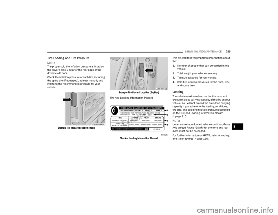
NOTE:The proper cold tire inflation pressure is listed on
the driver’s side B-pillar or the rear edge of the
driver's side door.
Check the inflation pressure of each tire, including
the spare tire (if equipped), at least monthly and
inflate to the recommended pressure for your
vehicle.
Example Tire Placard Location (Door) Example Tire Placard Location (B-pillar)
Tire And Loading Information Placard
Tire And Loading Information Placard
This placard tells you important information about
the:
1. Number of people that can be carried in the
vehicle.
2. Total weight your vehicle can carry.
3. Tire size designed for your vehicle.
4. Cold tire inflation pressures for the front, rear, and spare tires.
Loading
The vehicle maximum load on the tire must not
exceed the load carrying capacity of the tire on your
vehicle. You will not exceed the tire's load carrying
capacity if you adhere to the loading conditions,
tire size, and cold tire inflation pressures specified
on the Tire and Loading Information placard
Úpage 110.
NOTE:Under a maximum loaded vehicle condition, Gross
Axle Weight Rating (GAWR) for the front and rear
axles must not be exceeded.
For further information on GAWR, vehicle loading,
and trailer towing Ú page 110.8
21_LA_OM_EN_USC_t.book Page 285