2021 CHRYSLER VOYAGER instrument panel
[x] Cancel search: instrument panelPage 73 of 348

GETTING TO KNOW YOUR VEHICLE71
INTERIOR STORAGE AND EQUIPMENT
STORAGE
Glove Compartment
The glove compartment is located on the
passenger side of the instrument panel.
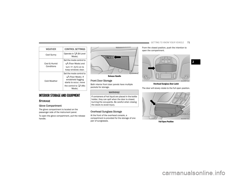
To open the glove compartment, pull the release
handle.
Release Handle
Front Door Storage
Both interior front door panels have multiple
pockets for storage.
Overhead Sunglass Storage
At the front of the overhead console, a
compartment is provided for the storage of one
pair of sunglasses.From the closed position, push the intention to
open the compartment.
Overhead Sunglass Door Latch
The door will slowly rotate to the full open position.
Full Open Position
Cool Sunny
Operate in (Bi-Level
Mode).
Cool & Humid Conditions Set the mode control to
(Floor Mode) and
turn (A/C) on to
keep windows clear.
Cold Weather Set the mode control to
(Floor Mode). If
windshield fogging
starts to occur, move
the control to (Mix Mode).
WEATHER CONTROL SETTINGS
WARNING!
If containers of hot liquid are placed in the bottle
holder, they can spill when the door is closed,
burning the occupants. Be careful when closing
the doors to avoid injury.
2
21_RUV_OM_EN_USC_t.book Page 71
Page 74 of 348

72GETTING TO KNOW YOUR VEHICLE
Instrument Panel Drawer
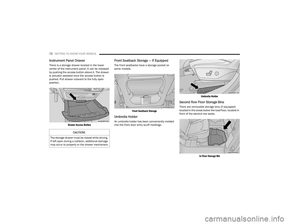
There is a storage drawer located in the lower
center of the instrument panel. It can be released
by pushing the access button above it. The drawer
is actuator assisted once the access button is
pushed. Pull drawer outward to the fully open
position.
Drawer Access Button
Front Seatback Storage — If Equipped
The front seatbacks have a storage pocket on
some models.
Front Seatback Storage
Umbrella Holder
An umbrella holder has been conveniently molded
into the front door entry scuff moldings.
Umbrella Holder
Second Row Floor Storage Bins
There are removable storage bins (if equipped)
located in the areas below the load floor, located in
front of the second row seats.
In Floor Storage Bin
CAUTION!
The storage drawer must be closed while driving.
If left open during a collision, additional damage
may occur to property or the drawer mechanism.
21_RUV_OM_EN_USC_t.book Page 72
Page 78 of 348

76GETTING TO KNOW YOUR VEHICLE
USB Charging Port In The Floor Tray
NOTE:The USB outlet in the bottom of the instrument
panel can be switched from ignition only to
constant battery powered all the time. See an
authorized dealer for details.
Rear Seat USB Charging Port 3rd Row USB Charging Port
NOTE:The USB “Charge Only” ports will recharge battery
operated USB devices when connected.
Different scenarios are listed below when a
non-phone device is plugged into the smaller and
larger USB ports, and when a phone device is
plugged into the smaller and larger USB ports:
“A new device is now connected. Previous
connection was lost”.
“(Phone Name) now connected. Previous
connection was lost”.
“Another device is in use through the same USB
port. Please disconnect the first device to use
the second device”.
Plugging in a phone or another USB device may
cause the connection to a previous device to be
lost.
POWER OUTLETS
Your vehicle is equipped with 12 Volt (15 Amp)
power outlets, and 5 Volt (2.5 Amp) USB ports, that
can be used to power cellular phones, small
electronics and other low powered electrical
accessories. The power outlets can be labeled with
either a “key” or a “battery” symbol to indicate how
the outlet is powered. Power outlets labeled with a
“key” are powered when the ignition is in the ON or
ACC position, while the outlets labeled with a
“battery” are connected directly to the battery and
powered at all times.
NOTE:All accessories connected to the “battery” powered
outlets should be removed or turned off when the
vehicle is not in use to protect the battery against
discharge.
CAUTION!
Power outlets are designed for accessory plugs
only. Do not insert any other object in the power
outlets as this will damage the outlet and blow
the fuse. Improper use of the power outlet can
cause damage not covered by your New Vehicle
Limited Warranty.
21_RUV_OM_EN_USC_t.book Page 76
Page 79 of 348

GETTING TO KNOW YOUR VEHICLE77
The front power outlet is located at the bottom of
the instrument panel.
12 Volt Front Power Outlet
In addition to the front power outlets, there is also
a power outlet located in the rear cargo area.
The rear power outlet is located in the right rear
cargo area.
Rear Power Outlet Power Outlet Fuse Locations
1 — F95A (Ignition)/F95B (Battery) I/P Power
Outlet 10A (If Equipped)
2 — F85 Cigar Lighter 20A
3 — F60 RR Cargo Power Outlet 20A
WARNING!
To avoid serious injury or death:
Only devices designed for use in this type of
outlet should be inserted into any 12 Volt
outlet.
Do not touch with wet hands.
Close the lid when not in use and while driving
the vehicle.
If this outlet is mishandled, it may cause an
electric shock and failure.
CAUTION!
Many accessories that can be plugged in draw
power from the vehicle's battery, even when
not in use (i.e., cellular phones, etc.). Eventu
-
ally, if plugged in long enough, the vehicle's
battery will discharge sufficiently to degrade
battery life and/or prevent the engine from
starting.
Accessories that draw higher power (i.e.,
coolers, vacuum cleaners, lights, etc.) will
degrade the battery even more quickly. Only
use these intermittently and with greater
caution.
After the use of high power draw accessories,
or long periods of the vehicle not being started
(with accessories still plugged in), the vehicle
must be driven a sufficient length of time to
allow the generator to recharge the vehicle's
battery.
2
21_RUV_OM_EN_USC_t.book Page 77
Page 80 of 348

78GETTING TO KNOW YOUR VEHICLE
CIGAR LIGHTER — IF EQUIPPED
NOTE:Cigar lighters can be purchased at an authorized
dealer through Mopar® parts.
The cigar lighter is located at the bottom of the
instrument panel. Push lighter inward to heat.
After a few seconds, the lighter automatically
returns to its initial position and is ready to be
used.
SMOKER'S PACKAGE KIT — IF EQUIPPED
With the optional authorized dealer-installed
Smoker's Package Kit, a removable ash receiver is
inserted into one of the two cupholders in the
center floor console. To install the ash receiver,
align the receiver so the thumb grip on the lid is
facing rearward. Push the ash receiver into either
of the cup wells to secure. Pull upward on the ash
receiver to remove for cleaning and/or storage.
The left rear trim panel cupholder is designed to
accommodate a second ash receiver, if desired.
WINDOWS
POWER WINDOWS
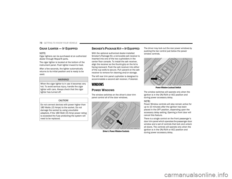
The window switches on the driver’s door trim
panel control all of the door windows.
Driver’s Power Window Controls
The driver may lock out the rear power windows by
pushing the bar control just below the power
window controls.
Power Window Lockout Switch
The window switches will operate only when the
ignition is in the ON/RUN or ACC position and
during power accessory delay.
NOTE:Power Window controls will also remain active for
up to 10 minutes after the ignition has been
placed in the OFF position, depending upon the
accessory delay setting. Opening a front door will
cancel this feature.
There is a single control on the front passenger’s
door trim panel which operates the passenger door
window and a set of controls that lock and unlock
all doors. The controls will operate only when the
ignition is in the ON/RUN or ACC position and
during power accessory delay.
WARNING!
When the cigar lighter is in use it becomes very
hot. To avoid serious injury, handle the cigar
lighter with care. Always check that the cigar
lighter has turned off.
CAUTION!
Do not connect devices with power higher than
180 Watts (15 Amps) to the socket. Do not
damage the socket by using unsuitable
adaptors. If the 180 Watt (15 Amp) power rating
is exceeded the fuse protecting the system will
need to be replaced.
21_RUV_OM_EN_USC_t.book Page 78
Page 82 of 348

80GETTING TO KNOW YOUR VEHICLE
WIND BUFFETING
Wind buffeting can be described as the perception
of pressure on the ears or a helicopter-type sound
in the ears. Your vehicle may exhibit wind buffeting
with the windows down, or the sunroof (if
equipped) in certain open or partially open
positions. This is a normal occurrence and can be
minimized. If the rear windows are open and
buffeting occurs, open the front and rear windows
together to minimize the buffeting. If the buffeting
occurs with the sunroof open, adjust the sunroof
opening to minimize the buffeting.
HOOD
OPENING
The hood release lever (to open the primary latch)
and safety latch (to open the secondary latch)
must be released to open the hood.
1. Pull the hood release lever located under the
driver’s side of the instrument panel.
Hood Release Lever
2. Move to the outside of the front of the vehicle.
3. Push the safety latch release lever toward the passenger side of the vehicle. The safety latch
is located behind the center front edge of the
hood.
Safety Latch Release Lever Location
4. Remove the support rod from the locking tab
and insert it into the seat located on the
underside of the hood.
NOTE:
Before lifting the hood, check that the wiper
arms are not in motion and not in the lifted posi -
tion.
While lifting the hood, use both hands.
Vehicle must be at a stop and the transmission
must be in PARK.
CLOSING
1. Hold up the hood with one hand and with the other hand remove the support rod from its
seat and reinsert it into the locking tab.
2. Lower the hood to approximately 12 inches (30 cm) from the engine compartment and
drop it. Make sure that the hood is completely
closed.
WARNING!
Be sure the hood is fully latched before driving
your vehicle. If the hood is not fully latched, it
could open when the vehicle is in motion and
block your vision. Failure to follow this warning
could result in serious injury or death.
21_RUV_OM_EN_USC_t.book Page 80
Page 89 of 348

87
GETTING TO KNOW YOUR INSTRUMENT PANEL
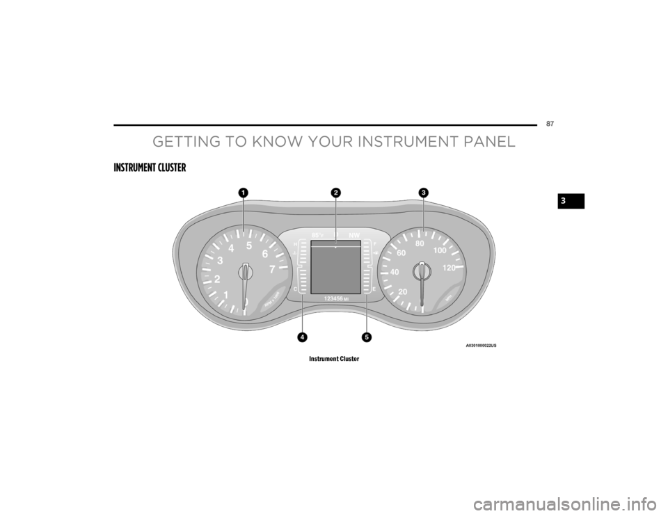
INSTRUMENT CLUSTER
Instrument Cluster
3
21_RUV_OM_EN_USC_t.book Page 87
Page 90 of 348

88GETTING TO KNOW YOUR INSTRUMENT PANEL
INSTRUMENT CLUSTER DESCRIPTIONS
1. Tachometer
Indicates the engine speed in revolutions
per minute (RPM x 1000).
2. Instrument Cluster Display
When the appropriate conditions exist, this
display shows the instrument cluster
display messages
Úpage 89.
3. Speedometer
Indicates vehicle speed.
4. Temperature Gauge
The temperature gauge shows engine
coolant temperature. Any reading within the
normal range indicates that the engine
cooling system is operating satisfactorily.
The gauge can indicate a higher tempera -
ture when driving in hot weather or up
mountain grades. It should not be allowed
to exceed the upper limits of the normal
operating range. 5. Fuel Gauge
The gauge shows the level of fuel in the
fuel tank when the ignition switch is in the
ON/RUN position.
The fuel pump symbol points to
the side of the vehicle where the
fuel door is located.
NOTE:The hard telltales will illuminate for a bulb check
when the ignition is first cycled.
INSTRUMENT CLUSTER DISPLAY
Your vehicle is equipped with an instrument cluster
display, which offers useful information to the
driver. With the ignition in the OFF position (and the
key removed, for vehicles with mechanical key),
opening/closing of a door will activate the display
for viewing, and display the total miles or
kilometers in the odometer. Your instrument
cluster display is designed to display important
information about your vehicle’s systems and
features. Using a driver interactive display located
on the instrument panel, your instrument cluster
display can show you how systems are working and
give you warnings when they are not. The steering
wheel mounted controls allow you to scroll through
and enter the main menus and submenus. You can
access the specific information you want and
make selections and adjustments.
WARNING!
Driving with a hot engine cooling system could
damage your vehicle. If the temperature gauge
reaches “H” pull over and stop the vehicle. Idle
the vehicle with the air conditioner turned off
until the gauge drops back into the normal range
and is no longer red. If the gauge remains on the
“H”, turn the engine off immediately and call an
authorized dealer for service.
WARNING!
A hot engine cooling system is dangerous. You or
others could be badly burned by steam or boiling
coolant. You may want to call an authorized
dealer for service if your vehicle overheats
Úpage 286.
21_RUV_OM_EN_USC_t.book Page 88