2021 CHRYSLER VOYAGER change time
[x] Cancel search: change timePage 95 of 348

GETTING TO KNOW YOUR INSTRUMENT PANEL93
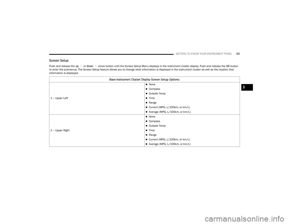
Screen Setup
Push and release the up or down arrow button until the Screen Setup Menu displays in the instrument cluster display. Push and release the OK button
to enter the submenus. The Screen Setup feature allows you to change what information is displayed in the instrument cluster as well as the location that
information is displayed.
Base Instrument Cluster Display Screen Setup Options:
1 — Upper Left
None
Compass
Outside Temp
Time
Range
Current (MPG, L/100km, or km/L)
Average (MPG, L/100km, or km/L)
2 — Upper Right
None
Compass
Outside Temp
Time
Range
Current (MPG, L/100km, or km/L)
Average (MPG, L/100km, or km/L)
3
21_RUV_OM_EN_USC_t.book Page 93
Page 97 of 348

GETTING TO KNOW YOUR INSTRUMENT PANEL95
Speed Warning — If Equipped
Push and release the up or down arrow
button until Speed Warning is highlighted in the
instrument cluster display. Push and release the
OK button to enter Speed Warning. Use the
up or down arrow button to turn the Speed
Warning ON or OFF, then push and release the OK
button to confirm the selection. If the ON status is
selected, use the up or down arrow button
to set the desired speed, then push the OK button
to set the speed for the Speed Warning. A Speed
Warning telltale will illuminate in the instrument
cluster, with a number matching the set speed,
with a pop-up message to inform the driver that the
Speed Warning has been set to the desired speed.
Each time the set speed is exceeded, a single
chime will sound and a pop-up warning message
will display. If the set speed is exceeded more than
2 mph (3 km/h), a continuous chime will sound for
up to 10 seconds, or until the speed is no longer
exceeded. The telltale in the instrument cluster will
also change from white to yellow, and a pop-up
warning message will pop-up on the instrument
cluster display.
NOTE:Speed Warning is unavailable while KeySense is in
use.
BATTERY SAVER ON/BATTERY SAVER
M
ODE MESSAGE — ELECTRICAL LOAD
R
EDUCTION ACTIONS — IF EQUIPPED
This vehicle is equipped with an Intelligent Battery
Sensor (IBS) to perform additional monitoring of
the electrical system and status of the vehicle
battery.
In cases when the IBS detects charging system
failure, or the 12 Volt vehicle battery conditions are
deteriorating, electrical load reduction actions will
take place to extend the driving time and distance
of the vehicle. This is done by reducing power to or
turning off non-essential 12 Volt electrical loads.
Load reduction will be functional when the vehicle
propulsion system is active.
The vehicle may not be running depending on the
High Voltage (HV) battery State Of Charge (SOC) or
temperature. It will display a message if there is a
risk of battery depletion to the point where the
vehicle may stall due to lack of electrical supply, or
will not restart after the current drive cycle.
When 12 Volt load reduction is activated, the
message “Battery Saver On” or “Battery Saver
Mode” will appear in the instrument cluster
display. These messages indicate the vehicle battery has a
low state of charge and continues to lose electrical
charge at a rate that the charging system cannot
sustain.NOTE:
The charging system is independent from load
reduction. The charging system performs a diag
-
nostic on the charging system continuously.
If the Battery Charge Warning Light is on it may
indicate a problem with the charging system
Úpage 98.
The electrical loads that may be switched off
(if equipped), and vehicle functions which can be
effected by load reduction:
Heated Seat/Vented Seats/Heated Wheel
Heated/Cooled Cup Holders — If Equipped
Rear Defroster And Heated Mirrors
HVAC System
115 Volts AC Power Inverter System
Audio and Telematics System
3
21_RUV_OM_EN_USC_t.book Page 95
Page 108 of 348

106 (Continued)
STARTING AND OPERATING
STARTING THE ENGINE
Before starting your vehicle, adjust your seat,
adjust both inside and outside mirrors, and fasten
your seat belts. Start the engine with the gear selector in the
NEUTRAL (N) or PARK (P) position. Apply the brake
before shifting to any driving range.
NORMAL STARTING
To Turn On The Engine Using ENGINE START/STOP
Button
1. The transmission must be in PARK or NEUTRAL.
2. Press and hold the brake pedal while pushing the ENGINE START/STOP button once.
3. The system starts the vehicle. If the vehicle fails to start, the starter will disengage
automatically after 10 seconds.
4. If you wish to stop the cranking of the engine prior to the engine starting, push the button
again. ENGINE START/STOP Button Functions — With
Driver’s Foot OFF The Brake Pedal (In PARK Or
NEUTRAL Position)
The ENGINE START/STOP button operates similar
to an ignition switch. It has three positions; OFF,
ACC, and RUN. To change the ignition positions
without starting the vehicle and to use the
accessories follow these steps:
Start with the ignition in the OFF position.
Push the ENGINE START/STOP button once to
place the ignition to the ACC position (instru
-
ment cluster will display “ACC”).
Push the ENGINE START/STOP button a second
time to place the ignition to the RUN position
(instrument cluster will display “ON/RUN”).
Push the ENGINE START/STOP button a third
time to return the ignition to the OFF position
(instrument cluster will display “OFF”).
NOTE:Only press one pedal at a time while driving the
vehicle. Torque performance of the vehicle could
be reduced if both pedals are pressed at the same
time. If pressure is detected on both pedals simul -
taneously, a warning message will display in the
instrument cluster
Úpage 89.
WARNING!
When exiting the vehicle, always remove the
key fob from the vehicle and lock your vehicle.
Never leave children alone in a vehicle, or with
access to an unlocked vehicle.
Allowing children to be in a vehicle unattended
is dangerous for a number of reasons. A child
or others could be seriously or fatally injured.
Children should be warned not to touch the
parking brake, brake pedal or the transmis -
sion gear selector.
Do not leave the key fob in or near the vehicle,
or in a location accessible to children, and do
not leave the ignition of a vehicle equipped
with Keyless Enter ‘n Go™ in the ACC or ON/
RUN mode. A child could operate power
windows, other controls, or move the vehicle.
Do not leave children or animals inside parked
vehicles in hot weather. Interior heat build-up
may cause serious injury or death.
WARNING!
21_RUV_OM_EN_USC_t.book Page 106
Page 132 of 348

130STARTING AND OPERATING
Payload
The payload of a vehicle is defined as the allowable
load weight a truck can carry, including the weight
of the driver, all passengers, options and cargo.
Gross Axle Weight Rating (GAWR)
The GAWR is the maximum permissible load on the
front and rear axles. The load must be distributed
in the cargo area so that the GAWR of each axle is
not exceeded.
Each axle GAWR is determined by the components
in the system with the lowest load carrying capacity
(axle, springs, tires or wheels). Heavier axles or
suspension components sometimes specified by
purchasers for increased durability does not
necessarily increase the vehicle's GVWR.
Tire Size
The tire size on the Vehicle Certification Label
represents the actual tire size on your vehicle.
Replacement tires must be equal to the load
capacity of this tire size.
Rim Size
This is the rim size that is appropriate for the tire
size listed.
Inflation Pressure
This is the cold tire inflation pressure for your
vehicle for all loading conditions up to full GAWR.
Curb Weight
The curb weight of a vehicle is defined as the total
weight of the vehicle with all fluids, including
vehicle fuel, at full capacity conditions, and with no
occupants or cargo loaded into the vehicle. The
front and rear curb weight values are determined
by weighing your vehicle on a commercial scale
before any occupants or cargo are added.
Loading
The actual total weight and the weight of the front
and rear of your vehicle at the ground can best be
determined by weighing it when it is loaded and
ready for operation.
The entire vehicle should first be weighed on a
commercial scale to ensure that the GVWR has not
been exceeded. The weight on the front and rear of
the vehicle should then be determined separately
to be sure that the load is properly distributed over
the front and rear axle. Weighing the vehicle may
show that the GAWR of either the front or rear axles
has been exceeded but the total load is within the
specified GVWR. If so, weight must be shifted from
front to rear or rear to front as appropriate until the
specified weight limitations are met. Store the
heavier items down low and be sure that the
weight is distributed equally. Stow all loose items
securely before driving. Improper weight distributions can have an adverse
effect on the way your vehicle steers and handles
and the way the brakes operate.
TRAILER TOWING
In this section you will find safety tips and
information on limits to the type of towing you can
reasonably do with your vehicle. Before towing a
trailer, carefully review this information to tow your
load as efficiently and safely as possible.
To maintain the New Vehicle Limited Warranty
coverage, follow the requirements and
recommendations in this manual concerning
vehicles used for trailer towing.
COMMON TOWING DEFINITIONS
The following trailer towing related definitions will
assist you in understanding the following
information:
CAUTION!
Do not load your vehicle any heavier than the
GVWR or the maximum front and rear GAWR. If
you do, parts on your vehicle can break, or it can
change the way your vehicle handles. This could
cause you to lose control. Also overloading can
shorten the life of your vehicle.
21_RUV_OM_EN_USC_t.book Page 130
Page 144 of 348

142MULTIMEDIA
UCONNECT SETTINGS
The Uconnect system uses a combination of
buttons on the touchscreen and buttons on the
faceplate located on the center of the instrument
panel. These buttons allow you to access and
change the Customer Programmable Features.
Many features can vary by vehicle.
Buttons on the faceplate are located below and/or
beside the Uconnect system in the center of the
instrument panel. In addition, there is a Scroll/
Enter control knob located on the right side. Turn
the control knob to scroll through menus and
change settings. Push the center of the control
knob one or more times to select or change a
setting.
Your Uconnect system may also have Screen Off
and Mute buttons on the faceplate.
Push the Screen Off button on the faceplate to turn
off the Uconnect screen. Push the button again or
tap the screen to turn the screen on.
Press the Back Arrow button to exit out of a Menu
or certain option on the Uconnect system.
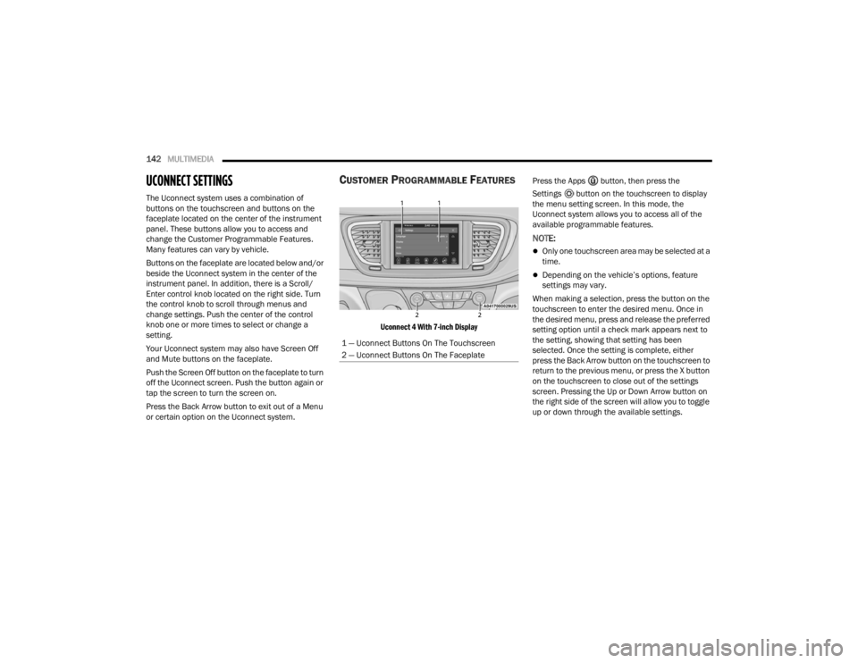
CUSTOMER PROGRAMMABLE FEATURES
Uconnect 4 With 7-inch Display
Press the Apps button, then press the
Settings button on the touchscreen to display
the menu setting screen. In this mode, the
Uconnect system allows you to access all of the
available programmable features.
NOTE:
Only one touchscreen area may be selected at a
time.
Depending on the vehicle’s options, feature
settings may vary.
When making a selection, press the button on the
touchscreen to enter the desired menu. Once in
the desired menu, press and release the preferred
setting option until a check mark appears next to
the setting, showing that setting has been
selected. Once the setting is complete, either
press the Back Arrow button on the touchscreen to
return to the previous menu, or press the X button
on the touchscreen to close out of the settings
screen. Pressing the Up or Down Arrow button on
the right side of the screen will allow you to toggle
up or down through the available settings.
1 — Uconnect Buttons On The Touchscreen
2 — Uconnect Buttons On The Faceplate
21_RUV_OM_EN_USC_t.book Page 142
Page 145 of 348

MULTIMEDIA143
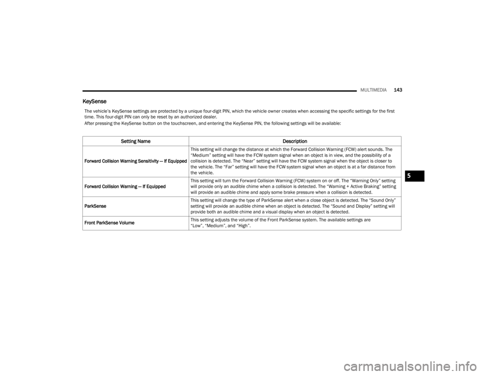
KeySense
The vehicle’s KeySense settings are protected by a unique four-digit PIN, which the vehicle owner creates when accessing the specific settings for the first
time. This four-digit PIN can only be reset by an authorized dealer.
After pressing the KeySense button on the touchscreen, and entering the KeySense PIN, the following settings will be available:
Setting Name Description
Forward Collision Warning Sensitivity — If EquippedThis setting will change the distance at which the Forward Collision Warning (FCW) alert sounds. The
“Medium” setting will have the FCW system signal when an object is in view, and the possibility of a
collision is detected. The “Near” setting will have the FCW system signal when the object is closer to
the vehicle. The “Far” setting will have the FCW system signal when an object is at a far distance from
the vehicle.
Forward Collision Warning — If Equipped This setting will turn the Forward Collision Warning (FCW) system on or off. The “Warning Only” setting
will provide only an audible chime when a collision is detected. The “Warning + Active Braking” setting
will provide an audible chime and apply some brake pressure when a collision is detected.
ParkSense This setting will change the type of ParkSense alert when a close object is detected. The “Sound Only”
setting will provide an audible chime when an object is detected. The “Sound and Display” setting will
provide both an audible chime and a visual display when an object is detected.
Front ParkSense Volume This setting adjusts the volume of the Front ParkSense system. The available settings are
“Low”, “Medium”, and “High”.
5
21_RUV_OM_EN_USC_t.book Page 143
Page 146 of 348

144MULTIMEDIA
Language
Rear ParkSense Volume This setting adjusts the volume of the Rear ParkSense system. The available settings are
“Low”, “Medium”, and “High”.
Rear ParkSense Braking Assist This setting will turn the Rear ParkSense Braking Assist on or off.
Blind Spot Alert — If Equipped This setting will change the type of alert provided when an object is detected in a vehicle’s blind spot.
The “Lights” setting will activate the Blind Spot Alert lights on the outside mirrors. The “Lights & Chime”
setting will activate both the lights on the outside mirrors and an audible chime.
Maximum Vehicle Speed This setting will adjust the Maximum Vehicle Speed. This feature can be set to 65, 70, 75, 80, or
85 mph (90, 95, 100, 105 or 110 km/h) by using the “-” and “+” options.
Start Up Fuel Level Message This setting will turn the Start Up Fuel Level Message on or off.
Earlier Low Fuel Alert This setting will turn the Earlier Low Fuel Alert on or off.
Setting Name Description
When the Language button is pressed on the touchscreen, the system displays the different language options. Once an option is selected, the system will
display in the chosen language. The available setting is:
Setting Name Description
LanguageThis setting will change the language of the Uconnect system. The available languages are English,
Français, and Español.
21_RUV_OM_EN_USC_t.book Page 144
Page 148 of 348

146MULTIMEDIA
Units
Voice
When the Units button is pressed on the touchscreen, the system displays the different measurement options. The selected unit of measurement will display
in the instrument cluster display and Navigation system (if equipped). The available settings are:
Setting Name Description
USThis setting will change the unit of measurement on the display to US.
Metric This setting will change the unit of measurement on the display to Metric.
Custom This setting changes the “Speed” (MPH or km/h), “Distance” (mi or km), “Fuel Consumption”
(MPG [US], MPG [UK], L/100 km, or km/L), “Pressure” (psi, kPa, or bar), “Temperature” (°C or °F), and
“Capacity” (Gal [US], Gal [UK], or L) units of measurement independently.
When the Voice button is pressed on the touchscreen, the system displays the options related to the vehicle’s Voice Recognition feature.
Setting Name
Description
Voice Response LengthThis setting will change the response length for the Voice Recognition system. The “Brief” setting
provides a shortened audio description from the system. The “Detailed” setting provides the full audio
description from the system.
Show Command List This setting will allow you to turn the Command List on or off. The “Always” setting will always show the
Command List. The “With Help” setting will show the Command List and provide a brief description of
what the command does. The “Never” setting will turn the Command List off.
21_RUV_OM_EN_USC_t.book Page 146