2021 CHRYSLER VOYAGER page 97
[x] Cancel search: page 97Page 83 of 348

GETTING TO KNOW YOUR VEHICLE81
LIFTGATE
TO UNLOCK/OPEN THE LIFTGATE
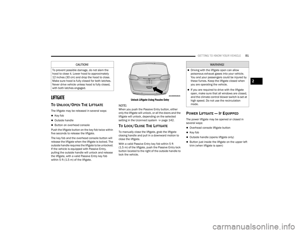
The liftgate may be released in several ways:
Key fob
Outside handle
Button on overhead console
Push the liftgate button on the key fob twice within
five seconds to release the liftgate.
The key fob and the overhead console button will
release the liftgate when the liftgate is locked. The
outside handle requires the liftgate to be unlocked.
If the vehicle is equipped with Passive Entry,
pulling the outside handle will unlock and release
the liftgate, with a valid Passive Entry key fob
within 5 ft (1.5 m) of the liftgate.
Unlock Liftgate Using Passive Entry
NOTE:When you push the Passive Entry button, either
only the liftgate will unlock, or all the doors and the
liftgate will unlock, depending on the selected
setting in the Uconnect system
Úpage 142.
TO LOCK/CLOSE THE LIFTGATE
To manually close the liftgate, grab the liftgate
closing handle and pull in a downward motion to
close the liftgate.
With a valid Passive Entry key fob within 5 ft
(1.5 m) of the liftgate, push the Passive Entry lock
button located to the right of the outside handle to
lock the vehicle.
POWER LIFTGATE — IF EQUIPPED
The power liftgate may be opened or closed in
several ways:
Overhead console liftgate button
Key fob
Outside handle (opens liftgate only)
Button just inside the liftgate on the upper left
trim (when liftgate is open)
CAUTION!
To prevent possible damage, do not slam the
hood to close it. Lower hood to approximately
12 inches (30 cm) and drop the hood to close.
Make sure hood is fully closed for both latches.
Never drive vehicle unless hood is fully closed,
with both latches engaged.
WARNING!
Driving with the liftgate open can allow
poisonous exhaust gases into your vehicle.
You and your passengers could be injured by
these fumes. Keep the liftgate closed when
you are operating the vehicle.
If you are required to drive with the liftgate
open, make sure that all windows are closed,
and the climate control blower switch is set at
high speed. Do not use the recirculation
mode.
2
21_RUV_OM_EN_USC_t.book Page 81
Page 84 of 348

82GETTING TO KNOW YOUR VEHICLE
Using the above ways to open or close the liftgate:
When the liftgate is fully closed, the liftgate will
open
When the liftgate is fully open, the liftgate will
close
When the liftgate is moving, the liftgate will
reverse
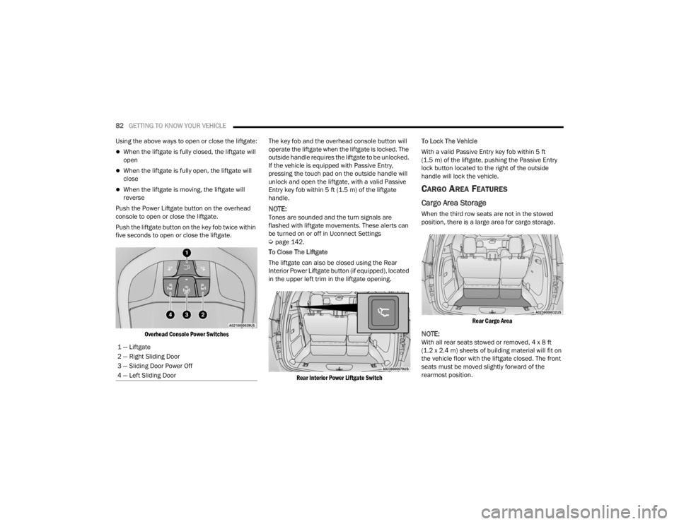
Push the Power Liftgate button on the overhead
console to open or close the liftgate.
Push the liftgate button on the key fob twice within
five seconds to open or close the liftgate.
Overhead Console Power Switches
The key fob and the overhead console button will
operate the liftgate when the liftgate is locked. The
outside handle requires the liftgate to be unlocked.
If the vehicle is equipped with Passive Entry,
pressing the touch pad on the outside handle will
unlock and open the liftgate, with a valid Passive
Entry key fob within 5 ft (1.5 m) of the liftgate
handle.
NOTE:Tones are sounded and the turn signals are
flashed with liftgate movements. These alerts can
be turned on or off in Uconnect Settings
Úpage 142.
To Close The Liftgate
The liftgate can also be closed using the Rear
Interior Power Liftgate button (if equipped), located
in the upper left trim in the liftgate opening.
Rear Interior Power Liftgate Switch
To Lock The Vehicle
With a valid Passive Entry key fob within 5 ft
(1.5 m) of the liftgate, pushing the Passive Entry
lock button located to the right of the outside
handle will lock the vehicle.
CARGO AREA FEATURES
Cargo Area Storage
When the third row seats are not in the stowed
position, there is a large area for cargo storage.
Rear Cargo Area
NOTE:With all rear seats stowed or removed, 4 x 8 ft
(1.2 x 2.4 m) sheets of building material will fit on
the vehicle floor with the liftgate closed. The front
seats must be moved slightly forward of the
rearmost position.
1 — Liftgate
2 — Right Sliding Door
3 — Sliding Door Power Off
4 — Left Sliding Door
21_RUV_OM_EN_USC_t.book Page 82
Page 85 of 348

GETTING TO KNOW YOUR VEHICLE83
STOW ‘N PLACE ROOF RACK — IF EQUIPPED
The crossbars and side rails are designed to carry
weight on vehicles equipped with a luggage rack.
The load must not exceed 150 lb (68 kg), and
should be uniformly distributed over the luggage
rack crossbars.
The crossbars on your vehicle are delivered stowed
within the roof rack side rails. Crossbars should
always be used whenever cargo is placed on the
roof rack. Check the straps frequently to be sure
that the load remains securely attached.
Roof Rack
The Stow ‘N Place roof rack does not increase the
total load carrying capacity of the vehicle. Be sure
the total load of cargo inside the vehicle plus that
on the external rack does not exceed the maximum
vehicle load capacity.
DEPLOYING THE CROSSBARS
1. To deploy the crossbars, completely loosen
the thumb screws at both ends of the
crossbar and lift the crossbar from its stowed
position in the side rail. Repeat with crossbar
on the opposite side.
Thumb Screw
NOTE:The thumb screws cannot be fully removed.
Removing Crossbars
1 — Side Rail
2 — Crossbar
CAUTION!
Use care when removing and handling the
crossbars to prevent damage to the vehicle.
2
21_RUV_OM_EN_USC_t.book Page 83
Page 86 of 348

84GETTING TO KNOW YOUR VEHICLE
2. Bend the crossbar supports at each end, taking care to keep hand clear of pivoting joint.
Slide the thumb screw down.
Bending Pivot
3. Position the crossbars across the roof making sure the letters on the crossbars align with the
matching letters on the side rail.
Positioning Crossbars
4. Once the crossbar is in place, tighten both thumb screws completely.
Installing Crossbars
5. Deploy and tighten the second crossbar to
complete the deployment of the crossbars.
NOTE:The crossbars are not identical and have fixed
deployment positions. Rear crossbar can be
deployed in two different positions.
STOWING THE CROSSBARS
1. Starting with one crossbar, completely loosen the thumb screws at both ends. Lift the
crossbar away from the matching letter to
remove it from the deployed position. Repeat
with the other crossbar.
CAUTION!
Use care when removing and handling the
crossbars to prevent damage to the vehicle.
21_RUV_OM_EN_USC_t.book Page 84
Page 87 of 348

GETTING TO KNOW YOUR VEHICLE85
2. Starting with the one crossbar, bend up the pivot supports at each end.
Crossbar Pivot
3. Then, position the crossbar along the correct side rail. Make sure the letters on the crossbar
align with the matching letters on the side rail.
Stowing Crossbars
4. The crossbar will nest fully within the side rail.
Crossbar To Side Rail
5. Once the driver’s side crossbar is in place,
tighten the thumb screws completely.
Tightening Crossbar
6. Repeat the procedure to stow the second crossbar on the opposite side.
Stowed Crossbars
2
21_RUV_OM_EN_USC_t.book Page 85
Page 88 of 348

86GETTING TO KNOW YOUR VEHICLE
(Continued)
NOTE:
To help control wind noise, stow the crossbars in
the side rails when they are not in use.
If any metallic object is placed over the satellite
radio antenna (if equipped), you may experience
interruption of satellite radio reception.
WARNING!
Cargo must be securely tied down before driving
your vehicle. Improperly secured loads can fly off
the vehicle, particularly at high speeds, resulting
in personal injury or property damage. Follow
the roof rack cautions when carrying cargo on
your roof rack.
CAUTION!
To prevent damage to the roof of your vehicle,
DO NOT carry any loads on the roof rack
without the crossbars deployed. The load
should be secured and placed on top of the
crossbars, not directly on the roof. If it is
necessary to place the load on the roof, place
a blanket or other protective layer between
the load and the roof surface.
To avoid damage to the roof rack and vehicle,
do not exceed the maximum roof rack load
capacity of 150 lb (68 kg). Always distribute
heavy loads as evenly as possible and secure
the load appropriately.
Load should always be secured to cross bars
first, with tie down loops used as additional
securing points if needed. Tie loops are
intended as supplementary tie down points
only. Do not use ratcheting mechanisms with
the tie loops. Check the straps and thumb
wheels frequently to be sure that the load
remains securely attached.
Long loads that extend over the windshield,
such as wood panels or surfboards, or loads
with large frontal area should be secured to
both the front and rear of the vehicle.
Travel at reduced speeds and turn corners
carefully when carrying large or heavy loads
on the roof rack. Wind forces, due to natural
causes or nearby truck traffic, can add sudden
upward lift to a load. This is especially true on
large flat loads and may result in damage to
the cargo or your vehicle.
CAUTION!
21_RUV_OM_EN_USC_t.book Page 86
Page 89 of 348

87
GETTING TO KNOW YOUR INSTRUMENT PANEL
INSTRUMENT CLUSTER
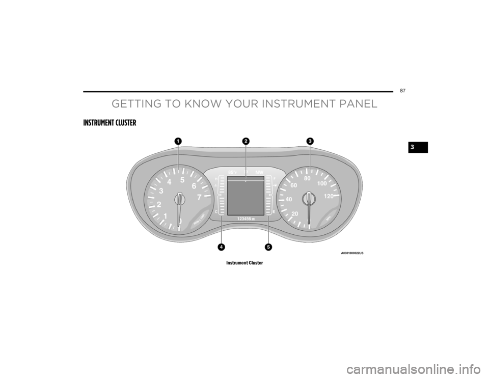
Instrument Cluster
3
21_RUV_OM_EN_USC_t.book Page 87
Page 90 of 348

88GETTING TO KNOW YOUR INSTRUMENT PANEL
INSTRUMENT CLUSTER DESCRIPTIONS
1. Tachometer
Indicates the engine speed in revolutions
per minute (RPM x 1000).
2. Instrument Cluster Display
When the appropriate conditions exist, this
display shows the instrument cluster
display messages
Úpage 89.
3. Speedometer
Indicates vehicle speed.
4. Temperature Gauge
The temperature gauge shows engine
coolant temperature. Any reading within the
normal range indicates that the engine
cooling system is operating satisfactorily.
The gauge can indicate a higher tempera -
ture when driving in hot weather or up
mountain grades. It should not be allowed
to exceed the upper limits of the normal
operating range. 5. Fuel Gauge
The gauge shows the level of fuel in the
fuel tank when the ignition switch is in the
ON/RUN position.
The fuel pump symbol points to
the side of the vehicle where the
fuel door is located.
NOTE:The hard telltales will illuminate for a bulb check
when the ignition is first cycled.
INSTRUMENT CLUSTER DISPLAY
Your vehicle is equipped with an instrument cluster
display, which offers useful information to the
driver. With the ignition in the OFF position (and the
key removed, for vehicles with mechanical key),
opening/closing of a door will activate the display
for viewing, and display the total miles or
kilometers in the odometer. Your instrument
cluster display is designed to display important
information about your vehicle’s systems and
features. Using a driver interactive display located
on the instrument panel, your instrument cluster
display can show you how systems are working and
give you warnings when they are not. The steering
wheel mounted controls allow you to scroll through
and enter the main menus and submenus. You can
access the specific information you want and
make selections and adjustments.
WARNING!
Driving with a hot engine cooling system could
damage your vehicle. If the temperature gauge
reaches “H” pull over and stop the vehicle. Idle
the vehicle with the air conditioner turned off
until the gauge drops back into the normal range
and is no longer red. If the gauge remains on the
“H”, turn the engine off immediately and call an
authorized dealer for service.
WARNING!
A hot engine cooling system is dangerous. You or
others could be badly burned by steam or boiling
coolant. You may want to call an authorized
dealer for service if your vehicle overheats
Úpage 286.
21_RUV_OM_EN_USC_t.book Page 88