2021 CHEVROLET SILVERADO 1500 height
[x] Cancel search: heightPage 254 of 463
Chevrolet Silverado 1500 Owner Manual (GMNA-Localizing-U.S./Canada/
Mexico/Paraguay-14632303) - 2021 - CRC - 11/9/20
Driving and Operating 251
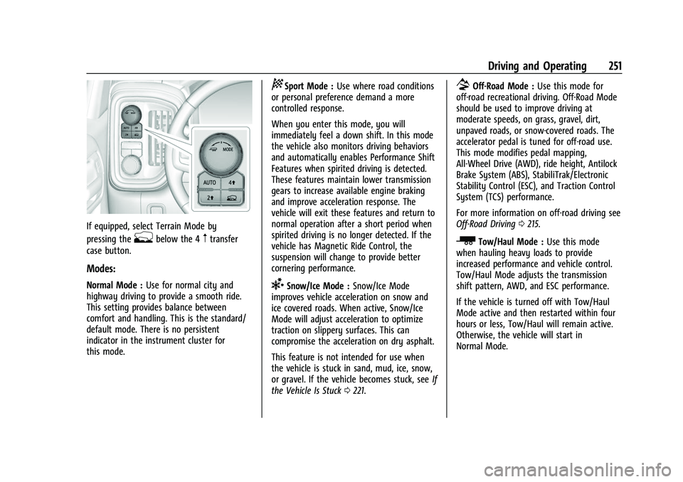
If equipped, select Terrain Mode by
pressing the
gbelow the 4mtransfer
case button.
Modes:
Normal Mode : Use for normal city and
highway driving to provide a smooth ride.
This setting provides balance between
comfort and handling. This is the standard/
default mode. There is no persistent
indicator in the instrument cluster for
this mode.
8Sport Mode : Use where road conditions
or personal preference demand a more
controlled response.
When you enter this mode, you will
immediately feel a down shift. In this mode
the vehicle also monitors driving behaviors
and automatically enables Performance Shift
Features when spirited driving is detected.
These features maintain lower transmission
gears to increase available engine braking
and improve acceleration response. The
vehicle will exit these features and return to
normal operation after a short period when
spirited driving is no longer detected. If the
vehicle has Magnetic Ride Control, the
suspension will change to provide better
cornering performance.
6Snow/Ice Mode : Snow/Ice Mode
improves vehicle acceleration on snow and
ice covered roads. When active, Snow/Ice
Mode will adjust acceleration to optimize
traction on slippery surfaces. This can
compromise the acceleration on dry asphalt.
This feature is not intended for use when
the vehicle is stuck in sand, mud, ice, snow,
or gravel. If the vehicle becomes stuck, see If
the Vehicle Is Stuck 0221.
7Off-Road Mode : Use this mode for
off-road recreational driving. Off-Road Mode
should be used to improve driving at
moderate speeds, on grass, gravel, dirt,
unpaved roads, or snow-covered roads. The
accelerator pedal is tuned for off-road use.
This mode modifies pedal mapping,
All-Wheel Drive (AWD), ride height, Antilock
Brake System (ABS), StabiliTrak/Electronic
Stability Control (ESC), and Traction Control
System (TCS) performance.
For more information on off-road driving see
Off-Road Driving 0215.
_Tow/Haul Mode : Use this mode
when hauling heavy loads to provide
increased performance and vehicle control.
Tow/Haul Mode adjusts the transmission
shift pattern, AWD, and ESC performance.
If the vehicle is turned off with Tow/Haul
Mode active and then restarted within four
hours or less, Tow/Haul will remain active.
Otherwise, the vehicle will start in
Normal Mode.
Page 283 of 463
Chevrolet Silverado 1500 Owner Manual (GMNA-Localizing-U.S./Canada/
Mexico/Paraguay-14632303) - 2021 - CRC - 11/9/20
280 Driving and Operating
LCA warning display will light up in the
corresponding outside side mirror and will
flash if the turn signal is on.
{Warning
LCA does not alert the driver to vehicles
outside of the system detection zones,
pedestrians, bicyclists, or animals. It may
not provide alerts when changing lanes
under all driving conditions. Failure to use
proper care when changing lanes may
result in injury, death, or vehicle damage.
Before making a lane change, always
check mirrors, glance over your shoulder,
and use the turn signals.
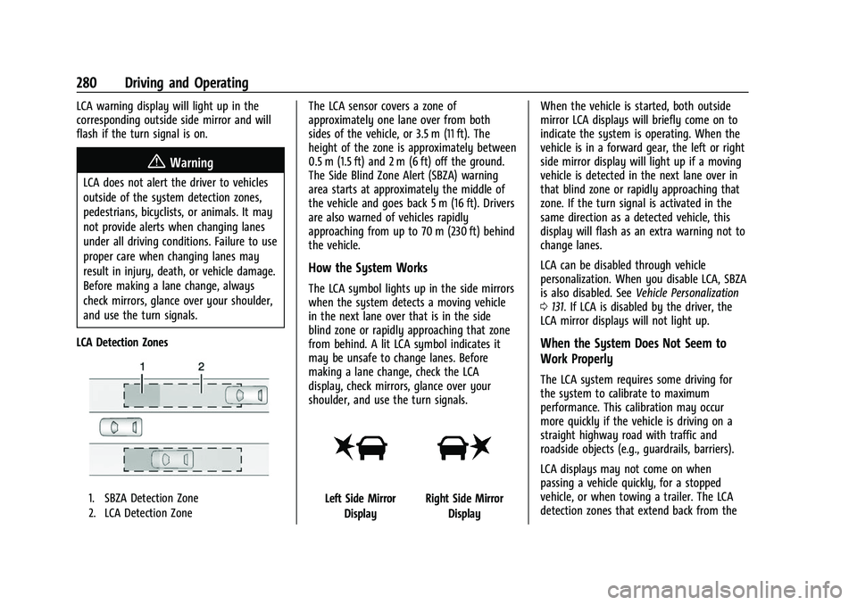
LCA Detection Zones
1. SBZA Detection Zone
2. LCA Detection Zone
The LCA sensor covers a zone of
approximately one lane over from both
sides of the vehicle, or 3.5 m (11 ft). The
height of the zone is approximately between
0.5 m (1.5 ft) and 2 m (6 ft) off the ground.
The Side Blind Zone Alert (SBZA) warning
area starts at approximately the middle of
the vehicle and goes back 5 m (16 ft). Drivers
are also warned of vehicles rapidly
approaching from up to 70 m (230 ft) behind
the vehicle.
How the System Works
The LCA symbol lights up in the side mirrors
when the system detects a moving vehicle
in the next lane over that is in the side
blind zone or rapidly approaching that zone
from behind. A lit LCA symbol indicates it
may be unsafe to change lanes. Before
making a lane change, check the LCA
display, check mirrors, glance over your
shoulder, and use the turn signals.
Left Side Mirror DisplayRight Side Mirror Display When the vehicle is started, both outside
mirror LCA displays will briefly come on to
indicate the system is operating. When the
vehicle is in a forward gear, the left or right
side mirror display will light up if a moving
vehicle is detected in the next lane over in
that blind zone or rapidly approaching that
zone. If the turn signal is activated in the
same direction as a detected vehicle, this
display will flash as an extra warning not to
change lanes.
LCA can be disabled through vehicle
personalization. When you disable LCA, SBZA
is also disabled. See
Vehicle Personalization
0 131. If LCA is disabled by the driver, the
LCA mirror displays will not light up.
When the System Does Not Seem to
Work Properly
The LCA system requires some driving for
the system to calibrate to maximum
performance. This calibration may occur
more quickly if the vehicle is driving on a
straight highway road with traffic and
roadside objects (e.g., guardrails, barriers).
LCA displays may not come on when
passing a vehicle quickly, for a stopped
vehicle, or when towing a trailer. The LCA
detection zones that extend back from the
Page 300 of 463
Chevrolet Silverado 1500 Owner Manual (GMNA-Localizing-U.S./Canada/
Mexico/Paraguay-14632303) - 2021 - CRC - 11/9/20
Driving and Operating 297
Vehicle SeriesTrailer Weight Weight-Distributing Hitch Usage Hitch Distribution
1500 Up to 3 175 kg (7,000 lb) Not Required50%
1500 Over 3 175 kg (7,000 lb) Required50%
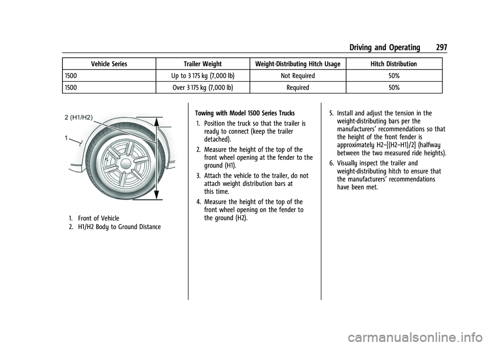
1. Front of Vehicle
2. H1/H2 Body to Ground Distance
Towing with Model 1500 Series Trucks
1. Position the truck so that the trailer is ready to connect (keep the trailer
detached).
2. Measure the height of the top of the front wheel opening at the fender to the
ground (H1).
3. Attach the vehicle to the trailer, do not attach weight distribution bars at
this time.
4. Measure the height of the top of the front wheel opening on the fender to
the ground (H2). 5. Install and adjust the tension in the
weight-distributing bars per the
manufacturers’ recommendations so that
the height of the front fender is
approximately H2−[(H2−H1)/2] (halfway
between the two measured ride heights).
6. Visually inspect the trailer and weight-distributing hitch to ensure that
the manufacturers’ recommendations
have been met.
Page 301 of 463

Chevrolet Silverado 1500 Owner Manual (GMNA-Localizing-U.S./Canada/
Mexico/Paraguay-14632303) - 2021 - CRC - 11/9/20
298 Driving and Operating
MeasurementHeight Example 1500 (mm)
H1 1 000
H2 1 050
H2−H1 50
(H2−H1)/2 25
H2−[(H2−H1)/2] 1 025
Tires
.Do not tow a trailer while using a
compact spare tire on the vehicle.
.Tires must be properly inflated to support
loads while towing a trailer. SeeTires
0 361 for instructions on proper tire
inflation.
Fifth-Wheel and Gooseneck Trailering
Fifth-wheel and gooseneck trailers can be
used with many pickup models. These
trailers place a larger percentage of the
weight (kingpin weight) on the tow vehicle
than conventional trailers. Make sure this
weight does not cause the vehicle to exceed
GAWR or GVWR. Fifth-wheel or gooseneck
kingpin weight should be 15–25% of the
trailer weight up to the maximum amount specified in the trailering chart for the
vehicle. See
“Trailer Weight" under Trailer
Towing 0292.
The hitch should be in the pickup bed so
that its centerline is over or slightly in front
of the rear axle. Take care that it is not so
far forward that it will contact the back of
the cab in sharp turns. This is especially
important for short box pickups. Trailer pin
box extensions and sliding fifth-wheel hitch
assemblies may be used. There should be at
least 15 cm (6 in) of clearance between the
top of the pickup box and the bottom of the
trailer shelf that extends over the box.
Make sure the hitch is attached to the tow
vehicle frame rails. Do not use the pickup
box for support.
Safety Chains
Always attach safety chains between the
vehicle and the trailer. Instructions about
safety chains may be provided by the hitch
manufacturer or by the trailer manufacturer.
If the trailer being towed weighs up to
2 271 kg (5,000 lb) with a factory-installed
step bumper, safety chains may be attached
to the attaching points on the bumper;
otherwise, safety chains should be attached
to holes on the trailer hitch.
Cross the safety chains under the tongue of
the trailer to help prevent the tongue from
contacting the road if it becomes separated
from the hitch. Always leave enough slack in
the safety chains to allow the combination
to turn. Never allow safety chains to drag
on the ground.
Page 312 of 463
Chevrolet Silverado 1500 Owner Manual (GMNA-Localizing-U.S./Canada/
Mexico/Paraguay-14632303) - 2021 - CRC - 11/9/20
Driving and Operating 309
The process stops without saving the
sensor locations if this step takes more
than two minutes.
4. Move to the next tire and repeat Step 3 for each sensor. The horn chirps twice
when all sensors are completed.
5. Return to the vehicle to complete the setup.
Maintenance Reminders
To set up maintenance reminders, touch the
Trailer Maintenance icon. Select Yes to set
up the maintenance reminders for the
Trailer Profile. Follow the on-screen prompts.
The maximum number of reminders is 50.
Select No to return to the previous screen.
Towing Assistance
To set up towing assistance features,
if equipped, touch the Towing
Assistance icon.
Touch Yes to begin set up or touch No to
return to the previous screen.
1. Select the number of axles on the trailer.
2. Enter trailer dimensions as prompted.
3. Follow the on-screen instructions to complete setup for available features.
Transparent Trailer Setup (if equipped)
To complete setup for transparent trailer:
.Trailer Length: 300 cm (118.1 in) –970 cm
(381.8 in). Measure from center of coupler
to furthest rear point on the trailer.
.Trailer Width: 120 cm (47.2 in) –260 cm
(102.3 in). Measure from left edge to
right edge.
.Trailer Height: 1 cm (0.39 in) –450 cm
(177.1 in). Measure from ground to tallest
point.
.Hitching Point Length: 180 cm (70.8 in) –
970 cm (381.8 in). Measure from center of
coupler to middle of tires.
.Trailer Tongue Length: 50 cm (19.6 in) –
220 cm (86.6 in). Measure from center of
coupler to trailer front wall.
.Vehicle Hitch Height: 10 cm (3.9 in) –
100 cm (39.3 in). Measure from ground to
top of coupler.
.Vehicle Hitch Length: 10 cm (3.9 in) –
100 cm (39.3 in). Measure from hitch
receiver to center of ball.
1. If trailer dimensions are out of range, this feature will be unavailable.
2. Ensure rear trailer camera is connected. 3. Follow instructions to drive forward to
complete calibration.
Rear Trailer Guidance Setup (if equipped)
A rear trailer camera must be mounted on
the trailer and electrically connected to the
vehicle before transparent trailer feature can
be used. See Assistance Systems for Parking
or Backing 0266.
Trailer dimensions must be in range to
enable this feature.
.Trailer Length: 300 cm (118.1 in) –970 cm
(381.8 in). Measure from center of coupler
to furthest rear point on the trailer.
1. If trailer dimensions are out of range, this feature will be unavailable.
2. Ensure rear trailer camera is connected.
3. Follow instructions to drive forward to complete calibration.
Jack-Knife Alert Setup (if equipped)
Follow instructions to drive forward to
complete calibration.
Trailer Length Indicator Setup (if
equipped)
Follow instructions to drive forward to
complete calibration.
Page 325 of 463
Chevrolet Silverado 1500 Owner Manual (GMNA-Localizing-U.S./Canada/
Mexico/Paraguay-14632303) - 2021 - CRC - 11/9/20
322 Vehicle Care
Accessories and Modifications
Adding non-dealer accessories or making
modifications to the vehicle can affect
vehicle performance and safety, including
such things as airbags, braking, stability,
ride and handling, emissions systems,
aerodynamics, durability, and electronic
systems like antilock brakes, traction control,
and stability control. These accessories or
modifications could even cause malfunction
or damage not covered by the vehicle
warranty.
Damage to suspension components caused
by modifying vehicle height outside of
factory settings will not be covered by the
vehicle warranty.
Damage to vehicle components resulting
from modifications or the installation or use
of non-GM certified parts, including control
module or software modifications, is not
covered under the terms of the vehicle
warranty and may affect remaining
warranty coverage for affected parts.
GM Accessories are designed to complement
and function with other systems on the
vehicle. See your dealer to accessorize the
vehicle using genuine GM Accessories
installed by a dealer technician.Also, see
Adding Equipment to the
Airbag-Equipped Vehicle 069.
Vehicle Checks
Doing Your Own Service Work
{Warning
It can be dangerous to work on your
vehicle if you do not have the proper
knowledge, service manual, tools,
or parts. Always follow owner’s manual
procedures and consult the service
manual for your vehicle before doing any
service work.
If doing some of your own service work, use
the proper service manual. It tells you much
more about how to service the vehicle than
this manual can. To order the proper service
manual, see Publication Ordering
Information 0436.
This vehicle has an airbag system. Before
attempting to do your own service work,
see Servicing the Airbag-Equipped Vehicle
0 69. If equipped with remote vehicle start, open
the hood before performing any service
work to prevent remote starting the vehicle
accidentally. See
Remote Vehicle Start 020.
Keep a record with all parts receipts and list
the mileage and the date of any service
work performed. See Maintenance Records
0 422.Caution
Even small amounts of contamination can
cause damage to vehicle systems. Do not
allow contaminants to contact the fluids,
reservoir caps, or dipsticks.
Hood
{Warning
For vehicles with auto engine stop/start,
turn the vehicle off before opening the
hood. If the vehicle is on, the engine will
start when the hood is opened. You or
others could be injured.
Page 344 of 463
Chevrolet Silverado 1500 Owner Manual (GMNA-Localizing-U.S./Canada/
Mexico/Paraguay-14632303) - 2021 - CRC - 11/9/20
Vehicle Care 341
Brake Pedal Travel
See your dealer if the brake pedal does not
return to normal height, or if there is a
rapid increase in pedal travel. This could be
a sign that brake service may be required.
Replacing Brake System Parts
Always replace brake system parts with
new, approved replacement parts. If this is
not done, the brakes may not work
properly. The braking performance can
change in many ways if the wrong brake
parts are installed or if parts are improperly
installed.
Brake Pad Life System
When to Change Brake Pads
This vehicle has a system that estimates the
remaining life of the front and rear brake
pads. Brake pad life is displayed in the
Driver Information Center (DIC), along with
a percentage for each axle. The system must
be reset every time the brake pads are
changed.
When the system has determined that the
brake pads need to be replaced, a message
will display, which may include mileage
remaining.Brake pads should always be replaced as
complete axle sets.
How to Reset the Brake Pad Life System
The system will automatically detect when
significantly worn brake pads are replaced.
When the ignition is turned on after new
pads and wear sensors are installed, a
message will display. Follow the prompts to
reset the system.
The brake pad life system can also be
manually reset:
1. Display Brake Pad Life on the DIC. See Driver Information Center (DIC) (Base
Level) 0124 or
Driver Information Center (DIC) (Midlevel
and Uplevel) 0125.
2. Press the thumbwheel or the trip odometer reset stem if the vehicle does
not have DIC buttons. Select front or rear
pads as appropriate.
3. Select YES on the confirmation message, or press the trip odometer reset stem on
a base level DIC. Repeat for pads on the
other axle if they were also replaced.
How to Disable the Brake Pad Life
System
The brake pad life system can be turned off.
This may be necessary if aftermarket brake
pads without wear sensors are installed.
When the system is turned off, the front
and rear brake pad life percentages will not
display. However, the built-in wear
indicators that make a high-pitched warning
sound when the brake pads are worn can
still determine when the pads should be
replaced. See Brakes0340.
To turn off the brake pad life system: 1. Display Brake Pad Life on the DIC. See Driver Information Center (DIC) (Base
Level) 0124 or
Driver Information Center (DIC) (Midlevel
and Uplevel) 0125.
2. Select DISABLE.
To turn the brake pad life system back on,
follow the above steps but select ENABLE in
Step 2.
Page 365 of 463
Chevrolet Silverado 1500 Owner Manual (GMNA-Localizing-U.S./Canada/
Mexico/Paraguay-14632303) - 2021 - CRC - 11/9/20
362 Vehicle Care
Winter Tires
This vehicle was not originally equipped
with winter tires. Winter tires are designed
for increased traction on snow and
ice-covered roads. Consider installing winter
tires on the vehicle if frequent driving on ice
or snow covered roads is expected. See your
dealer for details regarding winter tire
availability and proper tire selection. Also,
seeBuying New Tires 0376.
With winter tires, there may be decreased
dry road traction, increased road noise, and
shorter tread life. After changing to winter
tires, be alert for changes in vehicle
handling and braking.
If using winter tires:
.Use tires of the same brand and tread
type on all four wheel positions.
.Use only radial ply tires of the same size,
load range, and speed rating as the
original equipment tires.
Winter tires with the same speed rating as
the original equipment tires may not be
available for H, V, W, Y, and ZR speed rated
tires. If winter tires with a lower speed
rating are chosen, never exceed the tire's
maximum speed capability.
All-Terrain Tires
This vehicle may have all-terrain or
mud-terrain tires. These tires provide good
performance on most road surfaces, weather
conditions, and for off-road driving. See
Off-Road Driving 0215.
The tread pattern on these tires may wear
more unevenly than other tires. Consider
rotating the tires more frequently than at
12 000 km (7,500 mi) intervals if irregular
wear is noted when the tires are inspected.
See Tire Inspection 0374.
Tire Sidewall Labeling
Useful information about a tire is
molded into the sidewall. The examples
show a typical passenger and light
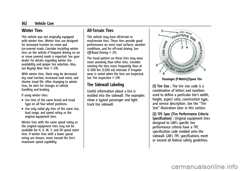
truck tire sidewall.
Passenger (P-Metric)/Spare Tire
(1) Tire Size:The tire size code is a
combination of letters and numbers
used to define a particular tire's width,
height, aspect ratio, construction type,
and service description. See the “Tire
Size” illustration later in this section.
(2) TPC Spec (Tire Performance Criteria
Specification)
:Original equipment tires
designed to GM's specific tire
performance criteria have a TPC
specification code molded onto the
sidewall. GM's TPC specifications meet
or exceed all federal safety guidelines.