2021 AUDI E-TRON electrical system
[x] Cancel search: electrical systemPage 6 of 308

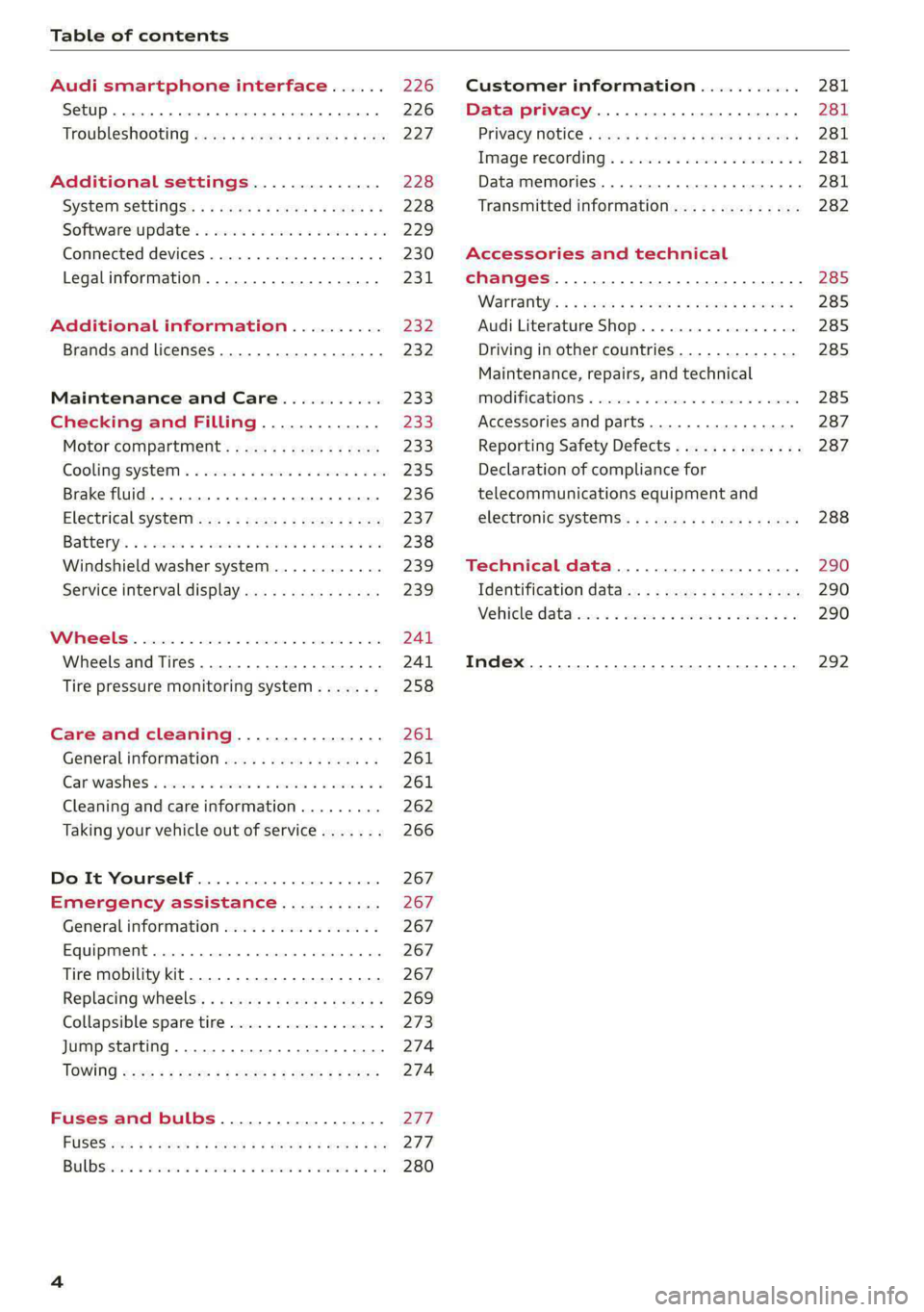
Table of contents
Audi smartphone interface...... 226
Setup... eee eee eee eee 226
Troubleshooting wv s & wees se cows 6 bey 227
Additional settings.............. 228
System Settings: : s eens s i vows ve sews es 228
Software update...............2..-0. 229
Connected devices.............000005 230
Legalinformation................... 231
Additional information.......... 232
Brands and licenses...............--- 232
Maintenance and Care........... 233
Checking and Filling............. 233
Motor'compartment’. sc. ¢ « wcen es oes 233.
CoolingisysteM « x sisws ov sass ov somes & & ane 235
Brake fluid. ........ 0.0.0.0 c eee eee 236
Electrical system <
Battenyis ¢ «sic s 6 wen 2 9 ween oy were 2 ere 238
Windshield washer system...........- 239
Service interval display............... 239
WWINGOIS : ceciices co costes 6 a sncewvs ow oneners 0 at 241
Wheels and Tires . . 241
Tire pressure monitoring system....... 258
Care and cleaning................ 261
Generalinformation................. 261
Car washes « swe: vx awa: oo amin 0 x snanae #2 261
Cleaning and care information......... 262
Taking your vehicle out of service....... 266
Do It Yourself .................... 267
Emergency assistance........... 267
General information................. 267
Equipment............. 0c eee eee 267
Tire mobility kit..................00. 267
Replacing wheels. ........:cceeeeeees 269
Collapsible spare tire..............0.. 273
Jump starting ..............e eee eee 274
IQWING were: worms 5 cee 9 + eee + eee 274
Fuses and bulbs.................. 277
FUSES 3 2 amow 4 meme a 2 mee ay ome 2 277.
Bel DSyonsn = secaais 2s omens a orate vw acct =e aa 280
Customer information........... 281
Data privacy..................008. 281
Privacy MOtiCe « mes x x eee 2 Ree ¢ RES ¥ 281
Image recording): « « sus 2 wanes 2 2 wweem 2 2s 281
Data memories............0..00 eee ee 281
Transmitted information.............. 282
Accessories and technical
changes................ 0.0.02 eee 285
Warranty’: « + esos & + meen & ¢ eee se sees 285
Audi Literature Shop.............000- 285
Driving in other countries............. 285
Maintenance, repairs, and technical
IMOGIFICATIONS « snocue so sume = emmace # m annem 285
Accessories and parts..............-. 287
Reporting Safety Defects.............. 287
Declaration of compliance for
telecommunications equipment and
electronicisysteMms:: s = caws se waa « 2 gems 288
Technical data.................... 290
Identification data................04. 290
Vehicle datas ss nico s ves se oman evs 290
Index ...... 00.0... eee eee 292
Page 9 of 308

4KE012721BF
Quick access
— Audi musicinterface .......... 217
— Audi phone box ............... 177
Socket wz zs sews x 2 uews yo ees sve 78
@ Electromechanical parking brake
BUEtON sgsae «2 came o 2 eawa xo ees 2 98
@0 Selector lever ..............02. 92
@) [START STOP] button ............ 90
@ Steering wheel adjustment ...... 62
@) Lever for:
— Cruise control system ......... 141
— Adaptive cruise assist .......... 144
@4 Connection port for the On Board
Diagnostic System (OBD) ........ 281
@) Hood release ..............00-5 234
@8 Memory function buttons ........ 67
@) Buttons for:
SsLIQWtS | cove & & sonsaws o o amavors & & imamwas 9 0 48
—All-weather lights ............ 48
@8
Luggage compartment lid button . 39
@9 Exterior mirror adjustment ...... 52
60 Buttons for:
— Power windows .............. 43
—Child safety lock .............. 42
() Tips
Some the equipment listed here is only instal-
led in certain models or is available as an op-
tion.
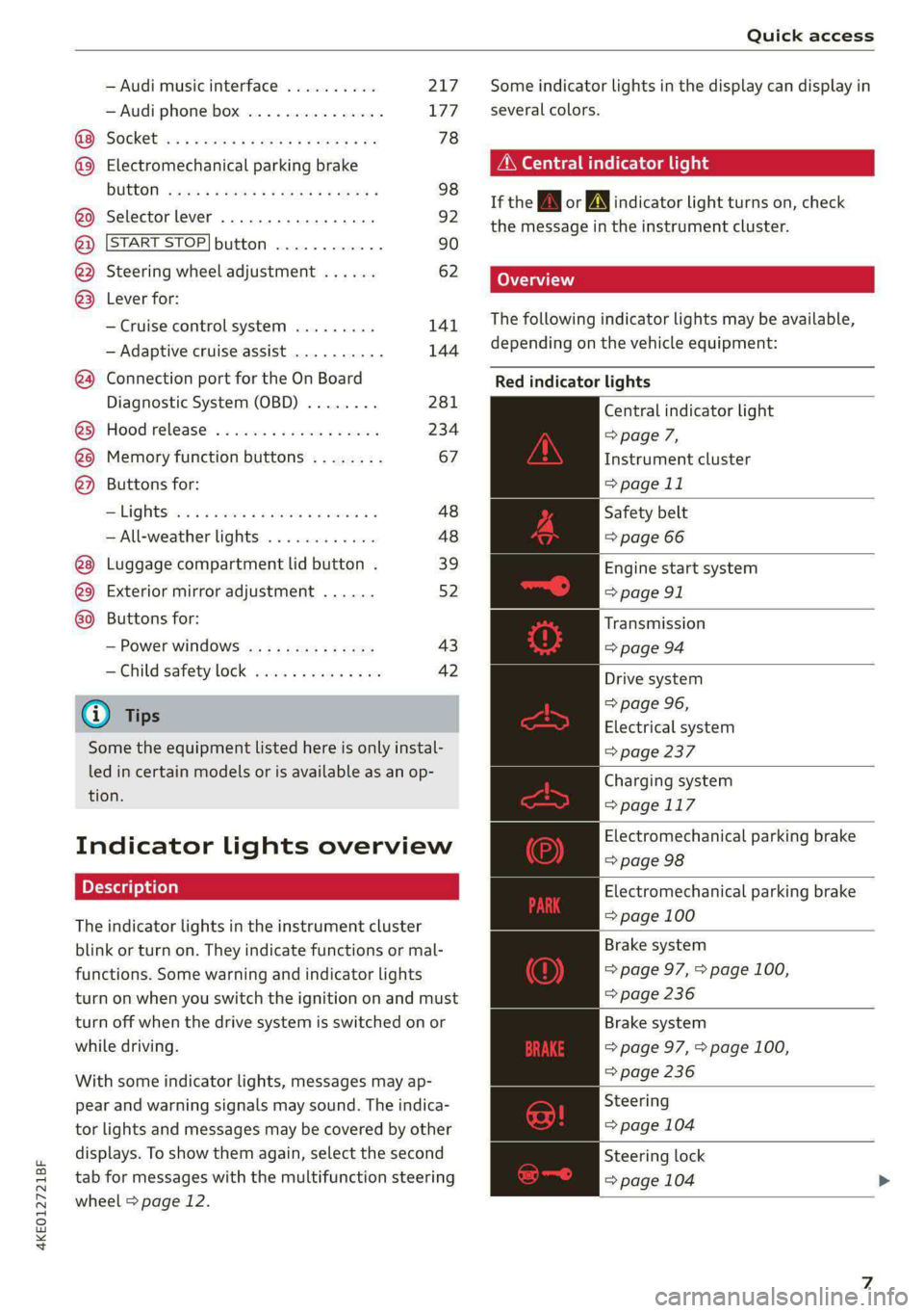
Indicator lights overview
The indicator lights in the instrument cluster
blink or turn on. They indicate functions or mal-
functions. Some warning and indicator lights
turn on when you switch the ignition on and must
turn off when the drive system is switched on or
while driving.
With some indicator lights, messages may ap-
pear and warning signals may sound. The indica-
tor lights and messages may be covered by other
displays. To show them again, select the second
tab for messages with the multifunction steering
wheel > page 12.
Some indicator lights in the display can display in
several colors.
A\ Central indicator light
If the A or indicator light turns on, check
the message in the instrument cluster.
The following indicator lights may be available,
depending on the vehicle equipment:
Red indicator lights
Central indicator light
=> page 7,
Instrument cluster
=> page 11
Safety belt
=> page 66
Engine start system
=> page 91
Transmission
=>page 94
Drive system
=> page 96,
Electrical system
=> page 237
Charging system
=>page 117
Electromechanical parking brake
=> page 98
Electromechanical parking brake
=> page 100
Brake system
=> page 97, > page 100,
=> page 236
Brake system
=> page 97, > page 100,
=> page 236
Steering
=> page 104
Steering lock
=> page 104
Page 10 of 308

Quick access
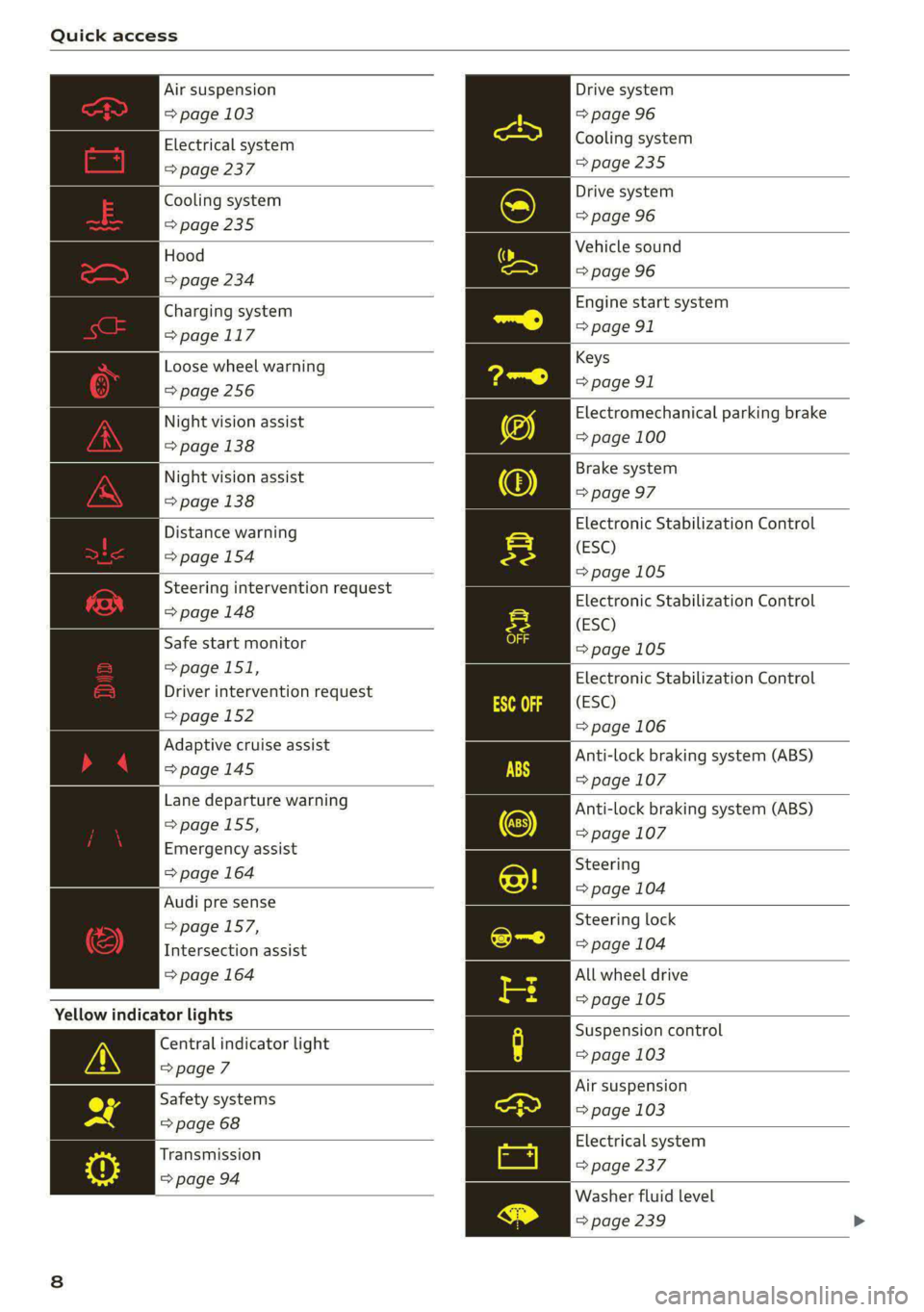
Air suspension
=> page 103
Electrical system
=> page 237
Cooling system
=> page 235
Hood
=> page 234
Charging system
=>page 117
Loose wheel warning
=>page 256
Night vision assist
=> page 138
Night vision assist
=> page 138
Distance warning
=> page 154
Steering intervention request
=> page 148
Safe start monitor
=>page 151,
Driver intervention request
=>page 152
Adaptive cruise assist
=>page 145
Lane departure warning
=> page 155,
Emergency assist
=> page 164
Audi pre sense
=>page 157,
Intersection assist
=> page 164
Yellow indicator lights
Central indicator light
=>page 7
Safety systems
=> page 68
Transmission
=> page 94
Drive system
=> page 96
Cooling system
>page 235
Drive system
=> page 96
Vehicle sound
=> page 96
Engine start system
=> page 91
Keys
=> page 91
Electromechanical parking brake
=> page 100
Brake system
=> page 97
Electronic Stabilization Control
(ESC)
=>page 105
Electronic Stabilization Control
(ESC)
=>page 105
Electronic Stabilization Control
(ESC)
=> page 106
Anti-lock braking system (ABS)
=> page 107
Anti-lock braking system (ABS)
=> page 107
Steering
=> page 104
Steering lock
=> page 104
All wheel drive
=>page 105
Suspension control
= page 103
Air suspension
=> page 103
Electrical system
= page 237
Washer fluid level
=> page 239
Page 15 of 308

4KE012721BF
Instrument cluster
Reducing the display
Depending on the vehicle equipment, you can
hide the central area in the instrument cluster.
> Select on the instrument cluster: vehicle func-
tions tab > EE] button > Reduced display.
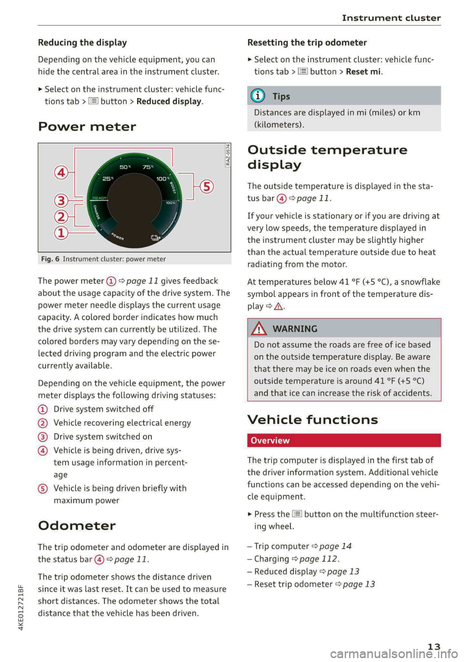
Power meter
RAZ-0574) fi
@
Fig. 6 Instrument cluster: power meter
The power meter @ > page 11 gives feedback
about the usage capacity of the drive system. The
power meter needle displays the current usage
capacity. A colored border indicates how much
the drive system can currently be utilized. The
colored borders may vary depending on the se-
lected driving program and the electric power
currently available.
Depending on the vehicle equipment, the power
meter displays the following driving statuses:
Drive system switched off
Vehicle recovering electrical energy
Drive system switched on
®©O&O Vehicle is being driven, drive sys-
tem usage information in percent-
age
© Vehicle is being driven briefly with
maximum power
Odometer
The trip odometer and odometer are displayed in
the status bar @) > page 11.
The trip odometer shows the distance driven
since it was last reset. It can be used to measure
short distances. The odometer shows the total
distance that the vehicle has been driven.
Resetting the trip odometer
> Select on the instrument cluster: vehicle func-
tions tab > EJ button > Reset mi.
(i) Tips
Distances are displayed in mi (miles) or km
(kilometers).
Outside temperature
display
The outside temperature is displayed in the sta-
tus bar @) > page 11.
If your vehicle is stationary or if you are driving at
very low speeds, the temperature displayed in
the instrument cluster may be slightly higher
than the actual temperature outside due to heat
radiating from the motor.
At temperatures below 41 °F (+5 °C), a snowflake
symbol appears in front of the temperature dis-
play > A\.
ZA\ WARNING
Do not assume the roads are free of ice based
on the outside temperature display. Be aware
that there may be ice on roads even when the
outside temperature is around 41 °F (+5 °C)
and that ice can increase the risk of accidents.
Vehicle functions
Coa (ai)
The trip computer is displayed in the first tab of
the driver information system. Additional vehicle
functions can be accessed depending on the vehi-
cle equipment.
> Press the E] button on the multifunction steer-
ing wheel.
— Trip computer > page 14
— Charging > page 112.
— Reduced display > page 13
— Reset trip odometer > page 13
13
Page 34 of 308

Opening and closing
Opening and closing
Central locking
(eT e e eeu)
ZA WARNING
— If you leave the vehicle, switch the ignition
off and take the key with you. This applies
particularly when children remain in the ve-
hicle. Otherwise, children could start the ve-
hicle or operate electrical equipment (such
as power windows), which increases the risk
of an accident.
— Applies to vehicles with anti-theft alarm sys-
tem: When the vehicle is locked from the
outside, no one - especially children - should
remain in the vehicle, because the windows
can no longer open from the inside
= page 35, Anti-theft alarm system.
Locked doors make it more difficult for
emergency workers to enter the vehicle,
which puts lives at risk.
All doors and the luggage compartment lid can
be centrally unlocked and locked at once. You can
select in the MMI if the entire vehicle or only the
driver's door should unlock when unlocking the
vehicle > page 33. The turn signals flash twice
when you unlock the vehicle and flash once when
you lock the vehicle. If they do not flash when
locking, check if all doors and lids are closed.
Depending on the vehicle equipment, you may
have different options for centrally unlocking and
locking your vehicle.
— Vehicle key > page 37
— Sensors in the door handles > page 37
— Lock cylinder in the driver's door > page 35
— Interior central locking switch > page 34
Vehicle key
The term “vehicle key” refers to the remote con-
trol key or convenience key*. The convenience
key* is a remote control key with special func-
tions > page 37 and > page 90.
32
Power closing*
When closing a door or the luggage compart-
ment lid, you only have to let it fall lightly into
the latch. It then closes automatically > A\.
Automatic locking
If you unlock the vehicle but then do not open
any of the doors, the luggage compartment, or
the hood within a short period time, the vehicle
locks again automatically. This feature prevents
the vehicle from being accidentally left unlocked
for a long period of time.
Automatic locking (Auto Lock)
The Auto Lock function locks all doors and the
luggage compartment lid once the speed has ex-
ceeded approximately 9 mph (15 km/h). The ve-
hicle will unlock again if the unlock function in
the central locking switch is pressed, the “P” gear
is engaged, or the ignition is switched off.
You can open the doors individually from the in-
side by pulling the door handle one time. To open
the rear doors individually, you must pull the
door handle twice.
In the event of a crash with airbag deployment,
the doors will also automatically unlock to allow
access to the vehicle.
Unintentionally locking yourself out
Only lock your vehicle when all of the doors and
the luggage compartment lid are closed and
there is no key in the vehicle. This reduces the
risk of locking yourself out accidentally.
The
following features help to reduce the risk of
locking your vehicle key in the vehicle:
— If the driver's door is open, the vehicle cannot
be locked by pressing the & button on the re-
mote control key or by touching the locking
sensor* on a door.
— If the vehicle key that was used most recently is
inside the luggage compartment, the luggage
compartment lid will automatically open again
after it closes > ©.
— If the vehicle key that was last used is detected
inside the vehicle, then the vehicle cannot be
locked from the outside > ©.
Page 73 of 308

4KE012721BF
Sitting correctly and safely
— PASSENGER AIR BAG OFF #; ON ® indi-
cator light in the headliner:this indicates if the
front passenger's airbag is activated or deacti-
vated
- indicator light in the instrument cluster:
this monitors the function of the Advanced Air-
bag System components to ensure they are
functioning correctly
How the components function together
The passenger occupant detection sensor in the
front passenger's seat detects if the front pas-
senger's seat is occupied. The passenger occu-
pant detection sensor measures the electrical ca-
pacity on the front passenger’s seat. The pas-
senger's airbag is activated or deactivated de-
pending on the electrical capacity that is meas-
ured.
The passenger's airbag is activated if:
— The electrical capacity is higher than the
threshold stored in the control module
— The electrical capacity is the same as or greater
than the electrical capacity of a typical adult
The passenger's airbag is deactivated if:
— The electrical capacity is lower than the thresh-
old stored in the control module
— The electrical capacity is the same as or less
than the electrical capacity of a typical one-
year-old child in a child safety seat that has
been used for certification in accordance with
FMVSS 208
If the front passenger's airbag is activated, the
PASSENGER AIR BAG ON @ indicator light
will turn on. If the front passenger's airbag is de-
activated, the PASSENGER AIR BAG OFF #;
indicator light will turn on.
The deployment force of the front airbags adapts
based on whether or not the safety belt is used
and the distance between the seat and the steer-
ing wheel/instrument panel. For example, if a
person is too close to the front airbag, the front
airbag will deploy with less force to help reduce
the risk of injury.
Meaning of PASSENGER AIR BAG OFF 3%, ON
® indicator light
When the ignition is switched on, the system de-
tects whether the front passenger's seat is occu-
pied. PASSENGER AIR BAG OFF #;, ON @
will turn on for several seconds during this proc-
ess. Then it will indicate whether the front pas-
senger's airbag is activated or deactivated.
— PASSENGER AIR BAG OFF #%;: the front
passenger's airbag is deactivated and will not
deploy in the event of an accident.
— PASSENGER AIR BAG ON ®: the front pas-
senger's airbag is activated and could deploy in
the event of an accident.
If a change to the occupancy status of the front
passenger's seat is detected
PASSENGER AIR BAG OFF #; ON @ will
flash for several seconds and will then display the
status of the front passenger's airbag.
Always make sure the indicator light corresponds
to the occupancy of the front passenger's seat.
— An adult or individual of similar size in the
front passenger's seat: the front passenger's
airbag must be activated, therefore
PASSENGER AIR BAG ON ® must remain
turned on.
— An individual of smaller size (for example, an
adolescent or small adult) in the front pas-
senger's seat: the front passenger's airbag
must be activated, so
PASSENGER AIR BAG ON ® must stay on.
— Child in a child safety seat on the front pas-
senger's seat: the front passenger's airbag
must be deactivated, so
PASSENGER AIR BAG OFF #; must stay on.
— Front passenger's seat not occupied: the front
passenger's airbag must be deactivated, so
PASSENGER AIR BAG OFF #; must stay on.
ZA\ WARNING
— An adult or a person with a small stature
(such as a young person or small adult) seat-
ed on the front passenger's seat will not be
protected by the passenger's airbag in the
event of a collision if the passenger's airbag
71
Page 80 of 308

Storage and convenience
Storage and convenience
Power sources
When the ignition is switched on, you may be
able to use multiple power sources for external
devices, depending on the vehicle equipment.
12 volt sockets
You can connect electrical accessories to the 12
volt sockets. The power usage from the sockets
must not exceed a total of 120 watts. Do not
connect multiple devices to the sockets in the ve-
hicle at the same time.
The 12 volt sockets are labeled with the 12V
symbol. They are located in the front center con-
sole, in the rear, and on the side trim panel in the
luggage compartment.
USB ports
Applies to: vehicles with USB port
You can charge mobile devices using the USB
ports. The USB ports are labeled with the «> or
[4 symbol or CHARGE ONLY.
| Z\ WARNING
— To reduce the risk of fatal injury, store all
connected devices securely when driving so
that they do not move around inside the ve-
hicle when braking or in the event of an acci-
dent.
— Incorrect usage can lead to serious injuries
or burns. To reduce the risk of injuries, never
leave children unattended in the vehicle
with the vehicle key.
@) Note
— Read the operating manuals for the con-
nected devices.
—To reduce the risk of damage to the vehicle
electrical system, never attempt to charge
the vehicle battery by connecting accesso-
ries that provide power to the power sour-
ces.
— Do not connect any device whose network
class (voltage) does not match the network
class designed for the socket.
78
— Disconnect the connectors from the power
sources carefully to reduce the risk of dam-
aging them.
@ Tips
Do not connect any other devices to the sock-
ets when using the compressor* provided by
the factory > page 267. The power consump-
tion in the sockets may be temporarily ex-
ceeded when using the compressor*.
Cup holders
Applies to: vehicles with cup holders
4
2
RAZ-1177,
Fig. 66 Rear center armrest”: cup holders
Cup holders in the front center console
> Slide the cover (4) back, if necessary.
> Fold the cup holder @) outward.
Cup holders in the rear center armrest*
> Fold the center armrest* downward.
> To open the cup holders (@), tap on the strip on
the cover.
> To close the cup holders, slide them back and
push the top of the cover down.
Page 96 of 308

Driving
Requirements
— Driving program “S” > page 93 or the dynamic
Audi drive select* mode must be selected
=> page 102.
— The boost function is available > page 93.
Using Launch Control
— Press the brake pedal with your left foot and
hold it all the way down for at least one second.
— With the brake pedal pressed, press the accel-
erator pedal all the way down with your right
foot at the same time.
— As soon as the colored edge of the power meter
actively flashes, remove your foot from the
brake pedal.
ZA WARNING
Only use Launch Control when road and traffic
conditions allow it and other road users will
not be endangered or impacted by your driv-
ing and the vehicle's acceleration. The driving
wheels could spin and the vehicle could
swerve, especially on slick or slippery road
surfaces, which increases the risk of an acci-
dent.
@) Note
When accelerating using Launch Control, all
vehicle components are subject to heavy
loads. This can result in increased wear.
G) Tips
After accelerating using the Launch Control,
the temperature of some vehicle components
may increase greatly. If that happens, the
function will not be available for a few mi-
nutes to reduce the risk of damage. After a
cool-down period, Launch Control will be
available again.
Messages
& Transmission: malfunction! Safely stop vehi-
cle
Do not continue driving. Stop the vehicle as soon
as possible in a safe location and secure it so it
does not roll > page 91. See an authorized Audi
94
dealer or authorized Audi Service Facility for as-
sistance.
i Selector lever: malfunction! Gear change on-
ly possible if using both shift paddles.
There is a system malfunction in the selector lev-
er. You can continue driving with restricted func-
tion. The selector lever is not working. Gears can
only be selected by tapping both shift paddles at
the same time when the vehicle is stationary. The
“P” gear is automatically engaged when you
switch off the drive system. Drive to an author-
ized Audi dealer or authorized Audi Service Facili-
ty immediately to have the malfunction correct-
ed.
i P button: malfunction! Auto P when engine
off. Please contact Service
There is a malfunction in the "P" button on the
selector lever. The “P” gear is automatically en-
gaged when you switch off the drive system.
Drive to an authorized Audi dealer or authorized
Audi Service Facility immediately to have the
malfunction corrected.
i Danger of rolling away! P not possible.
Please apply parking brake
Drive system
aa da eee
Vehicles with an electric drive system are pow-
ered by an electric motor. The drive power de-
pends on the temperature and the charge level of
the high-voltage battery.
The vehicle is able to recover energy by using “re-
cuperation”. The electric drive system operates
like a generator and converts a large portion of
kinetic energy into electrical energy that is stored
in the high-voltage battery. The vehicle is braked
during recuperation, which is similar to the en-
gine braking effect on a vehicle with a combus-
tion engine. This will happen automatically when
you press the brake pedal while driving in “D”
gear, or when you remove your foot from the ac-
celerator pedal.