Page 129 of 350

4K8012721BF
High-voltage system
Meaning
Do not use any travel adapters.
Do not use any power strips.
, Do not use any charging cables with
oo, damage to the electronics or the
connecting wires.
Operate the Audi charging system
in single-phase power supplies.
Grounding instructions
Audi charging systems must be grounded. If it
should malfunction or break down, grounding
provides a path of least resistance for electric
current to reduce the risk of electric shock. Audi
charging systems are equipped with a cord hav-
ing an equipment grounding conductor anda
grounding plug. The plug must be plugged into
an appropriate outlet that is properly installed
and grounded in accordance with all local codes
and ordinances.
Z\ WARNING
Improper connection of the equipment-
grounding conductor is able to result in a risk
of electric shock. Check with a qualified elec-
trician or serviceman if you are in doubt as to
whether the product is properly grounded. Do
not modify the plug provided with the product
— if it will not fit the outlet, have a proper out-
let installed by a qualified electrician.
Applies to: vehicles with plug-in hybrid drive
ki
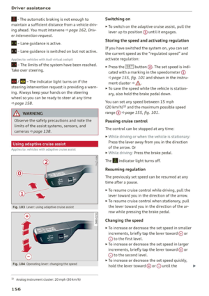
Fig. 86 Luggage compartment: transport bag
Always store the charging equipment securely
before transporting.
> Open the luggage compartment lid > page 43.
> Stow the charging equipment in the transport
bag.
>» Secure the transport bag using the tie-downs
=> page 85.
> Close the luggage compartment lid.
ZA\ WARNING
If the charging equipment is not secured or
positioned correctly, it can slide out of place
and endanger vehicle occupants when brak-
ing, when changing directions, or in a colli-
sion.
— Only transport charging equipment in the
transport bag in the luggage compartment
and never unsecured or in the passenger
compartment.
@) Note
Always lift or carry the Audi charging system
as one unit and never by the cables.
127
Page 130 of 350

High-voltage system
Audi e-tron compact charging system
Applies to: vehicles with Audi e-tron compact charging system
a oho
RAZ-0726|
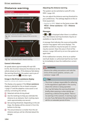
Fig. 87 Audi e-tron compact charging system: components
(example)
Observe the safety precautions > page 120, Im-
portant safety precautions.
The Audi e-tron compact charging system can be
used for charging with a household or industrial
socket. Depending on the country and the vehicle
equipment, the following accessories may be
available:
@ Control unit
@ Vehicle cable with vehicle charging connector
@) Power cable with power plug for household
sockets
@ Power cable with power plug for industrial
sockets
The vehicle cable is securely connected to the
control unit. The power cable is plugged into the
upper end of the control unit and can be switched
=> page 133.
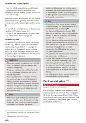
Control unit overview
© | On/Off button @, charging power lev-
el and LED
© _ |Status LED:
a Power supply/household
connection
& | Vehicle
0 Control panel
Reset ® 9
Charging
Note the instructions for charging > page 122.
128
Fig. 88 Audi e-tron compact charging system: control unit
Requirement: the correct power plug must be in-
stalled > page 133.
— Insert the plug into the socket.
— Plug the vehicle charging connector into the ve-
hicle charging port.
— The charging process e will start automatically.
— Once the charging process has completed, un-
lock the vehicle and remove the vehicle charg-
ing connector from the vehicle charging port.
Adjusting the charging power level
The control unit automatically recognizes the
voltage and the available current strength. You
can set whether you would like to charge with full
or reduced charging power. The last setting that
was selected will be saved and used again the
next time the vehicle is charged. If multiple
items are connected to the power circuit, the
charging current may be reduced when charging
at a power outlet. This can help to prevent the
electrical equipment from overheating.
Before charging, always check if the charging
power setting that was selected last is still suita-
ble.
—To set the charging power level, press and hold
the ® button © © fig. 88 for at least two sec-
onds.
After the charging power level is set, the status
LEDs (, and [) will flash green one time. The
selected value (50% or 100%) is displayed on the
left or right side of the ® button.
Page 131 of 350

4K8012721BF
High-voltage system
Control unit: status and malfunction indicators
Indicator lights Meaning Solution
O Green The charger is ready to charge, | Starting the charging process
but is not charging. => page 122. CQ Off
O & Off
O 0 Off
9 Off
© Flashing green | The vehicle is being charged
O QO Off with the ground conductor
O B oft monitor activated.
O 6 off
9 Off
© Flashing green | The power cable has overheat- | After the cable cools down, the malfunc-
© a Yellow ed. Possible cause of the mal- | tion will be automatically cleared. Until it
O B oft function: a multi-phase socket | cools down, charging performance will be
O 6 of is being used in single-phase | reduced. If the malfunction continues,
mode. The charging perform- | have the power supply/household con-
© Off ance will be reduced. nection checked by a qualified electrician.
®) Flashing green |The control unit has overheat- | After the control unit cools down, the
O QA Off ed. The charging performance | malfunction will be automatically
will be reduced. cleared. Never leave the control panel in
O & Off P
@ 0 vel direct sunlight for long periods or time.
enow Until it cools down, charging performance
© Off will be reduced. If the malfunction con-
tinues, have the control unit checked by
an authorized Audi dealer or authorized
Audi Service Facility.
@ Yellow The charger is connected to
O O Off the vehicle. The high-voltage
O B oft battery is charged and the
charging process has ended
O 0 off successfully, or the vehicle is
© Off not requesting a charging pro-
cedure.
O Red The power cable has overheat- | After the cable cools down, the malfunc-
© Q Yellow ed. The charging process has __| tion will be automatically cleared and the
O B oft been interrupted. charging process will resume. If the mal-
O 6 of function continues, have the control unit
6 checked by an authorized Audi dealer or
Off
authorized Audi Service Facility, or have
the power supply/household connection
checked by a qualified electrician.
129
Page 132 of 350

High-voltage system
Indicator lights Meaning Solution
O Red The control unit has overheat- | After the control unit cools down, the
O A Off ed. The charging process has_ | malfunction will be automatically cleared
O @ oft been interrupted. and the charging process will resume.
Never leave the control panel in direct
© 0 Yellow sunlight for long periods or time. If the
9 Off malfunction continues, have the control
unit checked by an authorized Audi dealer
or authorized Audi Service Facility.
oO Red The charging infrastructure of | After the power supply/household con-
© Flashing yellow |the power supply/household | nection stabilizes, the malfunction will be
O @ oft connection is restricted. Possi- | automatically cleared and the charging
O 6 of ble cause of the malfunction: | process will resume. If the malfunction
low voltage or poor power fre- | continues, have the power supply/house-
9 Off quency. The charging process _ | hold connection checked by a qualified
has been interrupted. electrician.
O Red There is a malfunction inthe | After the vehicle charging system stabiliz-
O QO Off vehicle charging system. The | es, the malfunction will be automatically
© B Flashing yellow charging process has been in- | cleared and the charging process will re-
O 6 off terrupted. sume. If the malfunction continues, have
the vehicle checked by an authorized Audi
9° Off dealer or authorized Audi Service Facility.
O Red The power cable or vehicle ca- | Have the power or vehicle cable replaced
O QO Off ble is faulty. Possible cause of | by an authorized Audi dealer or author-
O 2 oft the malfunction: the coding ized Audi Service Facility.
. resistance of the power or ve-
© 0) Flashing yellow hicle cable is not compatible.
o Off The charging process has been
interrupted.
O Red There is a malfunction in the | End the charging process at the vehicle
O O Off vehicle charging system. The | and remove the vehicle cable from the ve-
@ 2 Red charging process has been in- |hicle charging port. Disconnect the charg-
O 0 oft terrupted. er from the power supply and reconnect it
after 60 seconds. Restart the charging
© Off process > page 122. If the malfunction
continues, have the vehicle checked by an
authorized Audi dealer or authorized Audi
Service Facility.
oO Red There is an overvoltage inthe | Disconnect the charger from the power
® 4 Flashing red charging infrastructure of the |supply and reconnect it after 60 seconds.
O 2B oft power supply/household con- | If the malfunction continues, have the
O 6 off nection. The charging process | power supply/household connection
© wi has been interrupted. checked by a qualified electrician.
130
Page 133 of 350

4K8012721BF
High-voltage system
Indicator lights Meaning Solution
© Red The control unit has atechni- | Disconnect the charger from the power
O A Off cal malfunction. The charging | supply and reconnect it after 60 seconds.
O @B oft process has been interrupted. |If the malfunction continues, have the
@ 30 Red control unit checked by an authorized
Audi dealer or authorized Audi Service Fa-
© Off cility.
© Red The control unit has a techni- | Disconnect the charger from the power
O QO Off cal malfunction (self-test supply and reconnect it after 60 seconds.
O B oft failed). The charging process | If the malfunction continues, have the
. has been interrupted. control unit checked by an authorized
@ 0 Flashing red Audi dealer or authorized Audi Service Fa-
9 Off cility.
© Red The charging infrastructure of | Have the control unit checked by an au-
@ QC Red the power supply/household | thorized Audi dealer or authorized Audi
@ Bre connection is insufficient: the | Service Facility, and have the power sup-
O 0 of ground conductor is interrupt- | ply/household connection checked by a
ed or not present. The ground | qualified electrician. Do not use the pow-
© Off conductor monitor has inter- | er supply/household connector until the
rupted the charging process. | malfunction is corrected.
© Red The indicator light in the reset | Have the control unit replaced by an au-
@ X Red button on the control unit is | thorized Audi dealer or authorized Audi
@ & Red faulty. The charging process _| Service Facility.
@ 6 Red has been interrupted.
9 Off
O Red The control unit has detected | Press and hold the © button for at least
@ X Red residual current. The charging | two seconds. If the malfunction contin-
@ 2 Red process has been interrupted. | ues, have the control unit checked by an
@ 6 Red authorized Audi dealer or authorized Audi
Service Facility, and have the power sup-
9 Flashing red ply/household connection checked by a
qualified electrician.
O Red The charging infrastructure is | Disconnect the charger from the power
© 1 Flashing red wired incorrectly. The charging | supply. Have the power supply/household
© @ Flashing red process has been interrupted. | connection checked by a qualified electri-
© {) Flashing red can.
9 Off
O Red The control unit has atechni- | Disconnect the charger from the power
@ A Red cal malfunction. Possible supply and reconnect it after 60 seconds.
@ Bred cause of the malfunction: soft- | If the malfunction continues, have the
@ & Red ware error or the load relay control unit checked by an authorized
© Red has been switched incorrectly. | Audi dealer or authorized Audi Service Fa-
The charging process has been
interrupted.
cility, and have the power supply/house-
hold connection checked by a qualified
electrician.
131
Page 134 of 350

High-voltage system
Indicator lights Meaning Solution
@ Flashing red The control unit has a serious | Have the control unit replaced by an au-
O Q Off malfunction. The charging thorized Audi dealer or authorized Audi
O @ oft process has been interrupted. | Service Facility.
@ § Red
9 Off
O Off The indicator light in the Have the control unit replaced by an au-
@ X Red On/Off button on the control | thorized Audi dealer or authorized Audi
@ S& Red unit is faulty. The charging Service Facility.
@ 6 Red process has been interrupted.
© Red
Technical Data
Output 9.6 kw
Current rating 40 A single phase
System voltage 120V-240V
Power frequency 50 Hz/60 Hz
Overvoltage category (IEC 60664) II
Short-time current rating (EN
61439-1)
<10 kA eff.
Power plug versions NEMA 6-30; NEMA 6-50; NEMA 14-30; NEMA 14-50; NEMA
S15
Integrated residual-current device /AC: 20 mA; DC: 56 mA
Vehicle charging connector Type 1
Protection class I
IP Code 55 (USA: Enclosure 3)
Control unit mass 5.3 lbs - 7.7 lbs (2.4 - 3.5 kg)
Control unit dimensions (height x
width x depth)
12.2 inx 4.1 in x 2.8 in (310 mm x 105 mm x 72 mm)
@) Tips
—The device runs a self test after power has
been restored to the control unit. If a self
test is successful, all indicator lights will il-
luminate green for two seconds.
— The Audi e-tron compact charging system is
designed for charging at sockets with a volt-
age of 120 V/240 V. If your socket has a dif-
ferent voltage, contact and authorized Audi
dealer or authorized Audi Service Facility.
— If your Audi e-tron compact charging sys-
tem has a fixed connection, meaning can be
connected directly to the power supply
132
without a power cable, contact a qualified
electrician or an authorized Audi dealer or
authorized Audi Service Facility.
— The system complies with United States FCC
regulations and ISED regulations
=> page 330.
Page 135 of 350

4K8012721BF
High-voltage system
g or attac g the cable
icles with Audi charging system
Applies to:
B4G-0681 Nn?
— Only change cables in a dry environment.
— The Audi charging system may only be used
as a complete unit consisting of the power
cables, the control unit, and the vehicle ca-
ble. Depending on the country, the total
length of the power cable, control panel and
vehicle cable may be restricted, for example
to 24.6 feet (7.5 m) in the USA. Audi recom-
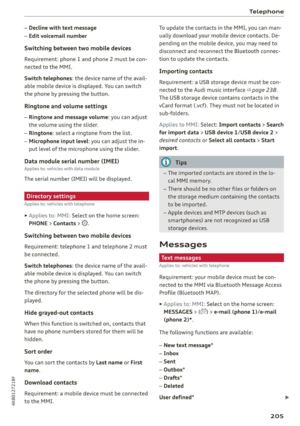
Fig. 89 Control unit: removing and attaching the cable
Requirements:
> The charging process for the high-voltage bat-
tery must be ended > page 123.
> The vehicle charging connector must be re-
moved from the vehicle charging port.
> The power cable must be removed from the
socket.
Loosening the cable
» If necessary, loosen the screw @) using the
screwdriver provided.
> Lift the lever @ all the way up.
> Pull the connector @) out just until you feel re-
sistance.
> Close the lever @ until it is resting on the con-
nector @).
» Remove the connector (2) completely.
Attaching the cable
> Lift the lever @ up slightly.
> Insert the connector (2) into the control unit
just until you feel resistance.
> Lift the lever @ all the way up.
> Insert the connector (2) all the way into the
control unit.
> Close the lever @).
> Tighten the screw @) using the screwdriver pro-
vided.
A WARNING
— Note the warnings for charging > A in
Charging on page 123.
— Before switching a cable, always unplug the
power cable from the socket.
mends using only cables approved by Audi.
Gi) Tips
The power cable with the power connector for
industrial sockets and the Audi charging sys-
tem control unit are designed to work togeth-
er. Changing the power cable to another con-
nector type may reduce the available charging
power of the entire system. Limitations on
the ability to transfer power (current capacity)
depending on the phase and the number of
available phases may affect the available
charging power.
Wall clip
Applies to: vehicles with plug-in hybrid drive and wall mount
clip
RAZ-0638,
Fig. 90 Wall mount clip: securing the Audi charging system
Securing the Audi charging system
> First insert the control unit in the bottom tabs
on the wall mount clip and then into the upper
tabs.
> Push the control unit in the direction of the ar-
row toward the rear > fig. 90 and let it lock into
place.
> Wrap the excess length of cable around the
charging connector mount (@) when you are not
charging the high-voltage battery.
> Plug the power cable into the socket @).
133
Page 136 of 350
High-voltage system
>» After charging, you can hook the vehicle charg-
ing connector to the charging connector mount
©.
Locking and unlocking the Audi charging
system
> You can lock or unlock the Audi charging sys-
tem using the key provided by turning it to the
lock position @) or the unlock position ©).
Removing the Audi charging system
> Remove the power cable connector from the
socket (2).
> Unwind the cable from the charging connector
mount @).
> To loosen the control unit from the bracket,
push the locking mechanism (@) upward.
ZX WARNING
Observe the safety precautions in the assem-
bly instructions for the wall mount clip.
134