2020 YAMAHA TRICITY 300 connect ass
[x] Cancel search: connect assPage 13 of 114
Safety information
1-4
1
able only from a Yamaha dealer, have
been designed, tested, and approved
by Yamaha for use on your vehicle.
Many companies with no connection
to Yamaha manufacture parts and ac-
cessories or offer other modifications
for Yamaha vehicles. Yamaha is not in
a position to test the products that
these aftermarket companies produce.
Therefore, Yamaha can neither en-
dorse nor recommend the use of ac-
cessories not sold by Yamaha or
modifications not specifically recom-
mended by Yamaha, even if sold and
installed by a Yamaha dealer.
Aftermarket Parts, Accessories, an
d
Mo difications
While you may find aftermarket prod-
ucts similar in design and quality to
genuine Yamaha accessories, recog-
nize that some aftermarket accesso-
ries or modifications are not suitable
because of potential safety hazards to
you or others. Installing aftermarket
products or having other modifications
performed to your vehicle that change
any of the vehicle’s design or operation
characteristics can put you and others at greater risk of serious injury or
death. You are responsible for injuries
related to changes in the vehicle.
Keep the following guidelines in mind,
as well as those provided under “Load-
ing” when mounting accessories.
Never install accessories or carry
cargo that would impair the per-
formance of your vehicle. Careful-
ly inspect the accessory before
using it to make sure that it does
not in any way reduce ground
clearance or cornering clearance,
limit suspension travel, steering
travel or control operation, or ob-
scure lights or reflectors.
• Accessories fitted to the han- dlebar or the front fork area can
create instability due to improp-
er weight distribution or aerody-
namic changes. If accessories
are added to the handlebar or
front fork area, they must be as
lightweight as possible and
should be kept to a minimum.
• Bulky or large accessories may seriously affect the stability of
the vehicle due to aerodynamic
effects. Wind may attempt to lift the vehicle, or the vehicle may
become unstable in cross
winds. These accessories may
also cause instability when
passing or being passed by lar-
ge vehicles.
• Certain accessories can dis- place the operator from his or
her normal riding position. This
improper position limits the
freedom of movement of the
operator and may limit control
ability, therefore, such accesso-
ries are not recommended.
Use caution when adding electri-
cal accessories. If electrical ac-
cessories exceed the capacity of
the vehicle’s electrical system, an
electric failure could result, which
could cause a dangerous loss of
lights or engine power.
Aftermarket Tires an d Rims
The tires and rims that came with your
vehicle were designed to match the
performance capabilities and to pro-
vide the best combination of handling,
braking, and comfort. Other tires, rims,
sizes, and combinations may not be
UBX9E0E0.book Page 4 Monday, January 20, 2020 10:54 AM
Page 49 of 114
Instrument and control functions
5-18
5
EAU80200
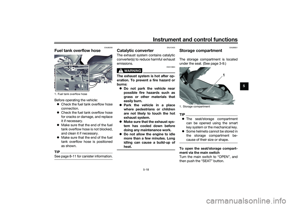
Fuel tank overflow hoseBefore operating the vehicle:
Check the fuel tank overflow hose
connection.
Check the fuel tank overflow hose
for cracks or damage, and replace
it if necessary.
Make sure that the end of the fuel
tank overflow hose is not blocked,
and clean it if necessary.
Make sure that the end of the fuel
tank overflow hose is positioned
as shown.TIPSee page 8-11 for canister information.
EAU13435
Catalytic converterThe exhaust system contains catalytic
converter(s) to reduce harmful exhaust
emissions.
WARNING
EWA10863
The exhaust system is hot after op-
eration. To prevent a fire hazar d or
b urns:
Do not park the vehicle near
possi ble fire hazar ds such as
g rass or other materials that
easily burn.
Park the vehicle in a place
where pe destrians or chil dren
are not likely to touch the hot
exhaust system.
Make sure that the exhaust sys-
tem has cooled down before
d oin g any maintenance work.
Do not allow the en gine to id le
more than a few minutes. Lon g
i d lin g can cause a buil d-up of
heat.
EAU89051
Stora ge compartmentThe storage compartment is located
under the seat. (See page 3-9.)TIP The seat/storage compartment
can be opened using the smart
key system or the mechanical key.
Some helmets cannot be stored in
the storage compartment be-
cause of their size or shape.To open the seat/storag e compart-
ment via the main switch
Turn the main switch to “OPEN”, and
then push the “SEAT” button.
1. Fuel tank overflow hose
1
1. Storage compartment
1
UBX9E0E0.book Page 18 Monday, January 20, 2020 10:54 AM
Page 51 of 114
Instrument and control functions
5-20
5
EAU14895
A djustin g the shock a bsor ber
assem blies
WARNING
EWA10211
Always a djust both shock a bsor ber
assem blies equally, otherwise poor
han dlin g an d loss of sta bility may re-
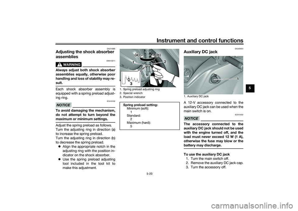
sult.Each shock absorber assembly is
equipped with a spring preload adjust-
ing ring.NOTICE
ECA10102
To avoi d d amag ing the mechanism,
d o not attempt to turn b eyond the
maximum or minimum settin gs.Adjust the spring preload as follows.
Turn the adjusting ring in direction (a)
to increase the spring preload.
Turn the adjusting ring in direction (b)
to decrease the spring preload.
Align the appropriate notch in the
adjusting ring with the position in-
dicator on the shock absorber.
Use the spring preload adjusting
tool included in the tool kit to
make this adjustment.
EAU49454
Auxiliary DC jackA 12-V accessory connected to the
auxiliary DC jack can be used when the
main switch is on.NOTICE
ECA15432
The accessory connecte d to the
auxiliary DC jack shoul d not b e used
with the en gine turne d off, an d the
loa d must never excee d 12 W (1 A),
otherwise the fuse may blow or the
b attery may dischar ge.To use the auxiliary DC jack
1. Turn the main switch off.
2. Remove the auxiliary DC jack cap.
3. Turn the accessory off.
1. Spring preload adjusting ring
2. Special wrench
3. Position indicator
Sprin g preloa d settin g:
Minimum (soft):
1
Standard: 2
Maximum (hard): 51 2345
1
2
3(a)
(a) (b) (b)
(a) (b)
1. Auxiliary DC jack
1
UBX9E0E0.book Page 20 Monday, January 20, 2020 10:54 AM
Page 93 of 114
![YAMAHA TRICITY 300 2020 Owners Manual Periodic maintenance an d a djustment
8-33
8
connect the positive lea
d b efore
connectin g the ne gative lea d.
[ECA16842]
4. After installation, make sure that
the battery leads are properly con-
ne YAMAHA TRICITY 300 2020 Owners Manual Periodic maintenance an d a djustment
8-33
8
connect the positive lea
d b efore
connectin g the ne gative lea d.
[ECA16842]
4. After installation, make sure that
the battery leads are properly con-
ne](/manual-img/51/51928/w960_51928-92.png)
Periodic maintenance an d a djustment
8-33
8
connect the positive lea
d b efore
connectin g the ne gative lea d.
[ECA16842]
4. After installation, make sure that
the battery leads are properly con-
nected to the battery terminals.NOTICE
ECA16531
Always keep the b attery charged .
Storin g a dischar ged battery can
cause permanent battery damag e.
EAU89081
Replacin g the fusesThe main fuse and the fuse boxes,
which contain the fuses for the individ-
ual circuits, are located behind panel A.
(See page 8-9.)TIPTo access the main fuse, remove the
starter relay cover as shown.1. Starter relay cover
2. Spare main fuse
3. Main fuse
2 2
3 2
3
1
1. Backup fuse
2. Radiator fan motor fuse
3. Ignition fuse
4. ABS control unit fuse
5. Signaling system fuse
6. Grip warmer fuse
7. Spare fuse
8. Headlight fuse
9. ABS motor fuse
10.ABS solenoid fuse
11.Hazard fuse
12.Auxiliary DC jack fuse
13.Answer back fuse
14.Standing assist battery fuse
15.Standing assist fuse
14157
910111213
7
123465
7
8
UBX9E0E0.book Page 33 Monday, January 20, 2020 10:54 AM
Page 109 of 114
Consumer information
11-2
11
The model label is affixed to the inside
of the storage compartment. (See
page 5-18.) Record the information on
this label in the space provided. This
information will be needed when order-
ing spare parts from a Yamaha dealer.
EAU69910
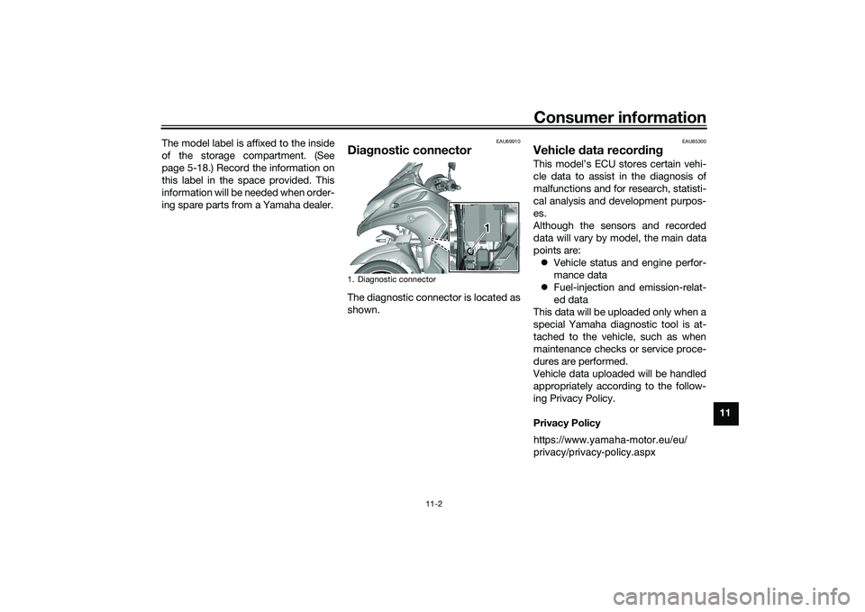
Dia
gnostic connectorThe diagnostic connector is located as
shown.
EAU85300
Vehicle data recor din gThis model’s ECU stores certain vehi-
cle data to assist in the diagnosis of
malfunctions and for research, statisti-
cal analysis and development purpos-
es.
Although the sensors and recorded
data will vary by model, the main data
points are:
Vehicle status and engine perfor-
mance data
Fuel-injection and emission-relat-
ed data
This data will be uploaded only when a
special Yamaha diagnostic tool is at-
tached to the vehicle, such as when
maintenance checks or service proce-
dures are performed.
Vehicle data uploaded will be handled
appropriately according to the follow-
ing Privacy Policy.
Privacy Policy
1. Diagnostic connector
1 1
https://www.yamaha-motor.eu/eu/
privacy/privacy-policy.aspx
UBX9E0E0.book Page 2 Monday, January 20, 2020 10:54 AM
Page 111 of 114
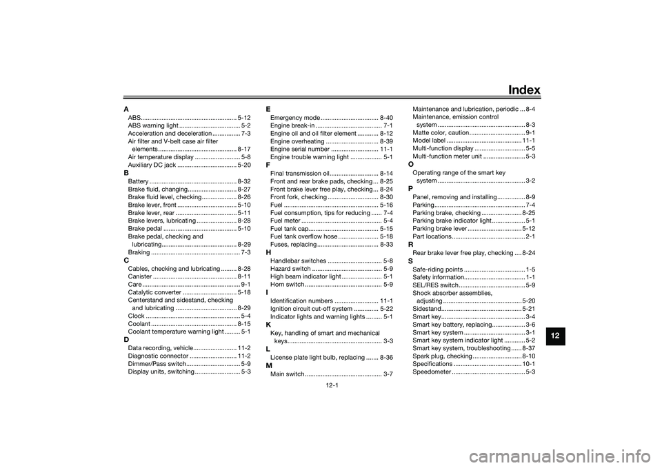
12-1
12
Index
AABS....................................................... 5-12
ABS warning light ................................... 5-2
Acceleration and deceleration ................ 7-3
Air filter and V-belt case air filter
elements ............................................. 8-17
Air temperature display .......................... 5-8
Auxiliary DC jack .................................. 5-20BBattery .................................................. 8-32
Brake fluid, changing............................ 8-27
Brake fluid level, checking.................... 8-26
Brake lever, front .................................. 5-10
Brake lever, rear ................................... 5-11
Brake levers, lubricating ....................... 8-28
Brake pedal .......................................... 5-10
Brake pedal, checking and lubricating........................................... 8-29
Braking ................................................... 7-3CCables, checking and lubricating ......... 8-28
Canister ................................................ 8-11
Care ........................................................ 9-1
Catalytic converter ............................... 5-18
Centerstand and sidestand, checking and lubricating ................................... 8-29
Clock ...................................................... 5-4
Coolant ................................................. 8-15
Coolant temperature warning light ......... 5-1DData recording, vehicle......................... 11-2
Diagnostic connector ........................... 11-2
Dimmer/Pass switch............................... 5-9
Display units, switching .......................... 5-3
EEmergency mode ................................. 8-40
Engine break-in ...................................... 7-1
Engine oil and oil filter element ............ 8-12
Engine overheating .............................. 8-39
Engine serial number ........................... 11-1
Engine trouble warning light .................. 5-1FFinal transmission oil............................ 8-14
Front and rear brake pads, checking ... 8-25
Front brake lever free play, checking ... 8-24
Front fork, checking ............................. 8-30
Fuel ...................................................... 5-16
Fuel consumption, tips for reducing ...... 7-4
Fuel meter .............................................. 5-4
Fuel tank cap........................................ 5-15
Fuel tank overflow hose ....................... 5-18
Fuses, replacing ................................... 8-33HHandlebar switches ............................... 5-8
Hazard switch ........................................ 5-9
High beam indicator light ....................... 5-1
Horn switch ............................................ 5-9IIdentification numbers ......................... 11-1
Ignition circuit cut-off system .............. 5-22
Indicator lights and warning lights ......... 5-1KKey, handling of smart and mechanical keys...................................................... 3-3LLicense plate light bulb, replacing ....... 8-36MMain switch ............................................ 3-7 Maintenance and lubrication, periodic ... 8-4
Maintenance, emission control
system .................................................. 8-3
Matte color, caution................................ 9-1
Model label ........................................... 11-1
Multi-function display ............................. 5-5
Multi-function meter unit ........................ 5-3
OOperating range of the smart key system .................................................. 3-2PPanel, removing and installing ................ 8-9
Parking.................................................... 7-4
Parking brake, checking ....................... 8-25
Parking brake indicator light ................... 5-1
Parking brake lever ............................... 5-12
Part locations.......................................... 2-1RRear brake lever free play, checking .... 8-24SSafe-riding points ................................... 1-5
Safety information................................... 1-1
SEL/RES switch ...................................... 5-9
Shock absorber assemblies, adjusting ............................................. 5-20
Sidestand.............................................. 5-21
Smart key................................................ 3-4
Smart key battery, replacing................... 3-6
Smart key system ................................... 3-1
Smart key system indicator light ............ 5-2
Smart key system, troubleshooting ...... 8-37
Spark plug, checking ............................ 8-10
Specifications ....................................... 10-1
Speedometer .......................................... 5-3
UBX9E0E0.book Page 1 Monday, January 20, 2020 10:54 AM