2020 YAMAHA TRICITY 300 Storage
[x] Cancel search: StoragePage 1 of 114

DIC183
MWD300 (Tricity 300)
1
2
3
4
5
6
7
8
9
10
11
12
BX9-F8199-E0
Read this manual carefully
before operating this vehicle.
MOTORCYCLE
OWNER’S MANUAL
Specifications
Consumer information
Vehicle care and storage
Periodic maintenance and adjustment
For your safety – pre-operation checks
Instrument and control functions Standing assist
Smart key system Description
Safety information
Operation and important riding points Index
[English (E)]
Page 8 of 114

Table of contentsSafety information ............................ 1-1
Further safe-riding points ............... 1-5
Description ....................................... 2-1
Left view ......................................... 2-1
Right view ....................................... 2-2
Controls and instruments ............... 2-3
Smart key system ........................... 3-1
Smart key system ........................... 3-1
Operating range of the smart key system......................................... 3-2
Handling of the smart key and mechanical keys ......................... 3-3
Smart key ....................................... 3-4
Replacing the smart key battery..... 3-6
Main switch .................................... 3-7
Stan din g assist ................................. 4-1
Standing assist ............................... 4-1
Instrument an d control functions ... 5-1
Indicator lights and warning
lights............................................ 5-1
Multi-function meter unit ................ 5-3
Handlebar switches ........................ 5-8
Front brake lever .......................... 5-10
Brake pedal .................................. 5-10
Rear brake lever ........................... 5-11
Parking brake lever ....................... 5-12
ABS .............................................. 5-12 Traction control system ................ 5-13
Fuel tank cap ................................ 5-15
Fuel ............................................... 5-16
Fuel tank overflow hose ................ 5-18
Catalytic converter ........................ 5-18
Storage compartment ................... 5-18
Adjusting the shock absorber
assemblies ................................. 5-20
Auxiliary DC jack ........................... 5-20
Sidestand ...................................... 5-21
Ignition circuit cut-off system ....... 5-22
For your safety – pre-operation
checks ............................................... 6-1
Operation an d important ri din g
points ................................................. 7-1
Engine break-in ............................... 7-1
Starting the engine .......................... 7-2
Starting off ...................................... 7-3
Acceleration and deceleration ........ 7-3
Braking ............................................ 7-3
Tips for reducing fuel consumption ................................ 7-4
Parking ............................................ 7-4
Perio dic maintenance an d
a d justment ........................................ 8-1
Tool kit ............................................ 8-2
Periodic maintenance charts .......... 8-3 Periodic maintenance chart for the
emission control system ............. 8-3
General maintenance and lubrication chart .......................... 8-4
Removing and installing the
panel............................................ 8-9
Checking the spark plug............... 8-10
Canister ........................................ 8-11
Engine oil and oil filter element..... 8-12
Why Yamalube.............................. 8-14
Final transmission oil .................... 8-14
Coolant ......................................... 8-15
Air filter and V-belt case air filter elements .................................... 8-17
Checking the throttle grip free play ............................................ 8-21
Valve clearance............................. 8-21
Tires .............................................. 8-22
Cast wheels .................................. 8-23
Checking the front brake lever
free play..................................... 8-24
Checking the rear brake lever free play..................................... 8-24
Checking the parking brake ......... 8-25
Checking the front and rear brake pads ................................ 8-25
Checking the brake fluid level ...... 8-26
Changing the brake fluid .............. 8-27
Checking the V-belt ...................... 8-27
Checking and lubricating the cables ........................................ 8-28UBX9E0E0.book Page 1 Monday, January 20, 2020 10:54 AM
Page 9 of 114
Table of contents
Checking and lubricating the
throttle grip and cable ................8-28
Lubricating the front and rear brake levers................................8-28
Checking and lubricating the
brake pedal ................................8-29
Checking and lubricating the centerstand and sidestand ........8-29
Checking the front fork..................8-30
Checking the steering ...................8-31
Lubricating the steering bearings .....................................8-31
Checking the wheel bearings ........8-31
Battery ...........................................8-32
Replacing the fuses .......................8-33
Vehicle lights .................................8-35
Replacing a turn signal light bulb ............................................8-35
Replacing the license plate light bulb ............................................8-36
Troubleshooting ............................8-36
Troubleshooting chart ...................8-38
Emergency mode .........................8-40
Vehicle care an d stora ge .................9-1
Matte color caution .........................9-1
Care .................................................9-1
Storage ............................................9-3 Specifications
................................. 10-1
Consumer information ................... 11-1
Identification numbers .................. 11-1
Diagnostic connector.................... 11-2
Vehicle data recording .................. 11-2
In dex ................................................ 12-1
UBX9E0E0.book Page 2 Monday, January 20, 2020 10:54 AM
Page 17 of 114
Description
2-2
2
EAU10421
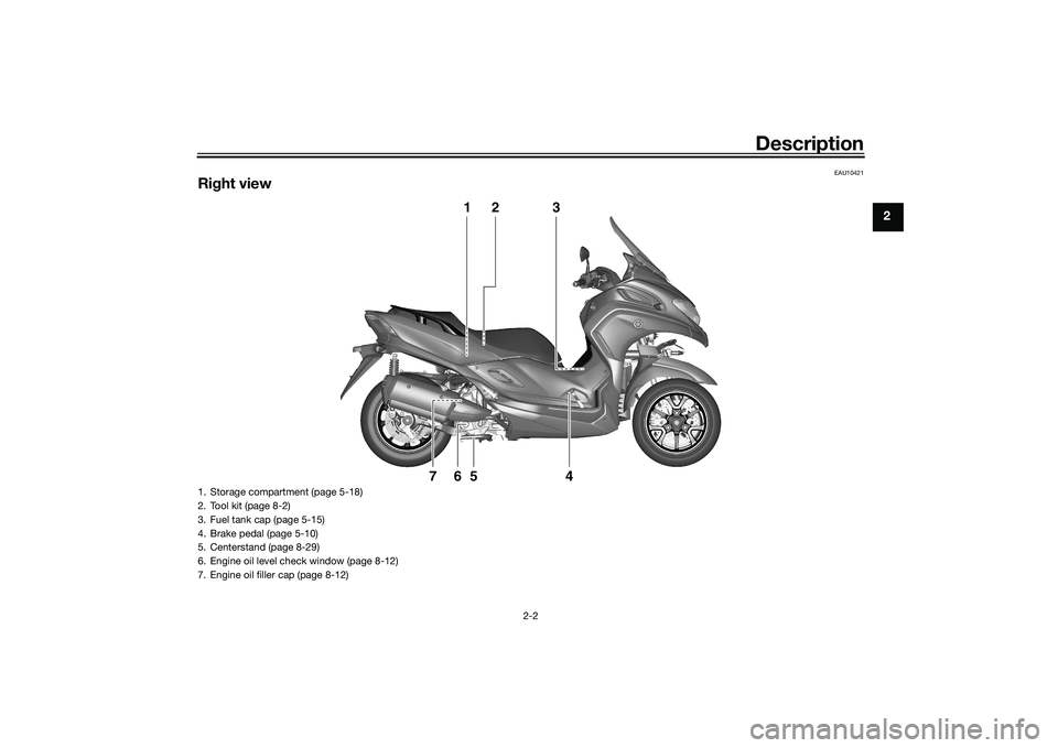
Right view
1
2
3
4
5
6
7
1. Storage compartment (page 5-18)
2. Tool kit (page 8-2)
3. Fuel tank cap (page 5-15)
4. Brake pedal (page 5-10)
5. Centerstand (page 8-29)
6. Engine oil level check window (page 8-12)
7. Engine oil filler cap (page 8-12)
UBX9E0E0.book Page 2 Monday, January 20, 2020 10:54 AM
Page 20 of 114
Smart key system
3-2
3
You are carryin g or usin g com-
munication equipment such as
ra dios or mo bile phones in
close proximity of the smart key
The smart key is in contact with
or covere d b y a metallic o bject
Other vehicles equippe d with a
smart key system are near by
In such situations, move the smart
key to another location an d perform
the operation ag ain. If it still does
not work, operate the vehicle in
emer gency mo de. (See pag e 8-40.)
TIPTo preserve vehicle battery power, the
smart key system turns off approxi-
mately 9 days after the vehicle was last
used (the answer-back function is dis-
abled). In this situation, simply push
the main switch knob to turn the smart
key system back on.
EAU76452
Operating ran ge of the smart
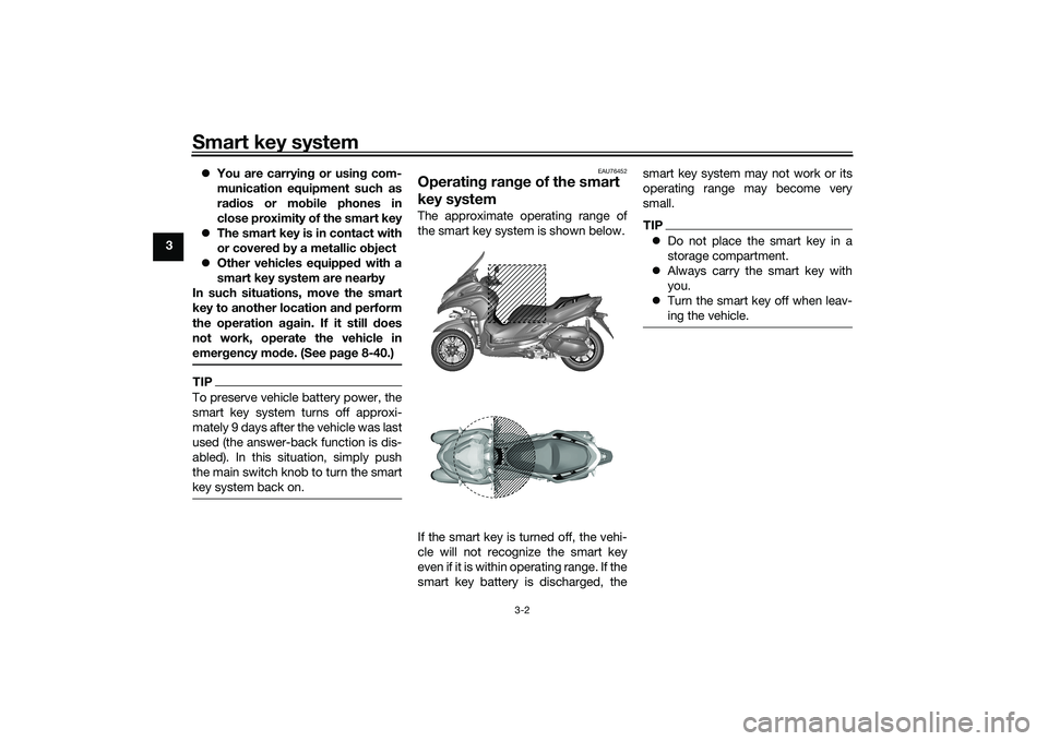
key systemThe approximate operating range of
the smart key system is shown below.
If the smart key is turned off, the vehi-
cle will not recognize the smart key
even if it is within operating range. If the
smart key battery is discharged, the smart key system may not work or its
operating range may become very
small.
TIP
Do not place the smart key in a
storage compartment.
Always carry the smart key with
you.
Turn the smart key off when leav-
ing the vehicle.
UBX9E0E0.book Page 2 Monday, January 20, 2020 10:54 AM
Page 49 of 114
Instrument and control functions
5-18
5
EAU80200
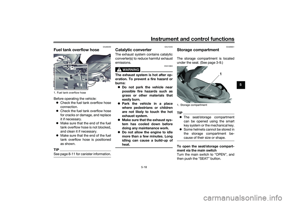
Fuel tank overflow hoseBefore operating the vehicle:
Check the fuel tank overflow hose
connection.
Check the fuel tank overflow hose
for cracks or damage, and replace
it if necessary.
Make sure that the end of the fuel
tank overflow hose is not blocked,
and clean it if necessary.
Make sure that the end of the fuel
tank overflow hose is positioned
as shown.TIPSee page 8-11 for canister information.
EAU13435
Catalytic converterThe exhaust system contains catalytic
converter(s) to reduce harmful exhaust
emissions.
WARNING
EWA10863
The exhaust system is hot after op-
eration. To prevent a fire hazar d or
b urns:
Do not park the vehicle near
possi ble fire hazar ds such as
g rass or other materials that
easily burn.
Park the vehicle in a place
where pe destrians or chil dren
are not likely to touch the hot
exhaust system.
Make sure that the exhaust sys-
tem has cooled down before
d oin g any maintenance work.
Do not allow the en gine to id le
more than a few minutes. Lon g
i d lin g can cause a buil d-up of
heat.
EAU89051
Stora ge compartmentThe storage compartment is located
under the seat. (See page 3-9.)TIP The seat/storage compartment
can be opened using the smart
key system or the mechanical key.
Some helmets cannot be stored in
the storage compartment be-
cause of their size or shape.To open the seat/storag e compart-
ment via the main switch
Turn the main switch to “OPEN”, and
then push the “SEAT” button.
1. Fuel tank overflow hose
1
1. Storage compartment
1
UBX9E0E0.book Page 18 Monday, January 20, 2020 10:54 AM
Page 103 of 114
Vehicle care and stora ge
9-2
9
chemicals such as, solvents,
g
asoline, rust removers, b rake
flui d, or antifreeze, etc.
Before washin g
1. Park the vehicle out of direct sun- light and allow it to cool. This will
help avoid water spots.
2. Make sure all caps, covers, elec- trical couplers and connectors are
tightly installed.
3. Cover the muffler end with a plas- tic bag and a strong rubber band.
4. Pre-soak stubborn stains like in- sects or bird droppings with a wet
towel for a few minutes.
5. Remove road grime and oil stains with a quality degreasing agent
and a plastic-bristle brush or
sponge. NOTICE: Do not use
d eg reasin g a gent on areas re-
quirin g lu brication such as
seals, gaskets, an d wheel axles.
Follow pro duct instructions.
[ECA26290]
Washin g
1. Rinse off any degreaser and spray down the vehicle with a garden
hose. Use only enough pressure
to do the job. Avoid spraying wa-
ter directly into the muffler, instru-
ment panel, air inlet, or other inner
areas such as underseat storage
compartments.
2. Wash the vehicle with a quality au- tomotive-type detergent mixed
with cool water and a soft, clean
towel or sponge. Use an old tooth-
brush or plastic-bristle brush for
hard-to-reach places. NOTICE:
Use col d water if the vehicle has
b een exposed to salt. Warm wa-
ter will increase salt’s corrosive
properties.
[ECA26301]
3. For windshield-equipped vehicles: Clean the windshield with a soft
towel or sponge dampened with
water and a pH neutral detergent.
If necessary, use a high-quality
windshield cleaner or polish for
motorcycles. NOTICE: Never use
any stron g chemicals to clean
the wind shield. Additionally,
some cleanin g compoun ds for plastic may scratch the win
d-
shiel d, so b e sure to test all
cleanin g pro ducts before gen-
eral application.
[ECA26310]
4. Rinse off thoroughly with clean water. Be sure to remove all deter-
gent residues, as they can be
harmful to plastic parts.
After washin g
1. Dry the vehicle with a chamois or absorbent towel, preferably mi-
crofiber terrycloth.
2. For drive chain-equipped models: Dry and then lubricate the drive
chain to prevent rust.
3. Use a chrome polish to shine chrome, aluminum, and stainless
steel parts. Often the thermally in-
duced discoloring of stainless
steel exhaust systems can be re-
moved through polishing.
4. Apply a corrosion protection spray on all metal parts including
chrome or nickel-plated surfaces.
WARNING! Do not apply sili- cone or oil spray to seats, han d
g rips, ru bber foot pe gs or tire
trea ds. Otherwise these parts
UBX9E0E0.book Page 2 Monday, January 20, 2020 10:54 AM
Page 109 of 114
Consumer information
11-2
11
The model label is affixed to the inside
of the storage compartment. (See
page 5-18.) Record the information on
this label in the space provided. This
information will be needed when order-
ing spare parts from a Yamaha dealer.
EAU69910
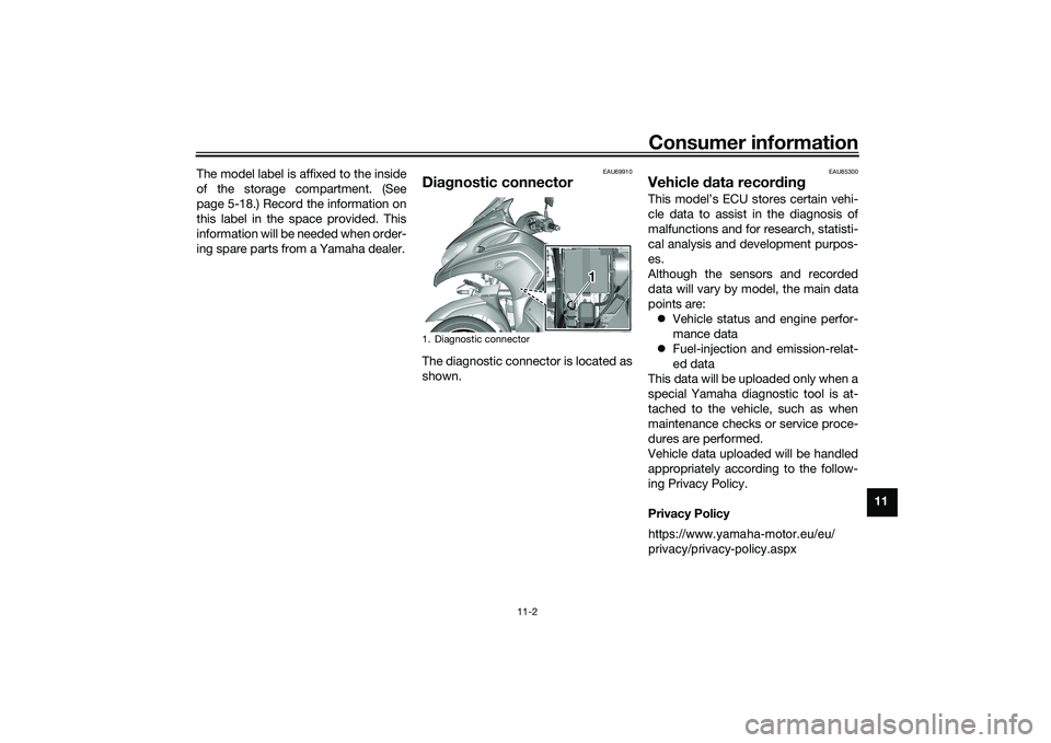
Dia
gnostic connectorThe diagnostic connector is located as
shown.
EAU85300
Vehicle data recor din gThis model’s ECU stores certain vehi-
cle data to assist in the diagnosis of
malfunctions and for research, statisti-
cal analysis and development purpos-
es.
Although the sensors and recorded
data will vary by model, the main data
points are:
Vehicle status and engine perfor-
mance data
Fuel-injection and emission-relat-
ed data
This data will be uploaded only when a
special Yamaha diagnostic tool is at-
tached to the vehicle, such as when
maintenance checks or service proce-
dures are performed.
Vehicle data uploaded will be handled
appropriately according to the follow-
ing Privacy Policy.
Privacy Policy
1. Diagnostic connector
1 1
https://www.yamaha-motor.eu/eu/
privacy/privacy-policy.aspx
UBX9E0E0.book Page 2 Monday, January 20, 2020 10:54 AM