2020 YAMAHA TRICITY 300 Panel
[x] Cancel search: PanelPage 8 of 114

Table of contentsSafety information ............................ 1-1
Further safe-riding points ............... 1-5
Description ....................................... 2-1
Left view ......................................... 2-1
Right view ....................................... 2-2
Controls and instruments ............... 2-3
Smart key system ........................... 3-1
Smart key system ........................... 3-1
Operating range of the smart key system......................................... 3-2
Handling of the smart key and mechanical keys ......................... 3-3
Smart key ....................................... 3-4
Replacing the smart key battery..... 3-6
Main switch .................................... 3-7
Stan din g assist ................................. 4-1
Standing assist ............................... 4-1
Instrument an d control functions ... 5-1
Indicator lights and warning
lights............................................ 5-1
Multi-function meter unit ................ 5-3
Handlebar switches ........................ 5-8
Front brake lever .......................... 5-10
Brake pedal .................................. 5-10
Rear brake lever ........................... 5-11
Parking brake lever ....................... 5-12
ABS .............................................. 5-12 Traction control system ................ 5-13
Fuel tank cap ................................ 5-15
Fuel ............................................... 5-16
Fuel tank overflow hose ................ 5-18
Catalytic converter ........................ 5-18
Storage compartment ................... 5-18
Adjusting the shock absorber
assemblies ................................. 5-20
Auxiliary DC jack ........................... 5-20
Sidestand ...................................... 5-21
Ignition circuit cut-off system ....... 5-22
For your safety – pre-operation
checks ............................................... 6-1
Operation an d important ri din g
points ................................................. 7-1
Engine break-in ............................... 7-1
Starting the engine .......................... 7-2
Starting off ...................................... 7-3
Acceleration and deceleration ........ 7-3
Braking ............................................ 7-3
Tips for reducing fuel consumption ................................ 7-4
Parking ............................................ 7-4
Perio dic maintenance an d
a d justment ........................................ 8-1
Tool kit ............................................ 8-2
Periodic maintenance charts .......... 8-3 Periodic maintenance chart for the
emission control system ............. 8-3
General maintenance and lubrication chart .......................... 8-4
Removing and installing the
panel............................................ 8-9
Checking the spark plug............... 8-10
Canister ........................................ 8-11
Engine oil and oil filter element..... 8-12
Why Yamalube.............................. 8-14
Final transmission oil .................... 8-14
Coolant ......................................... 8-15
Air filter and V-belt case air filter elements .................................... 8-17
Checking the throttle grip free play ............................................ 8-21
Valve clearance............................. 8-21
Tires .............................................. 8-22
Cast wheels .................................. 8-23
Checking the front brake lever
free play..................................... 8-24
Checking the rear brake lever free play..................................... 8-24
Checking the parking brake ......... 8-25
Checking the front and rear brake pads ................................ 8-25
Checking the brake fluid level ...... 8-26
Changing the brake fluid .............. 8-27
Checking the V-belt ...................... 8-27
Checking and lubricating the cables ........................................ 8-28UBX9E0E0.book Page 1 Monday, January 20, 2020 10:54 AM
Page 69 of 114

Periodic maintenance an d a djustment
8-9
8
EAU18752
Removin g an d installin g the
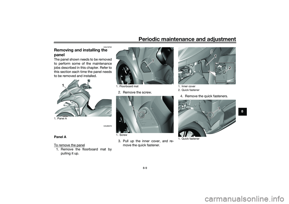
panelThe panel shown needs to be removed
to perform some of the maintenance
jobs described in this chapter. Refer to
this section each time the panel needs
to be removed and installed.
EAU89370
Panel A
To remove the panel1. Remove the floorboard mat by
pulling it up. 2. Remove the screw.
3. Pull up the inner cover, and re-
move the quick fastener. 4. Remove the quick fasteners.1. Panel A
1
1. Floorboard mat
1. Screw
1 1
1 1
1
1. Inner cover
2. Quick fastener
1. Quick fastener
1 1
1
2
2
1 1
1
UBX9E0E0.book Page 9 Monday, January 20, 2020 10:54 AM
Page 70 of 114

Periodic maintenance an d a djustment
8-10
8 5. Pull the panel outward and slide it
rearward as shown.
To install the panel
1. Place the panel in the original po- sition, and then install the quick
fasteners and the Inner cover. 2. Install the screw.
3. Install the floorboard mat.
EAU19623
Checkin
g the spark plu gThe spark plug is an important engine
component, which should be checked
periodically, preferably by a Yamaha
dealer. Since heat and deposits will
cause any spark plug to slowly erode,
it should be removed and checked in
accordance with the periodic mainte-
nance and lubrication chart. In addi-
tion, the condition of the spark plug
can reveal the condition of the engine.
The porcelain insulator around the
center electrode of the spark plug
should be a medium-to-light tan (the
ideal color when the vehicle is ridden
normally). If the spark plug shows a
distinctly different color, the engine
could be operating improperly. Do not
attempt to diagnose such problems
yourself. Instead, have a Yamaha deal-
er check the vehicle.
If the spark plug shows signs of elec-
trode erosion and excessive carbon or
other deposits, it should be replaced.
1. Quick fastener
1. Panel A
1
1
1. Panel A
1
Specified spark plu g:
NGK/LMAR8A-9
UBX9E0E0.book Page 10 Monday, January 20, 2020 10:54 AM
Page 92 of 114

Periodic maintenance an d a djustment
8-32
8
EAU60691
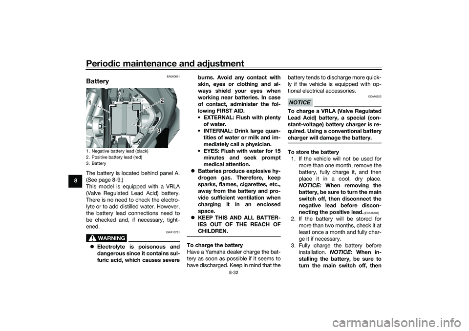
BatteryThe battery is located behind panel A.
(See page 8-9.)
This model is equipped with a VRLA
(Valve Regulated Lead Acid) battery.
There is no need to check the electro-
lyte or to add distilled water. However,
the battery lead connections need to
be checked and, if necessary, tight-
ened.
WARNING
EWA10761
Electrolyte is poisonous an d
d an gerous since it contains sul-
furic aci d, which causes severe b
urns. Avoi d any contact with
skin, eyes or clothin g an d al-
ways shiel d your eyes when
workin g near b atteries. In case
of contact, a dminister the fol-
lowin g FIRST AID.
EXTERNAL: Flush with plenty of water.
INTERNAL: Drink lar ge quan-
tities of water or milk and im-
me diately call a physician.
EYES: Flush with water for 15 minutes an d seek prompt
me dical attention.
Batteries pro duce explosive hy-
d ro gen gas. Therefore, keep
sparks, flames, ci garettes, etc.,
away from the battery an d pro-
vi de sufficient ventilation when
char gin g it in an enclose d
space.
KEEP THIS AND ALL BATTER-
IES OUT OF THE REACH OF
CHILDREN.
To char ge the battery
Have a Yamaha dealer charge the bat-
tery as soon as possible if it seems to
have discharged. Keep in mind that the battery tends to discharge more quick-
ly if the vehicle is equipped with op-
tional electrical accessories.
NOTICE
ECA16522
To char
ge a VRLA (Valve Re gulate d
Lea d Aci d) battery, a special (con-
stant-volta ge) battery char ger is re-
quire d. Usin g a conventional b attery
char ger will damag e the b attery.To store the battery
1. If the vehicle will not be used for more than one month, remove the
battery, fully charge it, and then
place it in a cool, dry place.
NOTICE: When removin g the
b attery, be sure to turn the main
switch off, then disconnect the
ne gative lea d before discon-
nectin g the positive lea d.
[ECA16304]
2. If the battery will be stored for
more than two months, check it at
least once a month and fully char-
ge it if necessary.
3. Fully charge the battery before installation. NOTICE: When in-
stallin g the battery, be sure to
turn the main switch off, then
1. Negative battery lead (black)
2. Positive battery lead (red)
3. Battery1 2
3
UBX9E0E0.book Page 32 Monday, January 20, 2020 10:54 AM
Page 93 of 114
![YAMAHA TRICITY 300 2020 Owners Manual Periodic maintenance an d a djustment
8-33
8
connect the positive lea
d b efore
connectin g the ne gative lea d.
[ECA16842]
4. After installation, make sure that
the battery leads are properly con-
ne YAMAHA TRICITY 300 2020 Owners Manual Periodic maintenance an d a djustment
8-33
8
connect the positive lea
d b efore
connectin g the ne gative lea d.
[ECA16842]
4. After installation, make sure that
the battery leads are properly con-
ne](/manual-img/51/51928/w960_51928-92.png)
Periodic maintenance an d a djustment
8-33
8
connect the positive lea
d b efore
connectin g the ne gative lea d.
[ECA16842]
4. After installation, make sure that
the battery leads are properly con-
nected to the battery terminals.NOTICE
ECA16531
Always keep the b attery charged .
Storin g a dischar ged battery can
cause permanent battery damag e.
EAU89081
Replacin g the fusesThe main fuse and the fuse boxes,
which contain the fuses for the individ-
ual circuits, are located behind panel A.
(See page 8-9.)TIPTo access the main fuse, remove the
starter relay cover as shown.1. Starter relay cover
2. Spare main fuse
3. Main fuse
2 2
3 2
3
1
1. Backup fuse
2. Radiator fan motor fuse
3. Ignition fuse
4. ABS control unit fuse
5. Signaling system fuse
6. Grip warmer fuse
7. Spare fuse
8. Headlight fuse
9. ABS motor fuse
10.ABS solenoid fuse
11.Hazard fuse
12.Auxiliary DC jack fuse
13.Answer back fuse
14.Standing assist battery fuse
15.Standing assist fuse
14157
910111213
7
123465
7
8
UBX9E0E0.book Page 33 Monday, January 20, 2020 10:54 AM
Page 103 of 114

Vehicle care and stora ge
9-2
9
chemicals such as, solvents,
g
asoline, rust removers, b rake
flui d, or antifreeze, etc.
Before washin g
1. Park the vehicle out of direct sun- light and allow it to cool. This will
help avoid water spots.
2. Make sure all caps, covers, elec- trical couplers and connectors are
tightly installed.
3. Cover the muffler end with a plas- tic bag and a strong rubber band.
4. Pre-soak stubborn stains like in- sects or bird droppings with a wet
towel for a few minutes.
5. Remove road grime and oil stains with a quality degreasing agent
and a plastic-bristle brush or
sponge. NOTICE: Do not use
d eg reasin g a gent on areas re-
quirin g lu brication such as
seals, gaskets, an d wheel axles.
Follow pro duct instructions.
[ECA26290]
Washin g
1. Rinse off any degreaser and spray down the vehicle with a garden
hose. Use only enough pressure
to do the job. Avoid spraying wa-
ter directly into the muffler, instru-
ment panel, air inlet, or other inner
areas such as underseat storage
compartments.
2. Wash the vehicle with a quality au- tomotive-type detergent mixed
with cool water and a soft, clean
towel or sponge. Use an old tooth-
brush or plastic-bristle brush for
hard-to-reach places. NOTICE:
Use col d water if the vehicle has
b een exposed to salt. Warm wa-
ter will increase salt’s corrosive
properties.
[ECA26301]
3. For windshield-equipped vehicles: Clean the windshield with a soft
towel or sponge dampened with
water and a pH neutral detergent.
If necessary, use a high-quality
windshield cleaner or polish for
motorcycles. NOTICE: Never use
any stron g chemicals to clean
the wind shield. Additionally,
some cleanin g compoun ds for plastic may scratch the win
d-
shiel d, so b e sure to test all
cleanin g pro ducts before gen-
eral application.
[ECA26310]
4. Rinse off thoroughly with clean water. Be sure to remove all deter-
gent residues, as they can be
harmful to plastic parts.
After washin g
1. Dry the vehicle with a chamois or absorbent towel, preferably mi-
crofiber terrycloth.
2. For drive chain-equipped models: Dry and then lubricate the drive
chain to prevent rust.
3. Use a chrome polish to shine chrome, aluminum, and stainless
steel parts. Often the thermally in-
duced discoloring of stainless
steel exhaust systems can be re-
moved through polishing.
4. Apply a corrosion protection spray on all metal parts including
chrome or nickel-plated surfaces.
WARNING! Do not apply sili- cone or oil spray to seats, han d
g rips, ru bber foot pe gs or tire
trea ds. Otherwise these parts
UBX9E0E0.book Page 2 Monday, January 20, 2020 10:54 AM
Page 111 of 114

12-1
12
Index
AABS....................................................... 5-12
ABS warning light ................................... 5-2
Acceleration and deceleration ................ 7-3
Air filter and V-belt case air filter
elements ............................................. 8-17
Air temperature display .......................... 5-8
Auxiliary DC jack .................................. 5-20BBattery .................................................. 8-32
Brake fluid, changing............................ 8-27
Brake fluid level, checking.................... 8-26
Brake lever, front .................................. 5-10
Brake lever, rear ................................... 5-11
Brake levers, lubricating ....................... 8-28
Brake pedal .......................................... 5-10
Brake pedal, checking and lubricating........................................... 8-29
Braking ................................................... 7-3CCables, checking and lubricating ......... 8-28
Canister ................................................ 8-11
Care ........................................................ 9-1
Catalytic converter ............................... 5-18
Centerstand and sidestand, checking and lubricating ................................... 8-29
Clock ...................................................... 5-4
Coolant ................................................. 8-15
Coolant temperature warning light ......... 5-1DData recording, vehicle......................... 11-2
Diagnostic connector ........................... 11-2
Dimmer/Pass switch............................... 5-9
Display units, switching .......................... 5-3
EEmergency mode ................................. 8-40
Engine break-in ...................................... 7-1
Engine oil and oil filter element ............ 8-12
Engine overheating .............................. 8-39
Engine serial number ........................... 11-1
Engine trouble warning light .................. 5-1FFinal transmission oil............................ 8-14
Front and rear brake pads, checking ... 8-25
Front brake lever free play, checking ... 8-24
Front fork, checking ............................. 8-30
Fuel ...................................................... 5-16
Fuel consumption, tips for reducing ...... 7-4
Fuel meter .............................................. 5-4
Fuel tank cap........................................ 5-15
Fuel tank overflow hose ....................... 5-18
Fuses, replacing ................................... 8-33HHandlebar switches ............................... 5-8
Hazard switch ........................................ 5-9
High beam indicator light ....................... 5-1
Horn switch ............................................ 5-9IIdentification numbers ......................... 11-1
Ignition circuit cut-off system .............. 5-22
Indicator lights and warning lights ......... 5-1KKey, handling of smart and mechanical keys...................................................... 3-3LLicense plate light bulb, replacing ....... 8-36MMain switch ............................................ 3-7 Maintenance and lubrication, periodic ... 8-4
Maintenance, emission control
system .................................................. 8-3
Matte color, caution................................ 9-1
Model label ........................................... 11-1
Multi-function display ............................. 5-5
Multi-function meter unit ........................ 5-3
OOperating range of the smart key system .................................................. 3-2PPanel, removing and installing ................ 8-9
Parking.................................................... 7-4
Parking brake, checking ....................... 8-25
Parking brake indicator light ................... 5-1
Parking brake lever ............................... 5-12
Part locations.......................................... 2-1RRear brake lever free play, checking .... 8-24SSafe-riding points ................................... 1-5
Safety information................................... 1-1
SEL/RES switch ...................................... 5-9
Shock absorber assemblies, adjusting ............................................. 5-20
Sidestand.............................................. 5-21
Smart key................................................ 3-4
Smart key battery, replacing................... 3-6
Smart key system ................................... 3-1
Smart key system indicator light ............ 5-2
Smart key system, troubleshooting ...... 8-37
Spark plug, checking ............................ 8-10
Specifications ....................................... 10-1
Speedometer .......................................... 5-3
UBX9E0E0.book Page 1 Monday, January 20, 2020 10:54 AM