2020 YAMAHA TRICITY 300 wheel
[x] Cancel search: wheelPage 45 of 114
Instrument and control functions
5-14
5
Settin
g the traction control system
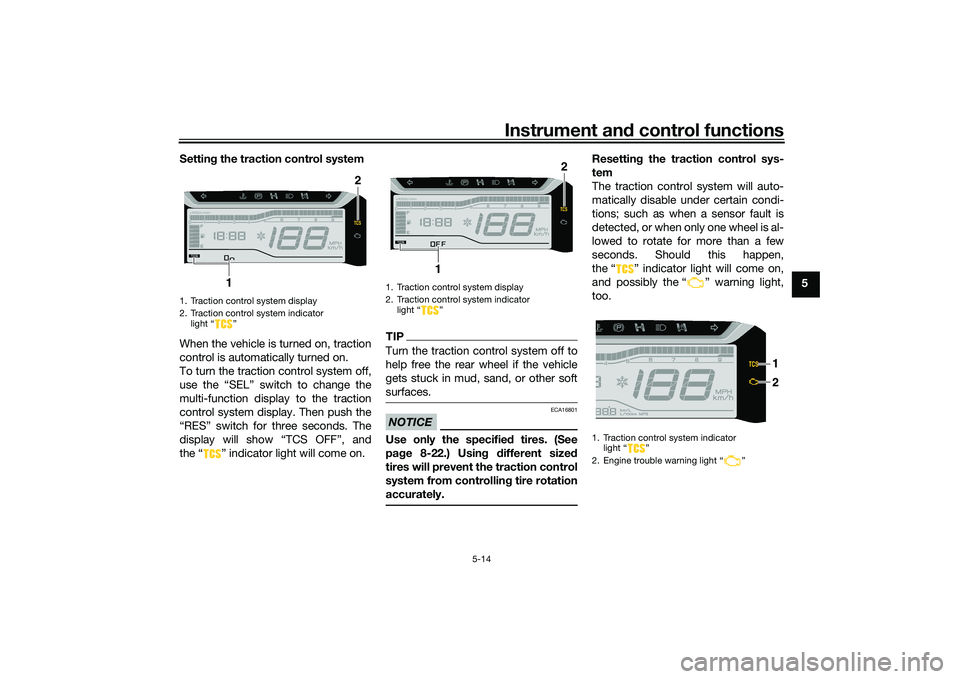
When the vehicle is turned on, traction
control is automatically turned on.
To turn the traction control system off,
use the “SEL” switch to change the
multi-function display to the traction
control system display. Then push the
“RES” switch for three seconds. The
display will show “TCS OFF”, and
the “ ” indicator light will come on.
TIPTurn the traction control system off to
help free the rear wheel if the vehicle
gets stuck in mud, sand, or other soft
surfaces.NOTICE
ECA16801
Use only the specifie d tires. (See
pa ge 8-22.) Usin g different sized
tires will prevent the traction control
system from controllin g tire rotation
accurately.
Resettin g the traction control sys-
tem
The traction control system will auto-
matically disable under certain condi-
tions; such as when a sensor fault is
detected, or when only one wheel is al-
lowed to rotate for more than a few
seconds. Should this happen,
the “ ” indicator light will come on,
and possibly the “ ” warning light,
too.
1. Traction control system display
2. Traction control system indicator light “ ”
2
1
1. Traction control system display
2. Traction control system indicator light “ ”
2
1
1. Traction control system indicator light “ ”
2. Engine trouble warning light “ ”
2 1
UBX9E0E0.book Page 14 Monday, January 20, 2020 10:54 AM
Page 56 of 114
For your safety – pre-operation checks
6-2
6
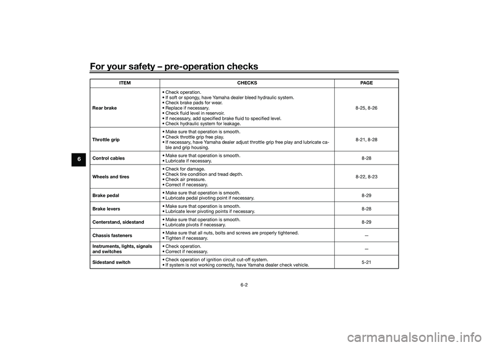
Rear brake • Check operation.
• If soft or spongy, have Yamaha dealer bleed hydraulic system.
• Check brake pads for wear.
• Replace if necessary.
• Check fluid level in reservoir.
• If necessary, add specified brake fluid to specified level.
• Check hydraulic system for leakage. 8-25, 8-26
Throttle g rip • Make sure that operation is smooth.
• Check throttle grip free play.
• If necessary, have Yamaha dealer adjust throttle grip free play and lubricate ca-
ble and grip housing. 8-21, 8-28
Control ca bles • Make sure that operation is smooth.
• Lubricate if necessary. 8-28
Wheels an d tires •Check for damage.
• Check tire condition and tread depth.
• Check air pressure.
• Correct if necessary. 8-22, 8-23
Brake ped al • Make sure that operation is smooth.
• Lubricate pedal pivoting point if necessary.
8-29
Brake levers • Make sure that operation is smooth.
• Lubricate lever pivoting points if necessary.
8-28
Centerstan d, si destan d • Make sure that operation is smooth.
• Lubricate pivots if necessary. 8-29
Chassis fasteners • Make sure that all nuts, bolts and screws are properly tightened.
• Tighten if necessary.
—
Instruments, li ghts, si gnals
an d switches • Check operation.
• Correct if necessary.
—
Si destan d switch • Check operation of ignition circuit cut-off system.
• If system is not working correctly, have Yamaha dealer check vehicle. 5-21
ITEM
CHECKS PAGE
UBX9E0E0.book Page 2 Monday, January 20, 2020 10:54 AM
Page 65 of 114
Periodic maintenance an d a djustment
8-5
8
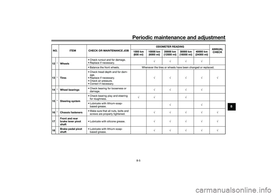
12 *Wheels • Check runout and for damage.
• Replace if necessary.
√√√√
• Balance the front wheels. Whenever the tires or wheels have been changed or replaced.
13 *Tires • Check tread depth and for dam-
age.
• Replace if necessary.
• Check air pressure.
• Correct if necessary. √√√√√
14 *Wheel bearin gs • Check bearing for looseness or
damage. √√√√
15 *Steerin g system • Check bearing play and steering
for roughness. √√ √
• Lubricate with lithium-soap- based grease. √√
16 *Chassis fasteners • Make sure that all nuts, bolts and
screws are properly tightened. √√√√√
17 Front an
d rear
b rake lever pivot
shaft • Lubricate with silicone grease.
√√√√√
18 Brake ped
al pivot
shaft • Lubricate with lithium-soap-
based grease. √√√√√
NO. ITEM CHECK OR MAINTENANCE JOB
ODOMETER READING
ANNUAL
CHECK
1000 km
(600 mi) 10000 km
(6000 mi) 20000 km
(12000 mi) 30000 km
(18000 mi) 40000 km
(24000 mi)
UBX9E0E0.book Page 5 Monday, January 20, 2020 10:54 AM
Page 75 of 114
Periodic maintenance an d a djustment
8-15
8
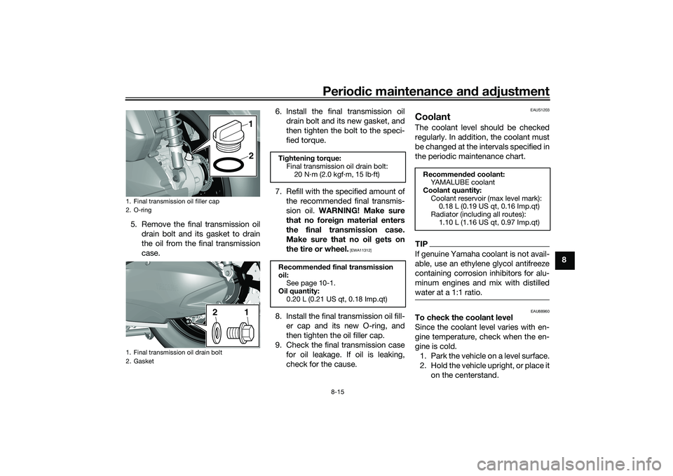
5. Remove the final transmission oil
drain bolt and its gasket to drain
the oil from the final transmission
case. 6. Install the final transmission oil
drain bolt and its new gasket, and
then tighten the bolt to the speci-
fied torque.
7. Refill with the specified amount of the recommended final transmis-
sion oil. WARNING! Make sure
that no forei gn material enters
the final transmission case.
Make sure that no oil gets on
the tire or wheel.
[EWA11312]
8. Install the final transmission oil fill- er cap and its new O-ring, and
then tighten the oil filler cap.
9. Check the final transmission case for oil leakage. If oil is leaking,
check for the cause.
EAUS1203
CoolantThe coolant level should be checked
regularly. In addition, the coolant must
be changed at the intervals specified in
the periodic maintenance chart.TIPIf genuine Yamaha coolant is not avail-
able, use an ethylene glycol antifreeze
containing corrosion inhibitors for alu-
minum engines and mix with distilled
water at a 1:1 ratio.
EAU88960
To check the coolant level
Since the coolant level varies with en-
gine temperature, check when the en-
gine is cold.1. Park the vehicle on a level surface.
2. Hold the vehicle upright, or place it on the centerstand.
1. Final transmission oil filler cap
2. O-ring
1. Final transmission oil drain bolt
2. Gasket
1
21
2
Ti ghtenin g torque:
Final transmission oil drain bolt: 20 N·m (2.0 kgf·m, 15 lb·ft)
Recommen ded final transmission
oil: See page 10-1.
Oil quantity: 0.20 L (0.21 US qt, 0.18 Imp.qt)
Recommen ded coolant:
YAMALUBE coolant
Coolant quantity: Coolant reservoir (max level mark): 0.18 L (0.19 US qt, 0.16 Imp.qt)
Radiator (including all routes): 1.10 L (1.16 US qt, 0.97 Imp.qt)
UBX9E0E0.book Page 15 Monday, January 20, 2020 10:54 AM
Page 79 of 114
Periodic maintenance an d a djustment
8-19
8
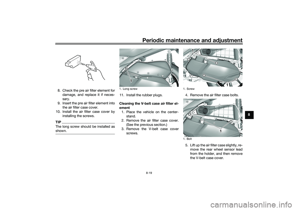
8. Check the pre air filter element for
damage, and replace it if neces-
sary.
9. Insert the pre air filter element into the air filter case cover.
10. Install the air filter case cover by installing the screws.
TIPThe long screw should be installed as
shown.
11. Install the rubber plugs.
Cleanin g the V- belt case air filter el-
ement 1. Place the vehicle on the center- stand.
2. Remove the air filter case cover. (See the previous section.)
3. Remove the V-belt case cover screws. 4. Remove the air filter case bolts.
5. Lift up the air filter case slightly, re-
move the rear wheel sensor lead
from the holder, and then remove
the V-belt case cover.1. Long screw
1
1. Screw
1. Bolt
1
1
1
UBX9E0E0.book Page 19 Monday, January 20, 2020 10:54 AM
Page 80 of 114
Periodic maintenance an d a djustment
8-20
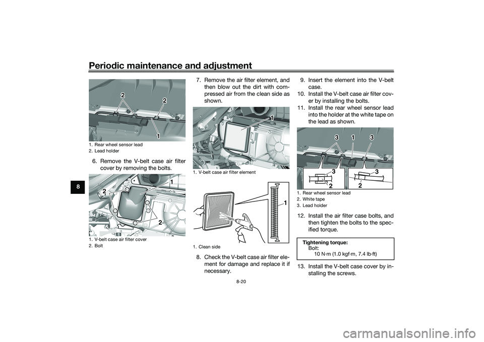
8 6. Remove the V-belt case air filter
cover by removing the bolts. 7. Remove the air filter element, and
then blow out the dirt with com-
pressed air from the clean side as
shown.
8. Check the V-belt case air filter ele- ment for damage and replace it if
necessary. 9. Insert the element into the V-belt
case.
10. Install the V-belt case air filter cov- er by installing the bolts.
11. Install the rear wheel sensor lead into the holder at the white tape on
the lead as shown.
12. Install the air filter case bolts, and then tighten the bolts to the spec-
ified torque.
13. Install the V-belt case cover by in- stalling the screws.
1. Rear wheel sensor lead
2. Lead holder
1. V-belt case air filter cover
2. Bolt
1
2
2
2
2
1
1. V-belt case air filter element
1. Clean side
1
1
1. Rear wheel sensor lead
2. White tape
3. Lead holderTi
ghtenin g torque:
Bolt:
10 N·m (1.0 kgf·m, 7.4 lb·ft)
1
3
3
2
33
2
UBX9E0E0.book Page 20 Monday, January 20, 2020 10:54 AM
Page 83 of 114

Periodic maintenance an d a djustment
8-23
8
WARNING
EWA10472
Have a Yamaha d ealer replace
excessively worn tires. Besid es
b ein g ille gal, operatin g the vehi-
cle with excessively worn tires
d ecreases ri din g sta bility an d
can lead to loss of control.
The replacement of all wheel
and b rake-relate d parts, inclu d-
in g the tires, shoul d b e left to a
Yamaha dealer, who has the
necessary professional knowl-
e dge an d experience to do so.
Ride at mo derate spee ds after
chan gin g a tire since the tire
surface must first be “ broken
in” for it to develop its optimal
characteristics.Tire information
This model is equipped with tubeless
tires and rubber tire air valves.
Tires age, even if they have not been
used or have only been used occasion-
ally. Cracking of the tread and sidewall
rubber, sometimes accompanied by
carcass deformation, is an evidence of ageing. Old and aged tires shall be
checked by tire specialists to ascertain
their suitability for further use.
WARNING
EWA10462
The front an
d rear tires shoul d b e of
the same make an d d esi gn, other-
wise the han dlin g characteristics of
the vehicle may be different, which
coul d lea d to an acci dent.After extensive tests, only the tires list-
ed below have been approved for this
model by Yamaha.
EAU61160
Cast wheelsTo maximize the performance, durabil-
ity, and safe operation of your vehicle,
note the following points regarding the
specified wheels.
The wheel rims should be
checked for cracks, bends, warp-
age or other damage before each
ride. If any damage is found, have
a Yamaha dealer replace the
wheel. Do not attempt even the
smallest repair to the wheel. A de-
formed or cracked wheel must be
replaced.
The front wheels should be bal-
anced whenever either the tires or
wheels have been changed or re-
placed. An unbalanced wheel can
result in poor performance, ad-
verse handling characteristics,
and a shortened tire life.
Front tire:
Size:120/70-14M/C 55P
Manufacturer/model: BRIDGESTONE/BATTLAX SCF
Rear tire:
Size:140/70-14M/C 62P
Manufacturer/model:
BRIDGESTONE/BATTLAX SCR
UBX9E0E0.book Page 23 Monday, January 20, 2020 10:54 AM
Page 85 of 114
Periodic maintenance an d a djustment
8-25
8
EAU89061
Checkin g the parkin g b rakeThe parking brake must be checked
and adjusted at the intervals specified
in the periodic maintenance and lubri-
cation chart, or sooner if the parking
brake does not properly hold the
wheel.
EAU22393
Checkin g the front an d rear
b rake pa dsThe front and rear brake pads must be
checked for wear at the intervals spec-
ified in the periodic maintenance and
lubrication chart.
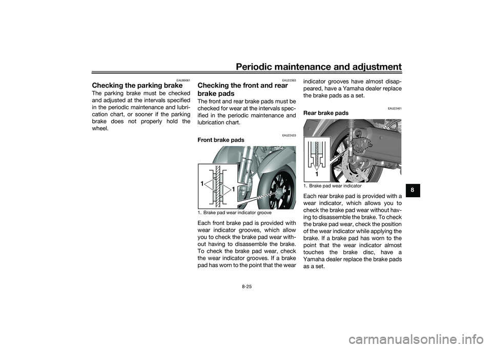
EAU22433
Front brake pad s
Each front brake pad is provided with
wear indicator grooves, which allow
you to check the brake pad wear with-
out having to disassemble the brake.
To check the brake pad wear, check
the wear indicator grooves. If a brake
pad has worn to the point that the wear indicator grooves have almost disap-
peared, have a Yamaha dealer replace
the brake pads as a set.
EAU22461
Rear
brake pa ds
Each rear brake pad is provided with a
wear indicator, which allows you to
check the brake pad wear without hav-
ing to disassemble the brake. To check
the brake pad wear, check the position
of the wear indicator while applying the
brake. If a brake pad has worn to the
point that the wear indicator almost
touches the brake disc, have a
Yamaha dealer replace the brake pads
as a set.
1. Brake pad wear indicator groove1 1
1. Brake pad wear indicator
1
UBX9E0E0.book Page 25 Monday, January 20, 2020 10:54 AM