2020 YAMAHA FJR1300AS warning light
[x] Cancel search: warning lightPage 37 of 122

Instrument and control functions
3-23
3
EAU12461Turn si gnal switch “ / ”
To signal a right-hand turn, push this
switch to “ ”. To signal a left-hand
turn, push this switch to “ ”. When
released, the switch returns to the cen-
ter position. To cancel the turn signal
lights, push the switch in after it has re-
turned to the center position.
EAU12501Horn switch “ ”
Press this switch to sound the horn.
EAU54212Stop/Run/Start switch “ / / ”
To crank the engine with the starter,
set this switch to “ ”, and then push
the switch down towards “ ”. See
page 5-2 for starting instructions prior
to starting the engine.
Set this switch to “ ” to stop the en-
gine in case of an emergency, such as
when the vehicle overturns or when the
throttle cable is stuck.
EAU12735Hazar d switch “ ”
With the key in the “ON” or “ ” posi-
tion, use this switch to turn on the haz-
ard lights (simultaneous flashing of all
turn signal lights).
The hazard lights are used in case of an
emergency or to warn other drivers
when your vehicle is stopped where it
might be a traffic hazard.
NOTICE
ECA10062
Do not use the hazar d lig hts for an
exten ded len gth of time with the en-
g ine not runnin g, otherwise the bat-
tery may dischar ge.
EAU12781Cruise control switches
See page 3-6 for an explanation of the
cruise control system.
EAU54232Menu switch “MENU”
This switch is used to make setting
changes within the multi-function me-
ter unit. (See page 3-9.)
EAU54222Select switch “ / ”
This switch is used to make setting
changes within the multi-function me-
ter unit. (See page 3-9.)
EAU55464Stop mo de switch “ ”
When this switch is pushed, the stop
mode function is activated and the
stop mode indicator light comes on.
Stop mode works via the YCC-S sys-
tem to automatically downshift to 1st
gear when coming to a stop.
If stop mode is turned on and the
transmission is in 2nd or higher gear,
when the rider stops the vehicle the
transmission will automatically shift
down to 1st gear.
TIP
When the stop mode function is acti-
vated, the shift down indicator light will
flash only when the rider attempts to
start off in 2nd gear or higher.
EAU54691Drive mo de switch “MODE”
WARNING
EWA15341
Do not chan ge the D-mod e while the
vehicle is movin g.
UB95E2E0.book Page 23 Tuesday, December 17, 2019 10:29 AM
Page 41 of 122

Instrument and control functions
3-27
3
EAU39542
Brake ped al
The brake pedal is located on the right
side of the vehicle.
This model is equipped with a unified
brake system.
When pressing down on the brake
pedal, the rear brake and a portion of
the front brake are applied. For full
braking performance, apply both the
brake lever and the brake pedal simul-
taneously.
EAU73181
ABS
This model’s anti-lock brake system
(ABS) features a dual electronic control
system, which acts on the front and
rear brakes independently.
Operate the brakes with ABS as you
would conventional brakes. If the ABS
is activated, a pulsating sensation may
be felt at the brake lever or brake ped-
al. In this situation, continue to apply
the brakes and let the ABS work; do
not “pump” the brakes as this will re-
duce braking effectiveness.
WARNING
EWA16051
Always keep a sufficient distance
from the vehicle ahea d to match the
ri din g speed even with ABS.
The ABS performs best with
lon g b rakin g d istances.
On certain surfaces, such as
roug h or g ravel roa ds, the b rak-
in g d istance may be lon ger with
the ABS than without.
The ABS is monitored by an ECU,
which will revert the system to conven-
tional braking if a malfunction occurs.
TIP
The ABS performs a self-diagno-
sis test each time the vehicle first
starts off after the key is turned to
“ON” and the vehicle has traveled
at a speed of 10 km/h (6 mi/h) or
higher. During this test, a “click-
ing” noise may be heard from the
hydraulic control unit, and if the
brake lever or brake pedal is even
slightly applied, a vibration can be
felt at the lever and pedal, but this
does not indicate a malfunction.
1. Brake pedal
1
UB95E2E0.book Page 27 Tuesday, December 17, 2019 10:29 AM
Page 42 of 122

Instrument and control functions
3-28
3
This ABS has a test mode which
allows the owner to experience
the pulsation at the brake lever or
brake pedal when the ABS is op-
erating. However, special tools are
required, so please consult your
Yamaha dealer.
NOTICE
ECA16831
Keep any type of mag nets (including
ma gnetic pick-up tools, mag netic
screw drivers, etc.) away from the
front an d rear wheel hu bs; other-
wise, the ma gnetic rotors equippe d
in the wheel hu bs may be damag ed ,
resultin g in improper performance
of the ABS an d the unifie d b rake
system.
EAU54275
Traction control system
The traction control system helps
maintain traction when accelerating on
slippery surfaces, such as unpaved or
wet roads. If sensors detect that the
rear wheel is starting to slip (uncon-
trolled spinning), the traction control
system assists by reducing engine
power until traction is restored.
TIP
The TCS indicator light will flash to
let you know that traction control
has engaged.
Slight changes in engine and ex-
haust sound may also be notice-
able.
WARNING
EWA15433
The traction control system is not a
substitute for ri din g appropriately
for the con ditions. Traction control
cannot prevent loss of traction due
to excessive speed when entering
turns, when acceleratin g har d at a
sharp lean an gle, or while b raking,
an d cannot prevent front wheel slip-
pin g. As with any vehicle, approach
surfaces that may b e slippery with
caution an d avoi d especially slip-
pery surfaces.
1. Front wheel hub
1. Rear wheel hub
1
1
UB95E2E0.book Page 28 Tuesday, December 17, 2019 10:29 AM
Page 43 of 122

Instrument and control functions
3-29
3
Turnin
g TCS off or on
When the vehicle is turned on, the trac-
tion control system automatically turns
on.
To turn off the traction control system,
stop the vehicle and push the traction
control system button for 2 seconds.
The TCS indicator light will come on.
To turn traction control back on, push
the TCS button again. The TCS indica-
tor light will turn off.
TIP
Turn off traction control to help free the
rear wheel if stuck in mud, sand, or
other situation.
Notes on usa ge
The traction control system will disable
if: either wheel comes off the
ground.
excessive rear wheel spin is de-
tected.
either wheel is forcibly rotated
(such as when performing mainte-
nance).
TIP
If the traction control system is dis-
abled, both the TCS indicator light and
the engine trouble warning light will
come on.
NOTICE
ECA16801
Use only the specifie d tires. (See
pa ge 6-20.) Usin g different sized
tires will prevent the traction control
system from controllin g tire rotation
accurately.
To reset the traction control system
1. Turn the vehicle off and wait a few seconds.
2. Turn the vehicle on and start the engine.
3. After traveling at least 20 km/h (12 mph), the TCS indicator light
should turn off and the system be
enabled.
4. Have a Yamaha dealer check the vehicle and turn off the engine
trouble warning light.
TIP
If the TCS indicator light or engine trou-
ble warning light remain on after reset-
ting, ride cautiously and have a
Yamaha dealer check the vehicle as soon as possible.
1. “TCS” button
2. Engine trouble warning light “ ”
3. Traction control system indicator light “ ”
132
UB95E2E0.book Page 29 Tuesday, December 17, 2019 10:29 AM
Page 44 of 122

Instrument and control functions
3-30
3
EAU13077
Fuel tank cap
To open the fuel tank cap
Open the fuel tank cap lock cover, in-
sert the key, and then turn it 1/4 turn
clockwise. The lock will be released
and the fuel tank cap can be opened.
To close the fuel tank cap
With the key still inserted, push down
the fuel tank cap. Turn the key 1/4 turn
counterclockwise, remove it, and then
close the lock cover.
TIP
The fuel tank cap cannot be closed un-
less the key is in the lock. In addition,
the key cannot be removed if the cap is
not properly closed and locked.
WARNING
EWA11092
Make sure that the fuel tank cap is
properly close d after fillin g fuel.
Leakin g fuel is a fire hazar d.
EAU13222
Fuel
Make sure there is sufficient gasoline in
the tank.
WARNING
EWA10882
Gasoline an d gasoline vapors are
extremely flammab le. To avoid fires
an d explosions an d to re duce the
risk of injury when refueling , follow
these instructions.
1. Before refueling, turn off the en- gine and be sure that no one is sit-
ting on the vehicle. Never refuel
while smoking, or while in the vi-
cinity of sparks, open flames, or
other sources of ignition such as
the pilot lights of water heaters
and clothes dryers.
2. Do not overfill the fuel tank. When refueling, be sure to insert the
pump nozzle into the fuel tank filler
hole. Stop filling when the fuel
reaches the bottom of the filler
tube. Because fuel expands when
it heats up, heat from the engine or
the sun can cause fuel to spill out
of the fuel tank.1. Fuel tank cap lock cover
2. Unlock.
1
2
1. Fuel tank filler tube
2. Maximum fuel level
21
UB95E2E0.book Page 30 Tuesday, December 17, 2019 10:29 AM
Page 55 of 122

Instrument and control functions
3-41
3
EAU39672
Rear view mirrors
The rear view mirrors of this vehicle
can be folded forward or backward for
parking in narrow spaces. Fold the mir-
rors back to their original position be-
fore riding.
WARNING
EWA14372
Be sure to fol d the rear view mirrors
b ack to their ori ginal position before
ri din g.
EAU55425
A djustin g the front an d rear
suspension
This model is equipped with an elec-
tronically adjustable suspension sys-
tem. The preload of the rear shock
absorber and the damping forces of
both the front fork and rear shock ab-
sorber can be adjusted.
WARNING
EWA12423
Be sure to stop the vehicle before
makin g any settin g chan ges to the
multi-function meter unit. Chang ing
settin gs while ri din g can d istract the
operator an d increase the risk of an
acci dent.
Preloa d
When riding with luggage or a passen-
ger, use the preload adjusting function
to adjust the suspension system to
match the load. There are 4 preload
settings.
TIP
The preload adjusting function will
appear only when the engine is
running.
Changing the preload setting will
also adjust the front and rear sus-
pension damping forces accord-
ingly. (See page 3-43.)
About cold temperature opera-
tion:
• When using the preload adjust- ing function, there should be no
weight on the vehicle.
• When using the preload adjust- ing function at ambient temper-
atures near or below 0 °C (32
°F), the suspension system
warning light may come on.
1. Riding position
2. Parking position
2
2
1
2 2
1
UB95E2E0.book Page 41 Tuesday, December 17, 2019 10:29 AM
Page 56 of 122
Instrument and control functions
3-42
3 • The suspension will still operate
as normal, only the preload ad-
justing function cannot be used.
• To reset the suspension system warning light, wait approximate-
ly 6 minutes and then turn the
main switch off or immediately
turn the main switch off and
then wait 6 minutes.
• If the suspension system warn- ing light remains on, have a
Yamaha dealer check the vehi- cle.
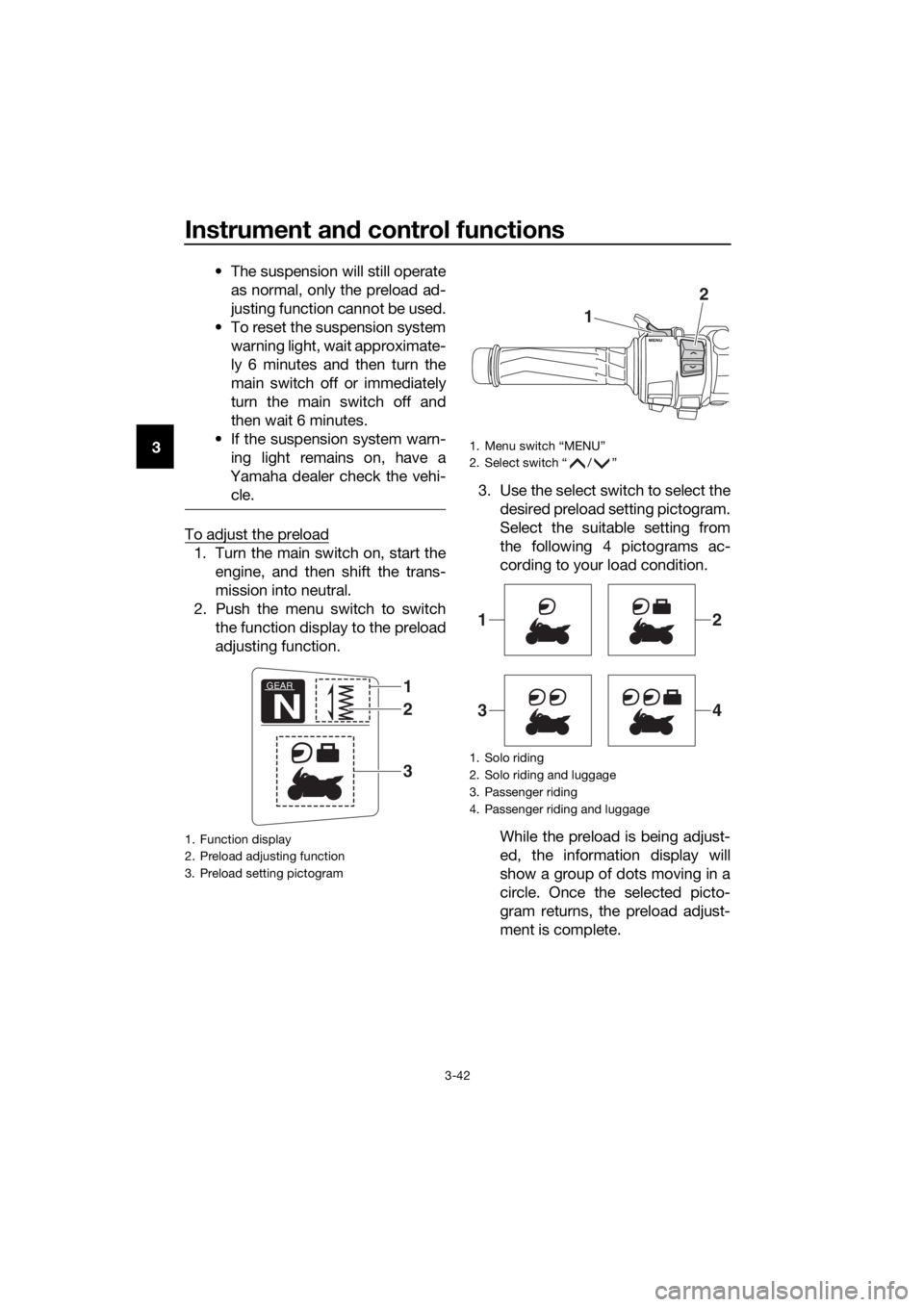
To adjust the preload
1. Turn the main switch on, start the engine, and then shift the trans-
mission into neutral.
2. Push the menu switch to switch the function display to the preload
adjusting function. 3. Use the select switch to select the
desired preload setting pictogram.
Select the suitable setting from
the following 4 pictograms ac-
cording to your load condition.
While the preload is being adjust-
ed, the information display will
show a group of dots moving in a
circle. Once the selected picto-
gram returns, the preload adjust-
ment is complete.
1. Function display
2. Preload adjusting function
3. Preload setting pictogram
GEAR
N
1
3
2
1. Menu switch “MENU”
2. Select switch “ / ”
1. Solo riding
2. Solo riding and luggage
3. Passenger riding
4. Passenger riding and luggage
1
2
12
34
UB95E2E0.book Page 42 Tuesday, December 17, 2019 10:29 AM
Page 62 of 122

Instrument and control functions
3-48
3
With the engine turned off:
1. Place vehicle on centerstand.
2. Move the sidestand down.
3. Set engine stop switch to run position.
4. Turn main switch to on position.
5. Shift transmission into neutral.
6. Apply the front or rear brake.
7. Push the start switch.
Does the engine start?
With the engine still running:
8. Move the sidestand up.
9. Apply the rear brake (to prevent a
TCS error).
10. Shift transmission into gear.
11. Move the sidestand down.
Does the engine stall?
After the engine has stalled:
12. Move the sidestand up.
13. Release the brake.
14. Push the start switch.
Does the engine start?
The system is OK. The motorcycle can
be ridden.
The neutral switch, a brake light switch
or the YCC-S system may not be
working.
The motorcycle should not be ridden
until checked by a Yamaha dealer.
The sidestand switch may not be
working.
The motorcycle should not be ridden
until checked by a Yamaha dealer.
A brake light switch may not be working.
The motorcycle should not be ridden
until checked by a Yamaha dealer.
WARNING
The vehicle must be placed on the centerstand during this inspection.
If a malfunction is found, have the vehicle inspected before riding.
YES NO
YESNO
NOYES
UB95E2E0.book Page 48 Tuesday, December 17, 2019 10:29 AM