2020 VOLVO S90 length
[x] Cancel search: lengthPage 190 of 643

SEATS AND STEERING WHEEL
* Option/accessory.
188
Adjusting * front seat cushion
length Depending on the selected equipment level, the length of the seat cushion can either be adjusted using the multifunction control * on
the side of the seat cushion, or manually adjusted using the control on the front of theseat cushion.
Adjusting seat cushion length using the multifunction control
The multifunction control, located on the side of the seat cushion.
1. Activate the multifunction control by turn-
ing the control
upward/downward. The
seat settings view will appear in the center display. 2.
Select
Cushion extension in the seat set-
tings view.
Push in the front part of the four-way button
to extend the seat cushion.
Press the rear part of the four-way but- ton
to shorten the seat cushion.
Manually adjusting seat cushion length
Control for adjusting seat cushion.
1. Grasp the handle on the front of the
seat and pull upward.
2. Adjust the length of the seat cushion.
3. Release the handle and make sure the seat cushion locks into position.
Related information
Manual front seats (p. 182)
Power
* front seats (p. 183)
Adjusting the power
* front seats (p. 183)
Storing positions for seats, mirrors and head-up display
* (p. 184)
Using stored positions for seats, mirrorsand head-up display
* (p. 185)
Adjusting front seat massage settings
*
(p. 187)
Front seat massage
* settings (p. 186)
Adjusting front seat side bolster settings
*
(p. 189)
Adjusting front seat lumbar support
*
(p. 189)
Adjusting the passenger seat from thedriver's seat
* (p. 191)
Page 191 of 643

SEATS AND STEERING WHEEL
}}
* Option/accessory.189
Adjusting front seat side bolster settings*
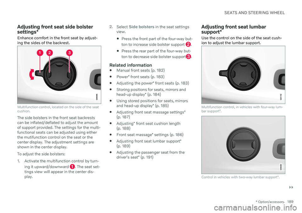
Enhance comfort in the front seat by adjust- ing the sides of the backrest.
Multifunction control, located on the side of the seat cushion.
The side bolsters in the front seat backrests can be inflated/deflated to adjust the amountof support provided. The settings for the multi-functional seats can be adjusted using eitherthe mutifunction control on the seat or thecenter display. The adjustment settings areshown in the center display. To adjust the side bolsters:
1. Activate the multifunction control by turn-
ing it upward/downward
. The seat set-
tings view will appear in the center dis- play. 2.
Select
Side bolsters in the seat settings
view. Press the front part of the four-way but- ton to increase side bolster support
.
Press the rear part of the four-way but- ton to decrease side bolster support
.
Related information
Manual front seats (p. 182)
Power
* front seats (p. 183)
Adjusting the power
* front seats (p. 183)
Storing positions for seats, mirrors and head-up display
* (p. 184)
Using stored positions for seats, mirrorsand head-up display
* (p. 185)
Adjusting front seat massage settings
*
(p. 187)
Adjusting
* front seat cushion length
(p. 188)
Front seat massage
* settings (p. 186)
Adjusting front seat lumbar support
*
(p. 189)
Adjusting the passenger seat from thedriver's seat
* (p. 191)
Adjusting front seat lumbar support *
Use the control on the side of the seat cush- ion to adjust the lumbar support.
Multifunction control, in vehicles with four-way lum- bar support *.
Control in vehicles with two-way lumbar support *.
Page 192 of 643

||
SEATS AND STEERING WHEEL
* Option/accessory.
190 Lumbar support is adjusted using the multi- function control in vehicles with four-way lum- bar support
*, or the round button in vehicles
with two-way lumbar support *. The control is
located on the side of the seat cushion. Depending on the selected equipment level,the lumbar support can be adjusted forward/rearward and up/down (four-way lumbar sup-port) or forward/backward (two-way lumbarsupport).
Adjusting lumbar support in vehicles
with four-way lumbar support
1. Activate the multifunction control by turn-
ing the control
upward/downward. The
seat settings view will appear in the center display. 2.
Select
Lumbar in the seat settings view.
Press the round button up
/down to move the lumbar support upward/ downward.
Press the front part
of the button to
increase lumbar support.
Press the rear part
of the button to
decrease lumbar support.
Adjusting lumbar support in vehicles with two-way lumbar support
1. Press the front part of the round button
to increase lumbar support.
2. Press the rear part
of the round button
to decrease lumbar support.
Related information
Manual front seats (p. 182)
Power
* front seats (p. 183)
Adjusting the power
* front seats (p. 183)
Storing positions for seats, mirrors and head-up display
* (p. 184)
Using stored positions for seats, mirrorsand head-up display
* (p. 185)
Adjusting front seat massage settings
*
(p. 187)
Adjusting
* front seat cushion length
(p. 188)
Front seat massage
* settings (p. 186)
Adjusting front seat side bolster settings
*
(p. 189)
Adjusting the passenger seat from thedriver's seat
* (p. 191)
Page 193 of 643

SEATS AND STEERING WHEEL
* Option/accessory.191
Adjusting the passenger seat from the driver's seat *
The front passenger seat can be adjusted from the driver's seat.
Activating the functionThe function is activated via the function view in the center display:
Tap the
Adjust Passenger
Seat button to activate.
Adjust passenger seatThe driver must adjust the passenger seat within 10 seconds of activating the function. Ifno adjustment is made within this time, thefunction will be deactivated. The driver adjusts the passenger seat using the controls on the driver's seat:
Move the passenger seat forward/rear- ward by moving the control forward/rear-ward.
Change the backrest tilt of the passenger seat by moving the control forward/back-ward.
Related information
Manual front seats (p. 182)
Power
* front seats (p. 183)
Adjusting the power
* front seats (p. 183)
Storing positions for seats, mirrors and head-up display
* (p. 184)
Using stored positions for seats, mirrorsand head-up display
* (p. 185)
Adjusting front seat massage settings
*
(p. 187)
Adjusting
* front seat cushion length
(p. 188)
Front seat massage
* settings (p. 186)
Adjusting front seat side bolster settings
*
(p. 189)
Adjusting front seat lumbar support
*
(p. 189)
Page 431 of 643

STARTING AND DRIVING
* Option/accessory.429
Type approval for HomeLink ®
*22
FCC (USA) and IC (Canada)This device complies with FCC rules part 15 and Industry Canada RSS-210. Operation issubject to the following two conditions: (1)This device may not cause harmful interfer-ence, and (2) This device must accept anyinterference that may be received includinginterference that may cause undesired opera-tion.
WARNING
The transmitter has been tested and com- plies with FCC and IC rules. Changes ormodifications not expressly approved bythe party responsible for compliance couldvoid the user's authority to operate the device.
23
Type approval for EUGentex Corporation hereby declares that HomeLink
®
Model UAHL5 complies with the
Radio equipment directive 2014/53/EU. Wavelengths within which the radio equip- ment operates:
433.05MHz-434.79MHz <10mW E.R.P.
868.00MHz-868.60MHz <25mW E.R.P.
868.70MHz-868.20MHz <25mW E.R.P.
869.40MHz-869.65MHz <25mW E.R.P.
869.70MHz-870.00MHz <25mW E.R.P.
Certificate holder address: Gentex Corpora-tion, 600 North Centennial Street, Zeeland MI49464, USA For further details, search for support informa- tion on type approval at www.volvocars.com.
Related information
HomeLink ®
* (p. 425)
Compass *
An integrated compass 24
in the upper right
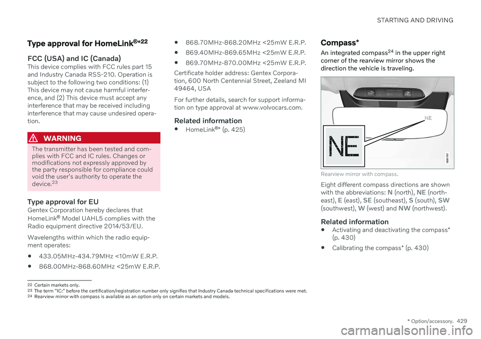
corner of the rearview mirror shows the direction the vehicle is traveling.
Rearview mirror with compass.
Eight different compass directions are shown with the abbreviations: N (north), NE (north-
east), E (east), SE (southeast), S (south), SW(southwest), W (west) and NW (northwest).
Related information
Activating and deactivating the compass
*
(p. 430)
Calibrating the compass
* (p. 430)
22
Certain markets only.
23 The term "IC:" before the certification/registration number only signifies that Industry Canada technical specifications were met.
24 Rearview mirror with compass is available as an option only on certain markets and models.
Page 607 of 643

MAINTENANCE AND SERVICE
}}
605
Sample color code (1): Canadian models.
Exterior color code
Secondary exterior color code (if applica- ble)
Related information
Paintwork (p. 603)
Touching up minor paint damage (p. 603)
Replacing windshield wiper blades
The wiper blades help remove water from the windshield. Along with the washer fluid, theyare designed to clean the glass and helpimprove visibility while driving. The wiperblades can be replaced.Raise the wiper arms to the service posi- tion. Service position is activated/deacti-vated via the function view in the centerdisplay when the car is stationary and thewindshield wipers are not on. Press thebutton on the wiper blade attachment andpull the wiper blade straight out, parallelwith the wiper arm.
Slide in a new wiper blade until it clicks into place.
3. Check to make sure the blade is securely in place.
4. Press the wiper blade back against the windshield.
Wiper blades come in varying lengths
Page 608 of 643

||
MAINTENANCE AND SERVICE
606
NOTE
When changing wiper blades, make sure that the blades are of different lengths. Theblade on the driver's side is longer than theone on the passenger side.
Related information
Using the rain sensor (p. 177)
Using the windshield and headlight wash- ers (p. 178)
Using the rain sensor's memory function(p. 178)
Filling washer fluid (p. 607)
Putting the wiper blades in service posi-tion (p. 606)
Using the windshield wipers (p. 176)
Wiper blades and washer fluid (p. 176)
Putting the wiper blades in service position The windshield wiper blades must be in the service (vertical) position for certain opera-tions, e.g. replacing the blades.
Windshield wipers in the service position.
The windshield wipers must be in the service position when replacing, washing or lifting theblades (e.g. to scrape ice or snow from thewindshield).
CAUTION
Before placing the wipers in service posi- tion, ensure that they have not frozen tothe windshield.
Activating/deactivating service position
The service position can be activated/deacti- vated when the vehicle is stationary and thewindshield wipers are switched off. Serviceposition is activated/deactivated via Functionview in the center display:
Tap the
Wiper Service
Position button. The indica-
tor light in the button will illu- minate when service positionis activated. The wipers willmove to the service positionwhen activated. To deactivate
the service position, tap
Wiper Service
Position once. The indicator light in the but-
ton will go out when service position is deacti- vated.
Page 615 of 643

SPECIFICATIONS
}}
613
DimensionsThe vehicle's length, height, etc. are shown in the table.
Dimensions mm inches
A Ground clearance A
141 5.6
B Wheelbase 3061 120.5 C Length 5083 200.1
D Load length, floor, folded backrest 2098 82.6
E Load length, floor 1149 45.2 F Height B
1450 57.1Dimensions mm inches
G Load height 435 17.1 H Wheel track, front 1628C
1618 D
1617 E64.1
C
63.7 D
63.7 E
I Wheel track, rear 1629C
1619 D
1618 E64.1
C
63.7 D
63.7 EDimensions mm inches
J Load width, floor 1014 39.9
K Width 1879F
1890 G74.0
F
74.4 G