2020 TOYOTA PROACE CITY VERSO ECU
[x] Cancel search: ECUPage 93 of 272

93
Safety
5
IL Seat suitable for an ISOFIX Semi-Universal child seat, which may be eit\
her:– rearward-facing, fitted with an upper strap or a support leg.– forward-facing, fitted with a support leg.– a carrycot fitted with an upper strap or a support leg.For more information on ISOFIX child seats and in particular on securing the upper strap, refer to the correspondi\
ng section.
i-Size child seats
i-Size child seats have two latches that engage on the two rings A.These i-Size child seats also have:– either an upper strap that is attached to ring B.– or a support leg that rests on the vehicle floor, compatible with the approved i-Size seat position.Their role is to prevent the child seat from tipping forward in the even\
t of a collision.For more information on the ISOFIX mountings, refer to the corresponding section.
Locations for i-Size child seats
In accordance with the new European regulations, this table indicates the options for installing i-Size child seats on seats in the vehicle fitted with i-Size approved ISOFIX mountings.
Seat positioni-Size child restraint system
Row 1 (a)Passenger seatNot i-Size
Row 2 (b) (c) (d)i-U
Row 3 (b)Not i-Size
Key
(a) Refer to the current legislation in the country in which you are drivin\
g before placing a child in this seat position.(b) To install a rearward-facing or forward-facing child seat on a rear seat,\
adjust the rear seat to the fully back position with the backrest strai\
ghtened.(c) Adjust the front seat to its maximum height.(d) On some versions, the central seat is not equipped with ISOFIX mounting\
s.i-U Suitable for forward-facing and rearward-facing "Universal" i-Size rest\
raint systems.i-UF Only suitable for forward-facing "Universal" i-Size restraint systems.
Page 107 of 272

107
Driving
6
selector in position P to allow the engine to be started.If position N is selected inadvertently while driving, allow the engine to return to idle, then select position D to accelerate.
WARNI NG
When the engine is running at idle with the brakes released, if position R, D or M is
selected, the vehicle moves even without the accelerator being pressed.Never leave children unsupervised inside the vehicle.As a safety measure, never leave the vehicle without taking your key or remote control with you, even for a short time.When carrying out maintenance with the engine running, apply the parking brake and select position P.
WARNI NG
With an automatic gearbox, never try to start the engine by pushing the vehicle.
Automatic operation
► Select position D for automatic
changing of the gears.The gearbox then operates in auto-adaptive mode, without any intervention on the part of the
driver. It continuously selects the most suitable gear according to the driving style, the road profile and the load in the vehicle.For maximum acceleration without touching the selector, press the accelerator fully down (kick-down). The gearbox changes down automatically or holds the gear selected until the maximum engine speed is reached.When braking, the gearbox changes down automatically to provide effective engine braking.If the accelerator pedal is sharply released, the gearbox will not shift to a higher gear for safety reasons.
WARNI NG
Never select position N while the vehicle is moving.Never select positions P or R unless the vehicle is completely stationary.
Temporary manual control
of gear changes
You can temporarily assume control of gear changing using the "+" et "-” steering-mounted controls. The gear change request will be executed if the engine speed permits. This function allows you to anticipate certain situations, such as overtaking another vehicle or approaching a bend in the road.
After a few seconds with no inputs via the control paddles, the gearbox reverts to automatic operation.
Creeping (moving without
using the accelerator)
This function facilitates manoeuvring of the vehicle at low speed (when parking, in traffic jams, etc.).When the engine is at idle, with the parking brake released and gear position D, M or R selected, the vehicle begins to creep forward as soon as you take your foot off the brake pedal (even without pressing the accelerator).
WARNI NG
As a safety precaution, never leave the vehicle with the engine running and the doors closed.
Manual operation
► With the selector in position D, press button M to enable 6-speed sequential gear changing.The indicator lamp for the button comes on.► Operate the "+" or "-" steering mounted controls. M appears and the engaged gears are shown in succession on the instrument panel.
Page 116 of 272
11 6
NOTIC E
MaintenanceClean the bumpers and door mirrors and the field of vision of the cameras regularly.When washing your vehicle at high pressure, direct the spray from at least 30 cm (0 ft 11") away from the sensors and cameras.
WARNI NG
MatsThe use of mats not approved by TOYOTA may interfere with the operation of the speed limiter or cruise control.To avoid any risk of jamming the pedals:► ensure that the mat is secured correctly,► never fit one mat on top of another.
NOTIC E
Units of speed
Ensure that the units of speed displayed on the instrument panel (km/h or mph) are those for the country you are driving in.If this is not the case, when the vehicle is stationary, set the display to the required units of speed so that it complies with what is authorised locally.In case of doubt, contact a TOYOTA dealer or a qualified workshop.
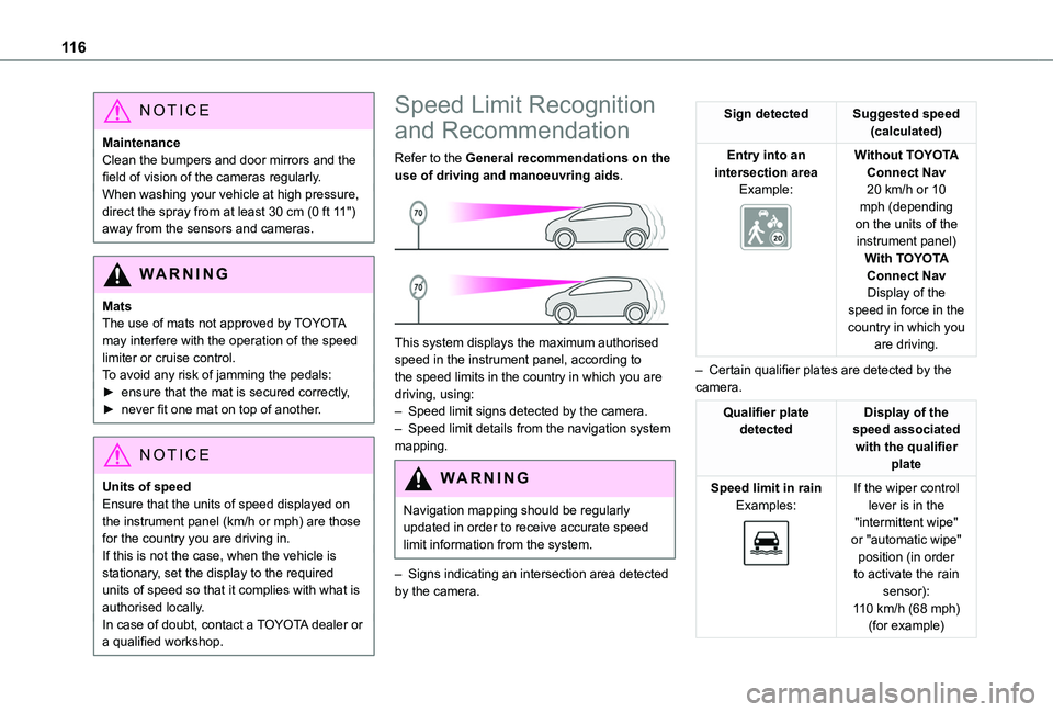
Speed Limit Recognition
and Recommendation
Refer to the General recommendations on the use of driving and manoeuvring aids.
This system displays the maximum authorised speed in the instrument panel, according to the speed limits in the country in which you are driving, using:– Speed limit signs detected by the camera.– Speed limit details from the navigation system mapping.
WARNI NG
Navigation mapping should be regularly updated in order to receive accurate speed limit information from the system.
– Signs indicating an intersection area detected by the camera.
Sign detectedSuggested speed (calculated)
Entry into an intersection areaExample:
Without TOYOTA Connect Nav20 km/h or 10 mph (depending on the units of the instrument panel)With TOYOTA
Connect NavDisplay of the speed in force in the country in which you are driving.
– Certain qualifier plates are detected by the camera.
Qualifier plate detectedDisplay of the speed associated with the qualifier plate
Speed limit in rainExamples:
If the wiper control lever is in the "intermittent wipe" or "automatic wipe" position (in order to activate the rain sensor):
110 km/h (68 mph) (for example)
Page 151 of 272

151
Practical information
7
Towing device with quickly
detachable towball
No tools are required to install or remove this genuine towing device.
NOTIC E
Trailers with LED lamps are not compatible with the wiring harness of this device.
Fitting
► On the towball, move the lever from position 1 to position 2.
► Before fitting the towball, check that the contact points (shown by the arrows) are clean. Use a soft, clean cloth.► Insert the end of the towball into the carrier, located underneath the rear bumper, as far as it can go.► Secure the towball correctly by moving the lever to position 3 ("locked" position).► If necessary, pivot the socket downwards, paying attention to the exhaust pipe.► Connect the trailer plug to the 13-pin socket provided next to the carrier.► Secure the trailer by connecting its safety cable to the eye on the carrier.
Removing
► On the towball, move the lever from position 3 to position 2.► Remove the towball by pulling it towards you.► Once the towball has been removed, move the lever from position 2 to position 1.
WARNI NG
If the towball is not locked, the trailer can detach. This may cause an accident.Always lock the towball as described in the instructions.Observe the legislation in force in the country in which you are driving.Remove the towball when not in use.
Before starting the vehicle, check that the trailer lamps operate correctly.Before setting off, check the adjustment of the headlamp beam height.
WARNI NG
Connect the trailer plug with the engine off.If you connect the trailer plug within a few minutes of switching off the engine, do not
touch the exhaust pipe. Risk of burns!
WARNI NG
Carrier systems (box or bicycle carrier)Always comply with the maximum load authorised on the towing device: if exceeded, the device may detach from the vehicle, potentially causing a serious accident.
NOTIC E
For more information about the Engine technical data and towed loads and in particular, the maximum load on the towing device, refer to the corresponding section.
WARNI NG
Remove the quickly detachable towball when not towing a trailer.
Page 152 of 272

152
Energy economy mode
System which manages the duration of use of certain functions to conserve a sufficient level of charge in the battery.After switching off the engine and for a maximum cumulative period of around 40 minutes, you can continue to use functions such as the audio and telematics system, the wipers, the dipped beam headlamps, the courtesy lamps, etc.
Switching to the mode
A message indicating that the vehicle has switched to economy mode is displayed on the instrument panel screen and the active functions are put on standby.
NOTIC E
If a telephone call is in progress at the time, it will be maintained for around 10 minutes using your audio system’s hands-free system.
Exiting the mode
These functions will be automatically reactivated the next time the vehicle is used.In order to restore the use of these functions immediately, start the engine and let it run:– for less than 10 minutes, to use the equipment for approximately 5 minutes,– for more than 10 minutes, to use the equipment for approximately 30 minutes.
Let the engine run for the duration specified to ensure that the battery charge is sufficient.Do not repeatedly and continuously restart the engine in order to charge the battery.
WARNI NG
A flat battery prevents the engine from starting.For more information on the 12 V battery,
refer to the corresponding section.
Load reduction mode
System that manages the use of certain functions according to the level of charge remaining in the battery.When the vehicle is being driven, the load reduction function temporarily deactivates certain functions, such as the air conditioning and the heated rear screen.The deactivated functions are reactivated automatically as soon as conditions permit.
Roof bars / Roof rack
WARNI NG
RecommendationsDistribute the load uniformly, taking care to avoid overloading one of the sides.
Arrange the heaviest part of the load as close as possible to the roof.Secure the load firmly.Drive gently: the vehicle will be more susceptible to the effects of side winds and its stability may be affected.Regularly check the security and tight fastening of the roof bars and racks, at least before each trip.Remove the roof bars once they are no longer needed.
WARNI NG
In the event of loading (not exceeding 40 cm (1 ft 3") in height) on the roof, do not exceed the following loads:– Transverse bars on longitudinal bars: 80 kg (176 lb).– Two transverse bars bolted to the roof: 100 kg (220 lb).– Three transverse bars bolted to the roof:
150 kg (330 lb).– An aluminium rack: 120 kg (264 lb).– A steel rack: 115 kg (253 lb).If the height exceeds 40 cm (1 ft 3"), adapt the speed of the vehicle to the profile of the road to avoid damaging the roof bars or the roof rack and the fixings on the vehicle.Refer to national legislation in order to comply with the regulations for transporting objects that are longer than the vehicle.
Page 164 of 272
.If p")
164
With spare wheel
5.Wheelbrace.For removing the wheel bolts and raising/lowering the jack.
6.Jack.Used to raise the vehicle.
7.Wheel bolt cover/wheel trim removal tool (depending on equipment).If present on the vehicle, used to remove the wheel bolt covers on alloy wheels or the wheel trim on steel wheels.
8.Socket for the “security” wheel bolts.For adapting the wheelbrace to the special "security" bolts.
NOTIC E
For more information on the Spare wheel, please refer to the corresponding section.
WARNI NG
All of these tools are specific to your vehicle and may vary depending on equipment.Do not use them for any other purposes.
NOTIC E
The jack must only be used to change a
wheel with a damaged or punctured tyre.The jack does not require any maintenance.The jack meets European standards, as defined in the Machinery Directive 2006/42/CE.
NOTIC E
Certain parts of the jack such as the screw thread or the joints could cause injury: avoid touching them.Carefully remove all traces of lubrication grease.
Temporary puncture
repair kit
Comprising a compressor and a sealant
cartridge, it allows the temporary repair of a tyre so that you can drive to the nearest garage.
NOTIC E
It is designed to repair most punctures which could affect the tyre, located on the tyre tread or shoulder.
NOTIC E
The vehicle's electric system allows the connection of the compressor for long enough to inflate a tyre after a puncture repair.
NOTIC E
For more information on the Tool kit, refer to the corresponding section.
Repair procedure
WARNI NG
Do not remove any foreign bodies (e.g. nail, screw) which have penetrated into the tyre.
► Park the vehicle without obstructing traffic and apply the parking brake.► Follow the safety instructions (hazard warning lamps, warning triangle, high visibility vest, etc.) according to the legislation in force in the country of driving.► Switch off the ignition.
Page 165 of 272

165
In the event of a breakdown
8
► Remove the valve cap from the tyre to be repaired, and place it in a clean area.
► Connect the hose from the bottle of sealant to the valve of the tyre to be repaired and tighten firmly.► Connect the pipe from the compressor to the bottle of sealant.► Check that the compressor switch is in position "O".► Fully uncoil the electric cable stowed under the compressor.► Connect the compressor's electric plug to the vehicle's 12 V socket.
WARNI NG
Only the 12 V socket located at the front of the vehicle can be used to power the compressor.
► Affix the speed limit sticker.
WARNI NG
The speed limit sticker must be secured to the interior of the vehicle in the area close to the driver, to remind the driver that a wheel is in temporary use.
NOTIC E
The tyre inflation pressures are given on this label.
► Switch on the ignition.
► Switch on the compressor by moving switch to position "I" until the tyre pressure reaches 2 bars. The sealant product is injected under pressure into the tyre; do not disconnect the pipe from the valve during this operation (risk of blowback).
WARNI NG
If after approximately 7 minutes the pressure of 2 bars is not reached, this indicates that the tyre is not repairable; contact a TOYOTA dealer or a qualified workshop for assistance.
► Move the switch to position "O".► Disconnect the compressor's electric plug from the vehicle's 12 V socket.► Refit the cap on the valve.► Remove the kit.► Remove and store the bottle of sealant.
WARNI NG
The sealant product is harmful if swallowed and causes irritation to the eyes.Keep this product out of the reach of children.The use-by date of the fluid is marked on the bottle.After use, do not discard the bottle in standard waste, take it to a TOYOTA dealer or an authorised waste disposal site.Do not forget to obtain a new bottle of sealant, available from a TOYOTA dealer or a qualified workshop.
Page 168 of 272

168
With an automatic gearbox, select mode P to lock the wheels, apply the parking brake, unless it is programmed to be in automatic mode, and switch off the ignition.Check for the fixed illumination of the parking brake warning lamps in the instrument panel.The occupants must get out of the vehicle and wait where they are safe.If necessary, place a chock under the wheel diagonally opposite the wheel to be changed.Never go underneath a vehicle raised using a jack; use an axle stand.
NOTIC E
Wheel with wheel trimWhen removing the wheel, first remove the wheel trim by pulling at the valve aperture using the wheelbrace.When refitting the wheel, refit the wheel trim, starting by placing its aperture in line with the valve and then pushing it into place
all round its edge with the palm of your hand.
► With a steel wheel, remove the wheel trim using tool 7.► With an alloy wheel, remove the cap from each of the bolts using tool 7.► If the vehicle is so equipped, fit security bolt socket 8 to wheelbrace 5 to slacken the security bolt.► Slacken (without removing) the other wheel bolts using just wheelbrace 5.
NOTIC E
Wheel with wheel trimWhen removing the wheel, first remove the wheel trim by pulling at the valve aperture using the wheelbrace.
► Place the foot of the jack on the ground and ensure that it is directly below the A or B jacking
point provided on the underbody, whichever is closest to the wheel to be changed.