2020 Peugeot Boxer key
[x] Cancel search: keyPage 95 of 196

93
Practical information
7Before each use
Check that the towball is correctly locked,
verifying the follow points:
– the green mark on the wheel is in line with the green mark on the towball,– the wheel is in contact with the towball,– the key lock is closed and the key removed; the wheel can no longer be operated,– the towball must not be able to move in its carrier; test by shaking it with your hand.
During use
Never release the locking system with a
trailer or load carrier on the towball.
Never exceed the maximum authorised
weight for the vehicle (the Gross Vehicle
Weight - GVW), the trailer, or the sum of the
two (the Gross Train Weight - GTW).
Following use
When travelling without a trailer or load on a
towbar-mounted carrier, the towball must be
removed and the protective plug inserted in the
carrier. This measure applies particularly where
the towball might obscure visibility of the number
plate or its lighting.
Fitting the towball
► Below the rear bumper , remove the protective plug from the carrier.► Insert the end of towball 4 into carrier 1 and
push it upwards; the locking will take place
automatically.
The wheel 5 turns a quarter of a turn anti-
clockwise; take care to keep your hands clear.
► Check that the mechanism has correctly locked into place (position A).► Close lock 6 using the key.
► Always remove the key . The key cannot be removed when the lock is open.► Clip the cap onto the lock.
► Remove the protective cover from the towball.► Attach the trailer to the towball.► Attach the cable on the trailer to safety eye 3
on the carrier.
► Connect the trailer plug to connection socket 2 on the carrier.
Removing the towball
► Disconnect the trailer plug from the connection socket 2 on the carrier.► Detach the cable on the trailer from the safety eye 3 on the carrier.► Detach the trailer from the towball.► Refit the protective cover to the towball.► Remove the cap from the lock and press it onto the head of the key.► Insert the key into lock 6.
Page 96 of 196

94
Practical information
► Pull the control located on the side of the dashboard towards you.
On the outside
► Open the lock using the key .► Hold towball 4 firmly in one hand; using
the other hand, pull and turn wheel 5 fully in a
clockwise direction; do not release the wheel.
► Extract the towball from the bottom of its carrier 1.► Release the wheel; this automatically stops in the unlocked position (position B).► Refit the protective plug to the carrier .► Carefully stow the towball in its bag away from knocks and dirt.
Maintenance
Correct operation is only possible if the towball
and its carrier are kept clean.
Before cleaning the vehicle with a high-pressure
jet wash, the towball must be removed and the
protective plug fitted to the carrier.
Apply the label provided to a clearly visible area, close to the carrier or in the
boot.
Go to a PEUGEOT dealer or a qualified
workshop for any work on the towbar system.
Roof-mounted carrying
systems
For safety reasons and to avoid damaging the
roof, it is imperative to use a carrying system
(roof bars or roof rack) approved for the vehicle.
Roof bars can only be fitted on H1 or H2 height
versions of vans, combis and minibuses. On
minibuses, check the presence of a roof air
conditioning unit.
The carrying device must be fixed to the
anchorage points on the roof of the vehicle: 6,
8 or 10, depending on the wheelbase of the
vehicle.
Observe the fitting instructions and the
conditions of use in the guide supplied with the
carrying device.
Maximum roof load, evenly distributed:
150 kg, for all versions, within the limits
of the gross vehicle weight (GVW).
Roofs cannot be equipped with a
carrying system on H3 height versions.
Strictly observe the legal provisions in
force concerning the maximum volume
measurements.
For more information on the Technical
data of the vehicle, and in particular on
the dimensions, refer to the corresponding
section.
Bonnet
Opening
Before doing anything under the bonnet,
deactivate the Stop & Start system to
avoid the risk of injury related to an automatic
change to START mode.
On the inside
This operation must only be done with the
vehicle stationary and the driver’s door open.
Page 104 of 196

102
Practical information
If the AdBlue® tank is completely empty
– which is confirmed by the message
"Top up AdBlue: Starting impossible" – it is essential to add at least 5 litres.
After refilling
► Refit the blue cap to the tank filler and turn it clockwise as far as it will go (one sixth of a turn).► Close the fuel filler flap.
Do not dispose of AdBlue® containers in
the household waste.
Place them in a container reserved for this
purpose or take them back to where you
bought them.
Never store AdBlue® containers in your
vehicle.
Precautions for use
AdBlue® is a urea-based solution. This fluid is
non-flammable, colourless and odourless (when
kept in a cool place).
In the event of contact with the skin, wash the
affected area with soap and running water. In the
event of contact with the eyes, immediately rinse
the eyes with large amounts of water or with an
eye wash solution for at least 15 minutes. Seek
medical attention if you feel a persistent burning
sensation or irritation.
If swallowed, immediately wash out the mouth
with clean water and then drink plenty of water.
In certain conditions (high temperature, for
example), the risk of release of ammonia cannot
be excluded: do not inhale the fluid. Ammonia
vapours have an irritant effect on mucous
membranes (eyes, nose and throat).
Store AdBlue® out of the reach of
children, in its original container.
Procedure
Before starting the top-up procedure, ensure that
the vehicle is parked on a flat and level surface.
In wintry conditions, ensure that the temperature
of the vehicle is above -11 °C. Otherwise the AdBlue® may be frozen and so cannot be poured
into its tank. Park the vehicle in a warmer area
for a few hours to allow the top-up to be carried
out.
Never put the AdBlue® into the Diesel
fuel tank.
If any AdBlue® is splashed, or if there are
any spillages on the bodywork, rinse
immediately with cold water or wipe with a
damp cloth.
If the fluid has crystallised, clean it off using a
sponge and hot water.
Important: in the event of a top-up after
an AdBlue breakdown, you must wait
about 5 minutes before switching on the ignition, without opening the driver's door,
unlocking the vehicle or bringing the
electronic key into the passenger
compartment.
Switch on the ignition, then wait for 10
seconds before starting the engine.
► Switch off the ignition and remove the key from the switch to switch off the engine.
► Turn the blue cap of the AdBlue® tank a 6th of
a turn anti-clockwise and remove it.
Filling up
► With a container of AdBlue®: after checking
the expiry date, read the instructions on the
label carefully before pouring the contents of the
container into the vehicle's AdBlue tank.► With an AdBlue® pump: introduce the nozzle
and fill the tank until the nozzle automatically
cuts out.
In order not to overfill the AdBlue® tank:– Add between 10 and 13 litres using AdBlue® containers.– Stop after the nozzle’ s first automatic cut-out, if you are refilling at a service station.
The system only registers AdBlue® top-ups of 5 litres or more.
Page 119 of 196

11 7
In the event of a breakdown
8FusesA (amperes)Allocation
12 7.5Right-hand dipped beam headlamp
13 7.5Left-hand dipped beam headlamp
32 7.5Passenger compartment lighting (+ battery)
34 7.5Minibus passenger compartment lighting - Hazard warning lamps
36 10Audio system - Air conditioning controls - Alarm - Tachograph - Battery cut-off computer - Additional
heating programmer (+ battery)
37 7.5Brake lamps switch - Third brake lamp - Instrument panel (+ key)
38 20Door central locking (+ battery)
42 5ABS sensor and computer - ASR sensor - DSC sensor - Brake lamps switch
43 20Windscreen wiper motor (+ key)
47 20Driver-side electric window motor
48 20Passenger-side electric window motor
49 5Park assist computer - Audio system - Steering-mounted controls - Central and side control pane\
ls -
Auxiliary control panel - Battery cut-off computer (+ key)
50 7.5Airbags and pretensioners computer
51 5Tachograph - Power steering computer - Air conditioning - Reversing lamps - Diesel fuel filter water
sensor - Flowmeter (+ key)
53 7.5Instrument panel (+ battery)
90 7.5Left-hand main beam headlamp
91 7.5Right-hand main beam headlamp
92 7.5Left-hand foglamp
93 7.5Right-hand foglamp
Page 121 of 196

11 9
In the event of a breakdown
8
FusesA (amperes)Allocation
1 40ABS pump supply
2 50Diesel pre-heating unit
3 30Ignition switch - Starter
4 40Diesel heater
5 20/50Passenger compartment ventilation with programmable additional heating (+ battery)
6 40/60
Maximum speed passenger compartment cooling fan unit (+ battery)
740/50/60Minimum speed passenger compartment cooling fan unit (+ battery)
8 40Passenger compartment cooling fan unit (+ key)
9 15Rear 12 V socket (+ battery)
10 15Horn
Page 122 of 196
120
In the event of a breakdown
FusesA (amperes)Allocation
14 15Front 12 V socket (+ battery)
15 15Cigarette lighter (+ battery)
19 7.5Air conditioning compressor
20 30Screenwash/headlamp wash pump
21 15Fuel pump supply
23 30ABS solenoid valves
24 7.5Auxiliary control panel - Door mirror control and folding (+ key)
30 15Door mirror defrosting
12 V battery
Procedure for starting the engine using another
battery or charging a discharged battery.
Lead-acid starter batteries
Batteries contain harmful substances
such as sulphuric acid and lead.
They must be disposed of in accordance
with regulations and must not, in any
circumstances, be discarded with household
waste.
Take used remote control batteries and
vehicle batteries to a special collection point.
Protect your eyes and face before
handling the battery.
All operations on the battery must be carried
out in a well ventilated area and away from
naked flames and sources of sparks, so as to
avoid the risk of explosion or fire.
Wash your hands afterwards.
Accessing the battery
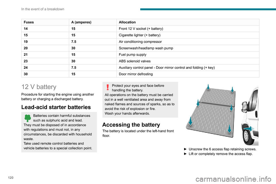
The battery is located under the left-hand front
floor.
► Unscrew the 6 access flap retaining screws.
► Lift or completely remove the access flap.
Page 136 of 196

134
Technical data
Colour
Code
Varnish
B
FOR TROUBLESHOOTING ONLY.
C
DANGER
AUTOMATIC ENGINE STARTING. REMOVE
THE IGNITION KEY WHEN THE BONNET IS
OPEN.
D
1 - WARNING
GENUINE LUBRICANTS AND FLUIDS
Engine oilTransmission
Radiator Brakes
Screenwash Power steering
GENUINE LUBRICANTS AND FLUIDS
CONSULT THE
MAINTENANCE
AND WARRANTY
GUIDE.PROTECT YOUR
EYES.
2 - SAFETY
The use of genuine replacement parts, fluids
and lubricants, as well as observing the servicing
schedules, guarantees the reliability and safety
of your vehicle over time, so maintaining it in its
original condition.
3 - DANGER
KEEP OUT
OF THE
REACH OF
CHILDREN. DO NOT
APPROACH
FLAMES.
DO NOT
TOUCH.
DO NOT
REMOVE
THE CAP
WHEN THE
ENGINE IS
HOT. EXPLOSION.
CORROSIVE
LIQUID.
MAY START
AUTOMATICALLY EVEN
WITH THE ENGINE
SWITCHED OFF. DO NOT
OPEN GAS
UNDER
HIGH
PRESSURE.
AUTOMATIC ENGINE
STARTING. REMOVE THE
IGNITION KEY WHEN THE
BONNET IS OPEN.HIGH
VOLTAGE
In the fuel filler flap
DANGER REMOVE SLOWLY.
FUEL VAPOURS MAY CAUSE INJURY.
On the rear bench seat
A
Push the backrest before folding it down.
B
PULL TO OPEN.
C
PULL LEVER 1 TO PARTIALLY TILT THE
BACKREST.
PULL LEVER 2 TO FOLD THE BACKREST
FULLY.
Page 150 of 196

148
Special features
– Never work under a tipper body that is not supported,– Switch off the power supply to the electro-hydraulic unit using the circuit breaker,– Vehicle stationary, engine off.
For safety reasons, we very strongly
advise against doing anything under the
tipper body while it is being operated or while
it is being serviced.
Maintenance
Reservoir
Regularly check and top up the engine oil level.
Change the oil once a year. If the oil contains
water, change it.
Regularly check the condition of the hose and
ensure the hydraulic system is properly sealed.
Pump and motor
No servicing required. The rolling elements are
permanently lubricated and the bearings are
lubricated by the pumped oil.
Lubrication
The pins of the tipper truck and the ram do not
contain lubricant. Regularly lubricate the hinges
and the grab handles of the side boards as well
as the retaining hooks of the rear board.
Sub-frame and tipper truck
For maximum service life, you are advised to
maintain your tipper truck by regularly washing it
using a power washer.
Carry out any required paint touch-ups quickly to
prevent the spread of rust.
After 8 months of use, check the tightening torque of the connection
between the chassis and the underbody (in
accordance with the manufacturer's
bodybuilding recommendations).
Cleaning the slide valve
► Loosen cap 244A , taking care with the ball
and retrieving it.
► Using a wide screwdriver , unscrew the banjo
bolt/piston assembly.► Check that the piston slides freely and remove any foreign bodies. Use a magnet to
remove any metal filings.
► Refit the assembly and make sure that the piston slides freely. Retain the ball with a little
grease on the cap for refitting.
► Bleed the hydraulic unit.
Bleeding the hydraulic unit
► Unscrew hexagonal cap 257.► Loosen internal screw 587 by half a turn,
using a 6 mm hex key.
► Operate the unit for a few seconds by pressing the raise button.
The tipper truck does not rise or rises very
slowly. When the oil exits through this opening,
the unit is bled.
► Retighten screw 587 and replace cap 257.
Check that the tipper truck lowers correctly.
Detailed diagram of the UD2386 hydraulic unit
Diagnostics
Symptoms ElectricHydraulic Verification/Check
The hydraulic unit does not work. XPower harness and unit relay.
X Control harness (control unit).
X Circuit-breaker.
Very noisy unit, rises slowly. XSuction strainer clogged or crushed at the bottom of the tank.
Very noisy new unit, rises quickly. XPump alignment, change the unit.
The ram lowers by itself. XLowering valve crushed or blocked.
The ram does not lower. XYes, check the slide valve and bleed.
Refer to the "Maintenance" section.
X No, check the coil and the electrical connections of the valve.
X No, replace the solenoid valve.
X No, check the alignment of the ram.
The unit works but its pressure does not increase. XSlide valve jammed if no solenoid valve on the unit.
Refer to the "Maintenance" section.
X Pressure relief device, setting, dirt.
X Pump seal out of service.
X Motor/pump coupling.
X Pump loose from its support.
The hydraulic unit does not work. XSolenoid valve blocked, replace it or retighten the nut behind the
strainer.
The control unit does not work. XCheck connection and contacts.
Emulsion in the tank. XIncorrectly positioned return pipe.
X Insufficient oil level.