2020 PEUGEOT 5008 bonnet
[x] Cancel search: bonnetPage 174 of 308
172
Practical information
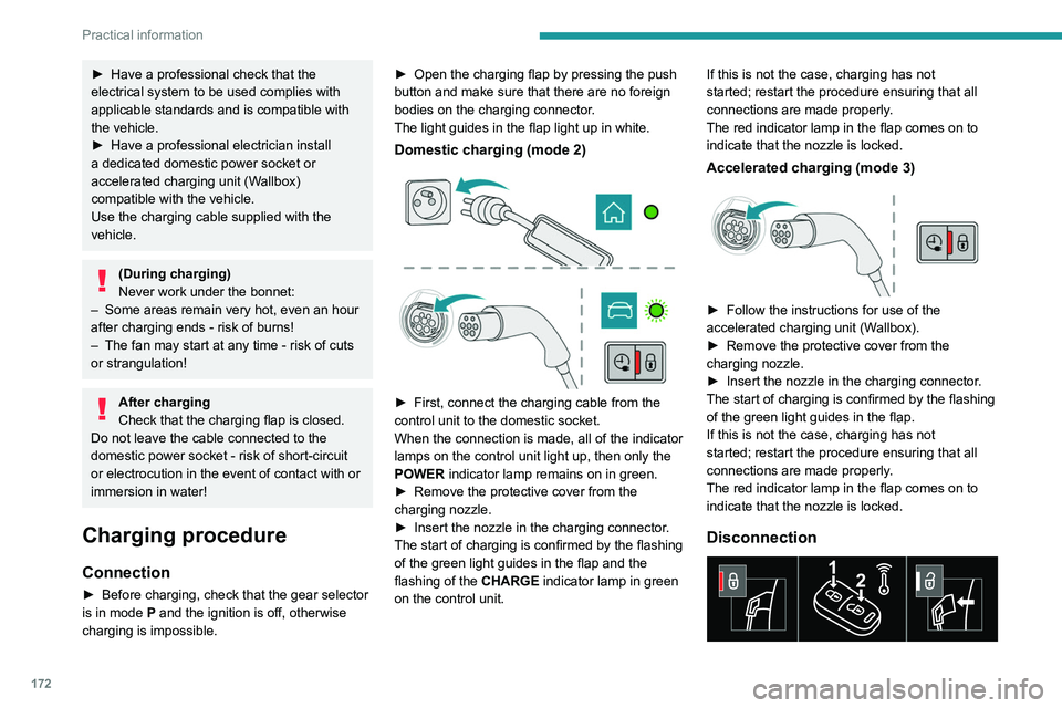
Before disconnecting the nozzle from the
charging connector:
► If the vehicle is unlocked, lock it and then
unlock it .
► If the vehicle is locked, unlock it.
The red indicator lamp in the flap goes out to
confirm that the charging nozzle is unlocked.
► Within 30 seconds, remove the charging
nozzle.
Domestic charging (mode 2)
The end of charging is confirmed by the fixed
lighting of the green CHARGE indicator lamp on
the control unit and by the fixed lighting of the
green light guides in the flap.
► After disconnection, remove the protective
cover from the nozzle and close the charging
flap.
► Disconnect the control unit's charging cable
from the domestic socket.
Accelerated charging (mode 3)
The end of charging is confirmed by the
accelerated charging unit (Wallbox) and by the
fixed lighting of the green light guides in the flap.
► After disconnection, replace the nozzle on the
charging unit and close the charging flap.
Deferred charging
By default, charging begins when the nozzle
is connected. Deferred charging can be
programmed.
► Have a professional check that the
electrical system to be used complies with
applicable standards and is compatible with
the vehicle.
►
Have a professional electrician install
a dedicated domestic power socket or
accelerated charging unit (W
allbox)
compatible with the vehicle.
Use the charging cable supplied with the
vehicle.
(During charging)
Never work under the bonnet:
–
Some areas remain very hot, even an hour
after charging ends - risk of burns!
–
The fan may start at any time - risk of cuts
or strangulation!
After charging
Check that the charging flap is closed.
Do not leave the cable connected to the
domestic power socket - risk of short-circuit
or electrocution in the event of contact with or
immersion in water!
Charging procedure
Connection
► Before charging, check that the gear selector
is in mode P and the ignition is off, otherwise
charging is impossible. ►
Open the charging flap by pressing the push
button and make sure that there are no foreign
bodies on the charging connector
.
The light guides in the flap light up in white.
Domestic charging (mode 2)
► First, connect the charging cable from the
control unit to the domestic socket.
When the connection is made, all of the indicator
lamps on the control unit light up, then only the
POWER
indicator lamp remains on in green.
►
Remove the protective cover from the
charging nozzle.
►
Insert the nozzle in the charging connector
.
The start of charging is confirmed by the flashing
of the green light guides in the flap and the
flashing of the
CHARGE indicator lamp in green
on the control unit. If this is not the case, charging has not
started; restart the procedure ensuring that all
connections are made properly.
The red indicator lamp in the flap comes on to
indicate that the nozzle is locked.
Accelerated charging (mode 3)
► Follow the instructions for use of the
accelerated charging unit (W allbox).
►
Remove the protective cover from the
charging nozzle.
►
Insert the nozzle in the charging connector
.
The start of charging is confirmed by the flashing
of the green light guides in the flap.
If this is not the case, charging has not
started; restart the procedure ensuring that all
connections are made properly.
The red indicator lamp in the flap comes on to
indicate that the nozzle is locked.
Disconnection
Page 181 of 308
179
Practical information
7► Insert a finger into the notch in the upper part
of the screen.
►
Pull towards you to unclip the unit.
Repeat these operations for the other screen.
Energy economy mode
This system manages the duration of use of
certain functions, in order to conserve a sufficient
level of charge in the battery with the ignition off.
After switching off the engine, you can still
use functions such as the audio and telematic
system, the wipers and the dipped beam
headlamps or courtesy lamps, for a combined
duration of approximately 40 minutes.
Selecting the mode
A confirmation message is displayed when
energy economy mode is entered, and the active
functions are placed on standby.
If a telephone call is in progress at the
time, it will be maintained for around 10
minutes via the audio system’s hands-free
system.
Exiting the mode
These functions are automatically reactivated the
next time the vehicle is used.
To restore the use of these functions
immediately, start the engine and let it run:
–
For less than 10 minutes, to use the
equipment for approximately 5 minutes.
– For more than 10 minutes, to use the
equipment for approximately 30 minutes.
Let the engine run for the specified duration to
ensure that the battery charge is sufficient.
T
o recharge the battery, avoid repeatedly or
continuously restarting the engine.
A flat battery prevents the engine from starting.
For more information on the 12
V battery,
refer to the corresponding section.
Load reduction mode
This system manages the use of certain
functions according to the level of charge
remaining in the battery.
When the vehicle is being driven, the load
reduction function temporarily deactivates certain
functions, such as the air conditioning and the
heated rear screen.
The deactivated functions are reactivated
automatically as soon as conditions permit.
Bonnet
Stop & Start
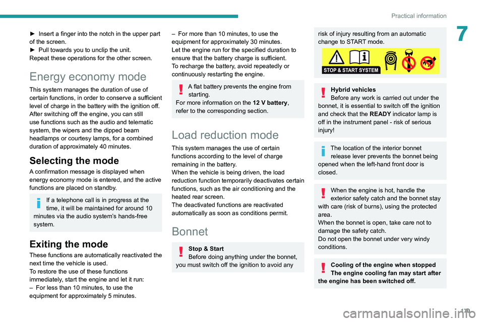
Before doing anything under the bonnet,
you must switch off the ignition to avoid any
risk of injury resulting from an automatic
change to START mode.
Hybrid vehicles
Before any work is carried out under the
bonnet, it is essential to switch off the ignition
and check that the READY indicator lamp is
off in the instrument panel - risk of serious
injury!
The location of the interior bonnet release lever prevents the bonnet being
opened when the left-hand front door is
closed.
When the engine is hot, handle the
exterior safety catch and the bonnet stay
with care (risk of burns), using the protected
area.
When the bonnet is open, take care not to
damage the safety catch.
Do not open the bonnet under very windy
conditions.
Cooling of the engine when stopped
The engine cooling fan may start after
the engine has been switched off.
Page 182 of 308
180
Practical information
8.Engine oil filler cap
9. Engine oil dipstick
10. Priming pump*
11 . Degassing screw*
The Diesel fuel system operates under
very high pressure.
All work on this circuit must be carried out
only by a PEUGEOT dealer or a qualified
workshop.
Checking levels
Check all of the following levels regularly in
accordance with the manufacturer's service
schedule. Top them up if required, unless
otherwise indicated.
If a level drops significantly, have the
corresponding system checked by a PEUGEOT
dealer or a qualified workshop.
The fluids must comply with the manufacturer's requirements and with
the vehicle's engine.
Take care when working under the bonnet, as certain areas of the engine
may be extremely hot (risk of burns) and the
cooling fan could start at any time (even with
the ignition off).
* Depending on engine.
Take care with objects or clothing that
could be caught in the blades of the fan!
Opening
► Open the left-hand front door .
► Pull the interior release lever , located at the
bottom of the door frame, towards you.
► Lift the exterior safety catch and raise the
bonnet.
► Unclip the stay from its housing and place it
in the support slot to hold the bonnet open.
Closing
► Hold the bonnet and pull out the stay from the
support slot.
►
Clip the stay in its housing.
►
Lower the bonnet and release it near the end
of its travel.
►
Pull on the bonnet to check that it is locked
correctly
.
Because of the presence of electrical
equipment under the bonnet, it is strongly
recommended that exposure to water (rain,
washing, etc.) be limited.
Engine compartment
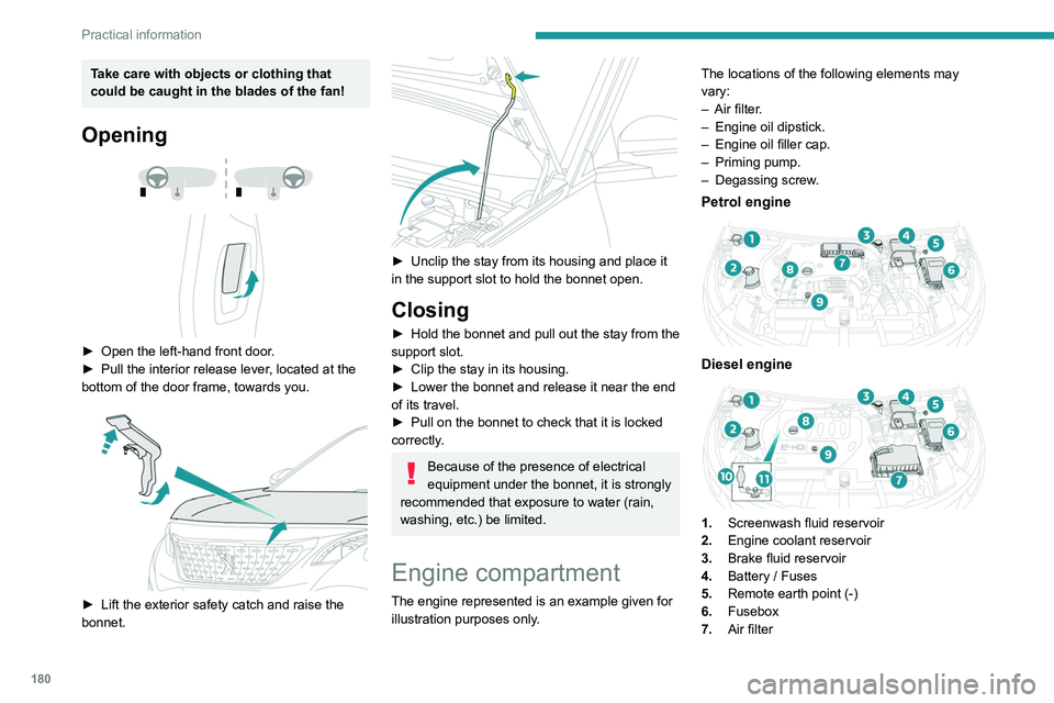
The engine represented is an example given for
illustration purposes only. The locations of the following elements may
vary:
–
Air filter
.
–
Engine oil dipstick.
–
Engine oil filler cap.
–
Priming pump.
–
Degassing screw
.
Petrol engine
Diesel engine
1.
Screenwash fluid reservoir
2. Engine coolant reservoir
3. Brake fluid reservoir
4. Battery / Fuses
5. Remote earth point (-)
6. Fusebox
7. Air filter
Page 183 of 308
181
Practical information
78.Engine oil filler cap
9. Engine oil dipstick
10. Priming pump*
11 . Degassing screw*
The Diesel fuel system operates under
very high pressure.
All work on this circuit must be carried out
only by a PEUGEOT dealer or a qualified
workshop.
Checking levels
Check all of the following levels regularly in
accordance with the manufacturer's service
schedule. Top them up if required, unless
otherwise indicated.
If a level drops significantly, have the
corresponding system checked by a PEUGEOT
dealer or a qualified workshop.
The fluids must comply with the manufacturer's requirements and with
the vehicle's engine.
Take care when working under the bonnet, as certain areas of the engine
may be extremely hot (risk of burns) and the
cooling fan could start at any time (even with
the ignition off).
* Depending on engine.
Used products
Avoid prolonged contact of used oil or fluids with the skin.
Most of these fluids are harmful to health and
very corrosive.
Do not discard used oil or fluids into
sewers or onto the ground.
Empty used oil into the containers reserved
for this purpose at a PEUGEOT dealer or a
qualified workshop.
Engine oil
The level is checked, with the engine having been switched off for at least 30
minutes and on level ground, either using the oil
level indicator in the instrument panel when the
ignition is switched on (for vehicles equipped
with an electric gauge), or using the dipstick.
It is normal to top up the oil level between two
services (or oil changes). It is recommended
that you check the level, and top up if necessary,
every 3,000 miles (5,000 km).
In order to maintain the reliability of the
engine and emissions control system,
never use additives in the engine oil.
Checking using the dipstick
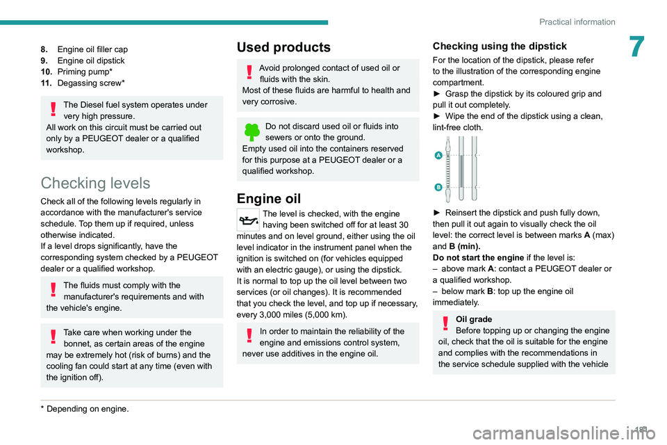
For the location of the dipstick, please refer
to the illustration of the corresponding engine
compartment.
►
Grasp the dipstick by its coloured grip and
pull it out completely
.
►
Wipe the end of the dipstick using a clean,
lint-free cloth.
► Reinsert the dipstick and push fully down,
then pull it out again to visually check the oil
level: the correct level is between marks A
(max)
and B (min).
Do not start the engine if the level is:
–
above mark
A: contact a PEUGEOT dealer or
a qualified workshop.
–
below mark B
: top up the engine oil
immediately.
Oil grade
Before topping up or changing the engine
oil, check that the oil is suitable for the engine
and complies with the recommendations in
the service schedule supplied with the vehicle
Page 184 of 308
182
Practical information
For more information on the Indicators and in
particular the AdBlue range indicators, refer to
the corresponding section.
To avoid the vehicle being immobilised in
accordance with regulations, you must top up the
AdBlue tank.
For more information on AdBlue
® (BlueHDi),
and in particular the supply of AdBlue, refer to
the corresponding section.
Checks
Unless otherwise indicated, check these
components in accordance with the
manufacturer's service schedule and according
to your engine.
Otherwise, have them checked by a PEUGEOT
dealer or a qualified workshop.
Only use products recommended by
PEUGEOT or products of equivalent
quality and specification.
In order to optimise the operation of
components as important as those in the
braking system, PEUGEOT selects and offers
very specific products.
12 V battery
The battery does not require any maintenance.
However, check regularly that the terminals
are correctly tightened (versions without quick
(or available from your PEUGEOT dealer and
qualified workshops).
Use of non-recommended oil may invalidate
the contractual warranty in the event of
engine failure.
Topping up the engine oil level
For the location of the engine oil filler cap, please
refer to the corresponding under-bonnet engine
compartment illustration.
►
Add oil in small quantities, avoiding any spills
on engine components (risk of fire).
►
W
ait a few minutes before checking the level
again using the dipstick.
►
T
op up the level if necessary.
►
After checking the level, carefully screw the
oil filler cap back on
and replace the dipstick in
its tube.
Within 30 minutes of adding oil, the oil
level indication in the instrument panel
when the ignition is switched on is not valid.
Brake fluid
The level of this fluid should be close to the "MAX" mark. If not, check the brake
pad wear.
To know how often the brake fluid should be
replaced, refer to the manufacturer's servicing
schedule.
Clean the cap before removing it to refill.
Use only DOT4 brake fluid from a sealed
container.
Engine coolant
It is normal to top up this fluid between
two services.
The check and top-up must only be done with
the engine cold.
A low level presents a risk of serious damage to
the engine.
The level of this fluid should be close to the
"MAX" mark but should never exceed it.
If the level is close to or below the " MIN” mark, it
is essential to top up.
When the engine is hot, the temperature of this
fluid is regulated by the fan.
As the cooling system is pressurised, wait at
least one hour after switching off the engine
before carrying out any work.
In order to avoid the risk of scalding if you need
to top up in an emergency, wrap a cloth around
the cap and unscrew the cap by two turns to
allow the pressure to drop.
Once the pressure has dropped, remove the cap
and top up to the required level.
Screenwash fluid
Top up to the required level when necessary.
Capacity of the tank:
–
5.3 litres for "very cold climate" versions.
– 2.2 litres for other versions.
Fluid specification
The fluid must be topped up with a ready-to-use
mixture.
In winter (temperatures below zero), a liquid
containing an agent to prevent freezing must
be used which is appropriate for the prevailing
conditions, in order to protect the elements of the
system (pump, tank, ducts, jets, etc.).
Filling with pure water is prohibited under
all circumstances (risk of freezing,
limestone deposits, etc.).
Diesel fuel additive (Diesel
with particle filter)
On reaching the minimum level in the
particle filter additive tank, this warning
lamp comes on fixed, accompanied by an
audible warning and a message warning that the
additive level is too low.
Topping up
This additive must be topped up without delay by
a PEUGEOT dealer or a qualified workshop.
AdBlue® (BlueHDi)
An alert is triggered when the reserve level is
reached.
Page 192 of 308
190
In the event of a breakdown
Warning triangle
As a safety precaution, before leaving your
vehicle to set up and install the triangle, switch
on the hazard warning lamps and put on your
high visibility vest.
Storage compartment
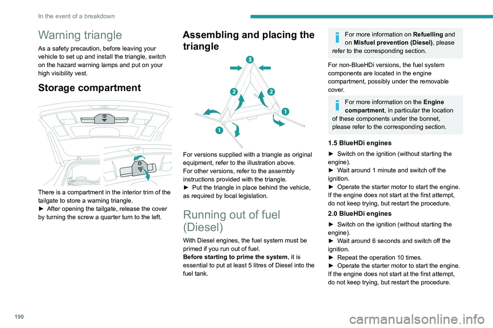
There is a compartment in the interior trim of the
tailgate to store a warning triangle.
►
After opening the tailgate, release the cover
by turning the screw a quarter turn to the left.
Assembling and placing the triangle
For versions supplied with a triangle as original
equipment, refer to the illustration above.
For other versions, refer to the assembly
instructions provided with the triangle.
►
Put the triangle in place behind the vehicle,
as required by local legislation.
Running out of fuel
(Diesel)
With Diesel engines, the fuel system must be
primed if you run out of fuel.
Before starting to prime the system, it is
essential to put at least 5 litres of Diesel into the
fuel tank.
For more information on Refuelling and
on Misfuel prevention (Diesel), please
refer to the corresponding section.
For non-BlueHDi versions, the fuel system
components are located in the engine
compartment, possibly under the removable
cover.
For more information on the Engine
compartment, in particular the location
of these components under the bonnet,
please refer to the corresponding section.
1.5 BlueHDi engines
► Switch on the ignition (without starting the
engine).
►
W
ait around 1 minute and switch off the
ignition.
►
Operate the starter motor to start the engine.
If the engine does not start at the first attempt,
do not keep trying, but restart the procedure.
2.0 BlueHDi engines
► Switch on the ignition (without starting the
engine).
►
W
ait around 6 seconds and switch off the
ignition.
►
Repeat the operation 10
times.
►
Operate the starter motor to start the engine.
If the engine does not start at the first attempt,
do not keep trying, but restart the procedure.
2.0 HDi engines
► Open the bonnet and then, if necessary,
unclip the cover to access the priming pump.
► Loosen the degassing bolt.
► Operate the priming pump until fuel
appears in the transparent tube.
► Retighten the degassing bolt.
► Operate the starter motor until the engine
starts (if the engine does not start at the first
attempt, wait around 15 seconds before trying
again).
► If the engine does not start after a few
attempts, operate the priming pump again, then
the starter motor.
► Put the cover back in place and clip it in, then
close the bonnet.
Tool kit
Set of tools supplied with the vehicle.
Its content depends on your vehicle's equipment:
– Temporary puncture repair kit.
– Spare wheel.
Accessing the tools
Page 193 of 308
191
In the event of a breakdown
82.0 HDi engines
► Open the bonnet and then, if necessary,
unclip the cover to access the priming pump.
►
Loosen the degassing bolt.
► Operate the priming pump until fuel
appears in the transparent tube.
►
Retighten the degassing bolt.
►
Operate the starter motor until the engine
starts (if the engine does not start at the first
attempt, wait around 15
seconds before trying
again).
►
If the engine does not start after a few
attempts, operate the priming pump again, then
the starter motor
.
►
Put the cover back in place and clip it in, then
close the bonnet.
Tool kit
Set of tools supplied with the vehicle.
Its content depends on your vehicle's equipment:
–
T
emporary puncture repair kit.
–
Spare wheel.
Accessing the tools
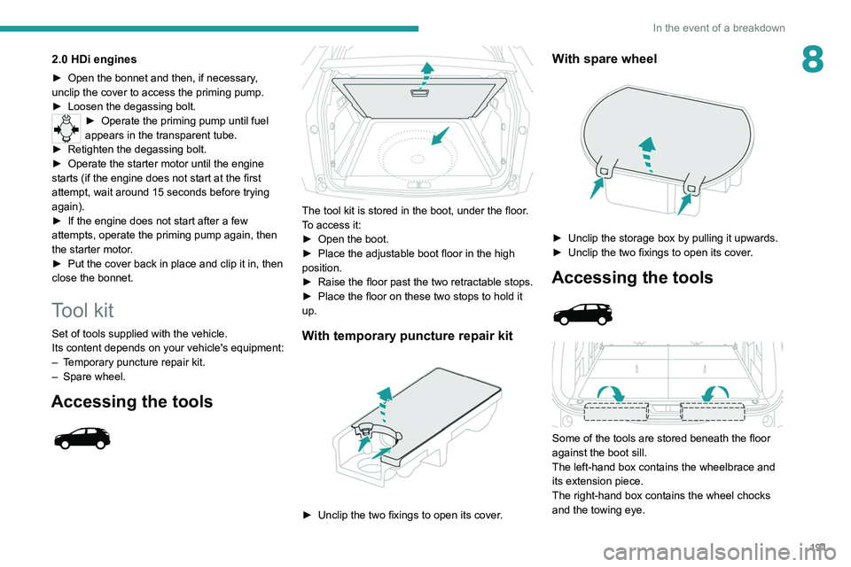
The tool kit is stored in the boot, under the floor.
To access it:
►
Open the boot.
►
Place the adjustable boot floor in the high
position.
►
Raise the floor past the two retractable stops.
►
Place the floor on these two stops to hold it
up.
With temporary puncture repair kit
► Unclip the two fixings to open its cover .
With spare wheel
► Unclip the storage box by pulling it upwards.
► Unclip the two fixings to open its cover .
Accessing the tools
Some of the tools are stored beneath the floor
against the boot sill.
The left-hand box contains the wheelbrace and
its extension piece.
The right-hand box contains the wheel chocks
and the towing eye.
Page 204 of 308
202
In the event of a breakdown
Always replace a failed bulb with a new bulb
of the same type and specification. To avoid
lighting imbalance, replace the bulbs in pairs.
Refitting the lamp units
Perform the operations in the reverse
order to dismantling.
Light-emitting diode (LED)
headlamps and lamps
Depending on version, the affected types of
headlamps / lamps are:
–
Full LED technology headlamps.
–
Direction indicator side repeaters.
–
Side spotlamps.
–
Third brake lamp.
For the replacement of this type of bulb,
you must contact a PEUGEOT dealer or
a qualified workshop.
Do not touch the "Full LED" technology
headlamps - risk of electrocution!
Front lamps
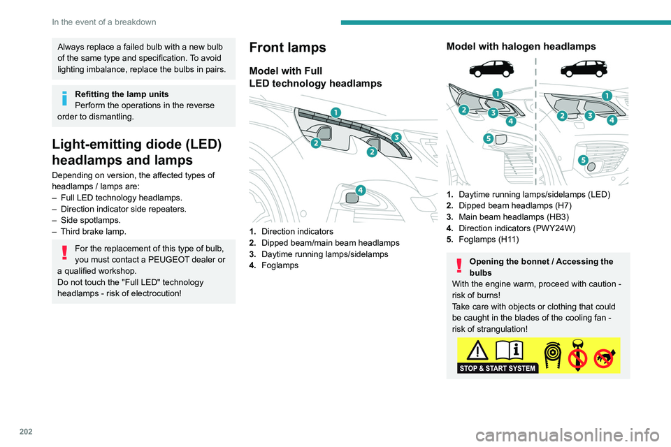
Model with Full
LED technology headlamps
1.Direction indicators
2. Dipped beam/main beam headlamps
3. Daytime running lamps/sidelamps
4. Foglamps
Model with halogen headlamps
1.Daytime running lamps/sidelamps (LED)
2. Dipped beam headlamps (H7)
3. Main beam headlamps (HB3)
4. Direction indicators (PWY24W)
5. Foglamps (H11)
Opening the bonnet / Accessing the
bulbs
With the engine warm, proceed with caution -
risk of burns!
Take care with objects or clothing that could
be caught in the blades of the cooling fan -
risk of strangulation!
Halogen bulbs (Hx)
To ensure good quality lighting, check
that the bulb is correctly positioned in its
housing.
Direction indicators
Rapid flashing of a direction indicator
lamp (left or right) indicates that one of
the bulbs on the corresponding side has
failed.
► Turn the connector a quarter turn
anti-clockwise.
► Pull the bulb connector.
► Remove the bulb and replace it.
Amber coloured bulbs must be replaced
by bulbs with identical specifications and
colour.