2020 NISSAN ROGUE SPORT fuel
[x] Cancel search: fuelPage 194 of 492
3-28Pre-driving checks and adjustments
WARNING
.Fuel is extremely flammable and
highly explosive under certain
conditions. You could be burned
or seriously injured if it is misused
or mishandled. Always stop the
engine and do not smoke or allow
open flames or sparks near the
vehicle when refueling.
. Fuel may be under pressure. Turn
the cap a half of a turn, and wait
for any “hissing” sound to stop to
prevent fuel from spraying out
and possibly causing personal
injury. Then remove the cap.
. Use only an original equipment
type fuel-filler cap as a replace-
ment. It has a built-in safety valve
needed for proper operation of
the fuel system and emission
control system. An incorrect cap
can result in a serious malfunc-
tion and possible injury.
JVP0540X
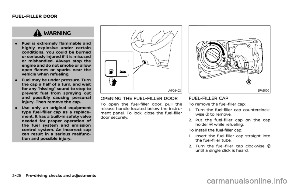
OPENING THE FUEL-FILLER DOOR
To open the fuel-filler door, pull the
release handle located below the instru-
ment panel. To lock, close the fuel-filler
door securely.
SPA2800
FUEL-FILLER CAP
To remove the fuel-filler cap:
1. Turn the fuel-filler cap counterclock-
wise
to remove.
2. Put the fuel-filler cap on the cap holder
while refueling.
To install the fuel-filler cap:
1. Insert the fuel-filler cap straight into the fuel-filler tube.
2. Turn the fuel-filler cap clockwise
until a single click is heard.
FUEL-FILLER DOOR
Page 195 of 492
WARNING
.Gasoline is extremely flammable
and highly explosive under cer-
tain conditions. You could be
burned or seriously injured if it is
misused or mishandled. Always
stop engine and do not smoke or
allow open flames or sparks near
the vehicle when refueling.
. Do not attempt to top off the fuel
tank after the fuel pump nozzle
shuts off automatically. Contin-
ued refueling may cause fuel
overflow, resulting in fuel spray
and possibly a fire.
. Use only an original equipment
type fuel-filler cap as a replace-
ment. It has a built-in safety valve
needed for proper operation of
the fuel system and emission
control system. An incorrect cap
can result in a serious malfunc-
tion and possible injury. It could
also cause the malfunction indi-
cator light to come on.
. Never pour fuel into the throttle
body to attempt to start your
vehicle. .
Do not fill a portable fuel contain-
er in the vehicle or trailer. Static
electricity can cause an explosion
of flammable liquid, vapor or gas
in any vehicle or trailer. To reduce
the risk of serious injury or death
when filling portable fuel contain-
ers:
— Always place the container on
the ground when filling.
— Do not use electronic devices when filling.
— Keep the pump nozzle in con- tact with the container while
you are filling it.
— Use only approved portable fuel containers for flammable
liquid.
CAUTION
. If fuel is spilled on the vehicle
body, flush it away with water to
avoid paint damage.
. Insert the cap straight into the
fuel-filler tube, then tighten until
the fuel-filler cap clicks. Failure to
tighten the fuel-filler cap properly
may cause the
malfunction indicator light (MIL) to illuminate.
If the
light illuminates be-
cause the fuel-filler cap is loose
or missing, tighten or install the
cap and continue to drive the
vehicle. The
light should turn
off after a few driving trips. If the
light does not turn off after a
few driving trips, have the vehicle
inspected. It is recommended you
visit a NISSAN dealer for this
service.
For additional information, see
“Malfunction Indicator Light
(MIL)” (P.2-17).
. The LOOSE FUEL CAP warning
message will be displayed if the
fuel-filler cap is not properly tigh-
tened. It may take a few driving
trips for the message to be dis-
played. Failure to tighten the fuel-
filler cap properly after the LOOSE
FUEL CAP warning message is
displayed may cause the
Malfunction Indicator Light (MIL)
to illuminate.
Pre-driving checks and adjustments3-29
Page 196 of 492

3-30Pre-driving checks and adjustments
JVP0503X
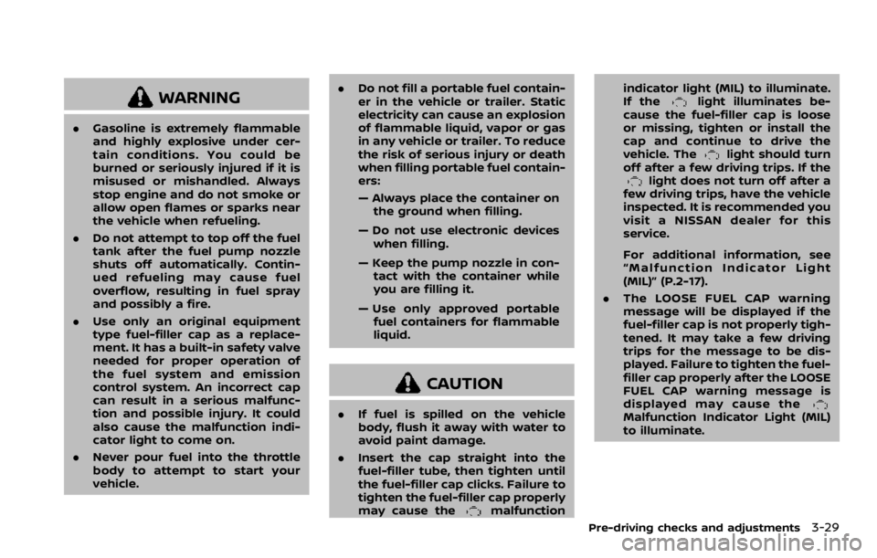
LOOSE FUEL CAP warning message
The LOOSE FUEL CAP warning messageis displayed on the vehicle information
display when the fuel-filler cap is not
tightened correctly after the vehicle has
been refueled. It may take a few driving
trips for the message to be displayed. To
turn off the warning message, do the
following procedure:
1. Remove and install the fuel-filler capas soon as possible. For additional
information, refer to “Fuel-filler cap”
(P.3-28).
2. Tighten the fuel-filler cap until it clicks. 3. Push the OK button
on the steering
wheel for about 1 second to turn off
the LOOSE FUEL CAP warning mes-
sage after tightening the fuel cap.
WARNING
Do not adjust the steering wheel
while driving. You could lose control
of your vehicle and cause an acci-
dent.
TILT/TELESCOPIC STEERING
Page 210 of 492
4-8Monitor, heater, air conditioner, audio and phone systems
.Underneath the bumper and the
corner areas of the bumper can-
not be viewed on the RearView
Monitor because of its monitoring
range limitation. The system will
not show small objects below the
bumper, and may not show ob-
jects close to the bumper or on
the ground.
. Objects viewed in the RearView
Monitor differ from actual dis-
tance because a wide-angle lens
is used.
. Objects in the RearView Monitor
will appear visually opposite
compared to when viewed in the
rearview and outside mirrors.
. Use the displayed lines as a re-
ference. The lines are highly af-
fected by the number of
occupants, fuel level, vehicle po-
sition, road conditions and road
grade.
. Make sure that the liftgate is
securely closed when backing up.
. Do not put anything on the rear-
view camera. The rearview cam-
era is installed above the license
plate. .
When washing the vehicle with
high-pressure water, be sure not
to spray it around the camera.
Otherwise, water may enter the
camera unit causing water con-
densation on the lens, a malfunc-
tion, fire or an electric shock.
. Do not strike the camera. It is a
precision instrument. Otherwise,
it may malfunction or cause da-
mage resulting in a fire or an
electric shock.
The following are operating limitations
and do not represent a system malfunc-
tion:
. When the temperature is extremely
high or low, the screen may not clearly
display objects.
. When strong light directly shines on
the camera, objects may not be dis-
played clearly.
. Vertical lines may be seen in objects
on the screen. This is due to strong
reflected light from the bumper.
. The screen may flicker under fluores-
cent light.
. The colors of objects on the RearView
Monitor may differ somewhat from
the actual color of objects. .
Objects on the monitor may not be
clear in a dark environment.
. There may be a delay when switching
between views.
. If dirt, rain or snow accumulates on
the camera, the RearView Monitor
may not display objects clearly. Clean
the camera.
. Do not use wax on the camera lens.
Wipe off any wax with a clean cloth
dampened with a diluted mild clean-
ing agent, then wipe with a dry cloth.
Page 213 of 492
Available views:
.Front view
The view to the front of the vehicle.
. Rear view
The view to the rear of the vehicle.
. Bird’s-eye view
The views to the vehicle from above.
. Front-side view
The view around and ahead of the
front passenger’s side wheel.
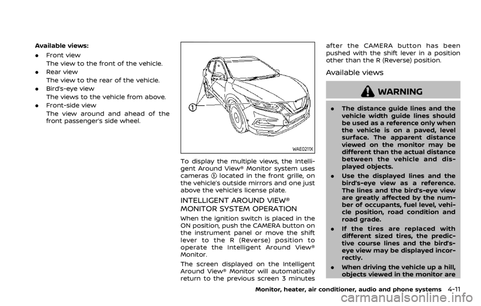
WAE0211X
To display the multiple views, the Intelli-
gent Around View® Monitor system uses
cameras
located in the front grille, on
the vehicle’s outside mirrors and one just
above the vehicle’s license plate.
INTELLIGENT AROUND VIEW®
MONITOR SYSTEM OPERATION
When the ignition switch is placed in the
ON position, push the CAMERA button on
the instrument panel or move the shift
lever to the R (Reverse) position to
operate the Intelligent Around View®
Monitor.
The screen displayed on the Intelligent
Around View® Monitor will automatically
return to the previous screen 3 minutes after the CAMERA button has been
pushed with the shift lever in a position
other than the R (Reverse) position.
Available views
WARNING
.
The distance guide lines and the
vehicle width guide lines should
be used as a reference only when
the vehicle is on a paved, level
surface. The apparent distance
viewed on the monitor may be
different than the actual distance
between the vehicle and dis-
played objects.
. Use the displayed lines and the
bird’s-eye view as a reference.
The lines and the bird’s-eye view
are greatly affected by the num-
ber of occupants, fuel level, vehi-
cle position, road condition and
road grade.
. If the tires are replaced with
different sized tires, the predic-
tive course lines and the bird’s-
eye view may be displayed incor-
rectly.
. When driving the vehicle up a hill,
objects viewed in the monitor are
Monitor, heater, air conditioner, audio and phone systems4-11
Page 239 of 492

Turning the I-FCW system ON/OFF ................. 5-108
I-FCW system limitations .......................................... 5-110
System temporarily unavailable ......................... 5-112
System malfunction ...................................................... 5-112
System maintenance ................................................... 5-113
Rear Automatic Braking (RAB) .................................... 5-114 RAB system operation ................................................ 5-115
Turning the RAB system ON/OFF ...................... 5-115
RAB system limitations .............................................. 5-116
System malfunction ...................................................... 5-118
System maintenance ................................................... 5-119
Break-in schedule ................................................................. 5-119
Fuel Efficient Driving Tips ................................................ 5-120
Increasing fuel economy ................................................. 5-121
Intelligent 4x4 (if so equipped) ................................... 5-121 Intelligent 4x4 LOCK switch operations ...... 5-123
Parking/parking on hills ................................................... 5-125
Electric power steering ..................................................... 5-126
Brake system ........................................................................\
.... 5-127 Braking precautions ..................................................... 5-127
Brake assist ........................................................................\
........ 5-128
Brake assist ........................................................................\
. 5-128
Anti-lock Braking System (ABS) ........................... 5-128 Vehicle Dynamic Control (VDC) system .............. 5-129
Chassis control ....................................................................... 5-131
Intelligent Trace Control ......................................... 5-131
Intelligent Engine Brake (Continuously
Variable Transmission (CVT) models) .......... 5-132
Active Ride Control ..................................................... 5-133
Hill Start Assist system ..................................................... 5-134
Rear Sonar System (RSS) ................................................ 5-134
System operation ......................................................... 5-135
How to enable/disable the RSS ........................ 5-137
RSS limitations ................................................................ 5-138
System temporarily unavailable ....................... 5-138
System maintenance ................................................ 5-138
Cold weather driving ......................................................... 5-139
Freeing a frozen door lock ................................... 5-139
Anti-freeze ........................................................................\
.. 5-139
Battery ........................................................................\
........... 5-139
Draining of coolant water ..................................... 5-139
Tire equipment ............................................................... 5-139
Special winter equipment ..................................... 5-140
Driving on snow or ice ............................................. 5-140
Page 241 of 492
away from the exhaust system
components.
. Do not stop or park the vehicle
over flammable materials such as
dry grass, wastepaper or rags.
They may ignite and cause a fire.
CAUTION
.Do not use leaded gasoline. De-
posits from leaded gasoline will
seriously reduce the three-way
catalyst’s ability to help reduce
exhaust pollutants.
. Keep your engine tuned up. Mal-
functions in the ignition, fuel in-
jection, or electrical systems can
cause overrich fuel flow into the
three-way catalyst, causing it to
overheat. Do not keep driving if
the engine misfires, or if notice-
able loss of performance or other
unusual operating conditions are
detected. Have the vehicle in-
spected. It is recommended you
visit a NISSAN dealer for this
service.
. Avoid driving with an extremely
low fuel level. Running out of fuel
could cause the engine to misfire, damaging the three-way catalyst.
. Do not race the engine while
warming it up.
. Do not push or tow your vehicle
to start the engine.
TIRE PRESSURE MONITORING SYS-
TEM (TPMS)
Each tire, including the spare (if provided),
should be checked monthly when cold
and inflated to the inflation pressure
recommended by the vehicle manufac-
turer on the vehicle placard or tire infla-
tion pressure label. (If your vehicle has
tires of a different size than the size
indicated on the vehicle placard or tire
inflation pressure label, you should deter-
mine the proper tire inflation pressure for
those tires.)
As an added safety feature, your vehicle
has been equipped with a Tire Pressure
Monitoring System (TPMS) that illumi-
nates a low tire pressure telltale when
one or more of your tires is significantly
under-inflated. Accordingly, when the low
tire pressure telltale illuminates, you
should stop and check your tires as soon
as possible, and inflate them to the
proper pressure. Driving on a significantly
under-inflated tire causes the tire to
overheat and can lead to tire failure. Under-inflation also reduces fuel effi-
ciency and tire tread life, and may affect
the vehicle’s handling and stopping abil-
ity.
Please note that the TPMS is not a
substitute for proper tire maintenance,
and it is the driver’s responsibility to
maintain correct tire pressure, even if
under-inflation has not reached the level
to trigger illumination of the TPMS low
tire pressure telltale.
Your vehicle has also been equipped with
a TPMS malfunction indicator to indicate
when the system is not operating prop-
erly. The TPMS malfunction indicator is
combined with the low tire pressure tell-
tale. When the system detects a malfunc-
tion, the telltale will flash for
approximately one minute and then re-
main continuously illuminated. This se-
quence will continue upon subsequent
vehicle start-ups as long as the malfunc-
tion exists. When the malfunction indica-
tor is illuminated, the system may not be
able to detect or signal low tire pressure
as intended. TPMS malfunctions may
occur for a variety of reasons, including
the installation of replacement or alter-
nate tires or wheels on the vehicle that
prevent the TPMS from functioning prop-
erly. Always check the TPMS malfunction
telltale after replacing one or more tires
Starting and driving5-5
Page 253 of 492

JVS0404X
INTELLIGENT KEY BATTERY DIS-
CHARGE
If the battery of the Intelligent Key is
discharged, or environmental conditions
interfere with the Intelligent Key opera-
tion, start the engine according to the
following procedure:
1. Move the shift lever to the P (Park)position (for CVT models) or the shift
lever to the N (Neutral) position (for MT
models).
2. Firmly apply the foot brake.
3. Touch the ignition switch with the Intelligent Key as illustrated. (A chime
will sound.) 4. Push the ignition switch while depres-
sing the brake pedal within 10 sec-
onds after the chime sounds. The
engine will start.
After step 3 is performed, when the
ignition switch is pushed without depres-
sing the brake pedal, the ignition switch
position will change to ACC.
NOTE:
. When the ignition switch is pushed
to the ON position or the engine is
started by the above procedures, the
“Key Battery Low” warning appears
(on the Vehicle information display)
even if the Intelligent Key is inside
the vehicle. This is not a malfunction.
To turn off the warning, touch the
ignition switch with the Intelligent
Key again.
. If the “Key Battery Low” warning
appears (on the Vehicle information
display), replace the battery as soon
as possible. (See “Intelligent Key
battery replacement” (P.8-23).)
.Make sure the area around the vehicle
is clear.
. Check fluid levels such as engine oil,
coolant, brake fluid, and window
washer fluid as frequently as possible,
or at least whenever you refuel.
. Check that all windows and lights are
clean.
. Visually inspect tires for their appear-
ance and condition. Also check tires
for proper inflation.
. Lock all doors.
. Position seat and adjust head re-
straints.
. Adjust inside and outside mirrors.
. Fasten seat belts and ask all passen-
gers to do likewise.
. Check the operation of warning lights
when the ignition switch is placed in
the ON position. (See “Warning lights,
indicator lights and audible remin-
ders” (P.2-10).)
Starting and driving5-17
BEFORE STARTING THE ENGINE