2020 NISSAN ROGUE SPORT tow
[x] Cancel search: towPage 177 of 492
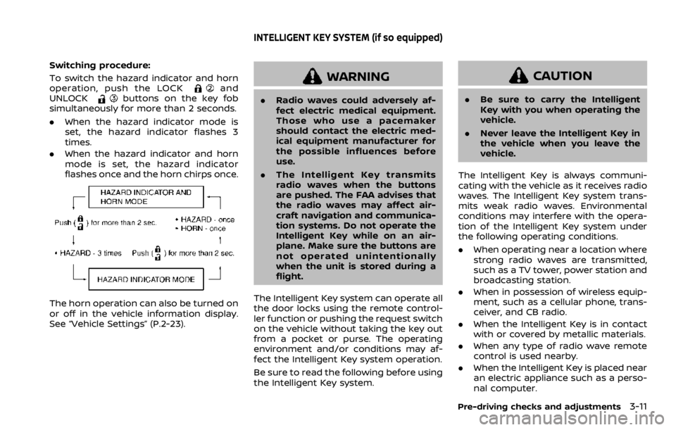
Switching procedure:
To switch the hazard indicator and horn
operation, push the LOCK
and
UNLOCKbuttons on the key fob
simultaneously for more than 2 seconds.
. When the hazard indicator mode is
set, the hazard indicator flashes 3
times.
. When the hazard indicator and horn
mode is set, the hazard indicator
flashes once and the horn chirps once.
The horn operation can also be turned on
or off in the vehicle information display.
See “Vehicle Settings” (P.2-23).
WARNING
.Radio waves could adversely af-
fect electric medical equipment.
Those who use a pacemaker
should contact the electric med-
ical equipment manufacturer for
the possible influences before
use.
. The Intelligent Key transmits
radio waves when the buttons
are pushed. The FAA advises that
the radio waves may affect air-
craft navigation and communica-
tion systems. Do not operate the
Intelligent Key while on an air-
plane. Make sure the buttons are
not operated unintentionally
when the unit is stored during a
flight.
The Intelligent Key system can operate all
the door locks using the remote control-
ler function or pushing the request switch
on the vehicle without taking the key out
from a pocket or purse. The operating
environment and/or conditions may af-
fect the Intelligent Key system operation.
Be sure to read the following before using
the Intelligent Key system.
CAUTION
. Be sure to carry the Intelligent
Key with you when operating the
vehicle.
. Never leave the Intelligent Key in
the vehicle when you leave the
vehicle.
The Intelligent Key is always communi-
cating with the vehicle as it receives radio
waves. The Intelligent Key system trans-
mits weak radio waves. Environmental
conditions may interfere with the opera-
tion of the Intelligent Key system under
the following operating conditions.
. When operating near a location where
strong radio waves are transmitted,
such as a TV tower, power station and
broadcasting station.
. When in possession of wireless equip-
ment, such as a cellular phone, trans-
ceiver, and CB radio.
. When the Intelligent Key is in contact
with or covered by metallic materials.
. When any type of radio wave remote
control is used nearby.
. When the Intelligent Key is placed near
an electric appliance such as a perso-
nal computer.
Pre-driving checks and adjustments3-11
INTELLIGENT KEY SYSTEM (if so equipped)
Page 190 of 492

3-24Pre-driving checks and adjustments
3. Within 5 seconds push and hold theremote engine startbutton until
the turn signal lights flash and the tail
lights illuminate. If the vehicle is not
within view, push and hold the remote
engine start
button for at least 2
seconds.
The following events will occur when the
engine starts:
. The front parking lights will turn on
and remain on as long as the engine is
running.
. The doors will be locked and the air
conditioner system may turn on.
. The engine will continue to run for
about 10 minutes. Repeat the steps to
extend the time for an additional 10
minutes. See “Extending engine run
time” (P.3-24).
Depress and hold the brake pedal, then
place the ignition switch in the ON posi-
tion before driving. For further instruc-
tions, see “Driving the vehicle” (P.5-20).
EXTENDING ENGINE RUN TIME
The remote engine start function can be
extended one time by performing the
steps listed in “Remote starting the en-
gine” (P.3-23). Run time will be calculated
as follows:
. The first 10 minute run time will start
when the remote engine start func- tion is performed.
. The second 10 minutes will start im-
mediately when the remote engine
start function is performed. For exam-
ple, if the engine has been running for
5 minutes, and 10 minutes are added,
the engine will run for a total of 15
minutes.
. Extending engine run time will count
towards the two remote engine start
limit.
A maximum of two remote engine starts,
or a single start with an extension, are
allowed between ignition cycles.
The ignition switch must be cycled to the
ON position and then back to the OFF
position before the remote engine start
procedure can be used again.
CANCELING A REMOTE ENGINE
START
To cancel a remote engine start, perform
one of the following:
. Aim the Intelligent Key at the vehicle
and push and hold the remote engine
start
button until the front park-
ing lights turn off.
. Turn on the hazard indicator flashers.
. Cycle the ignition switch ON and then
OFF. .
The extended engine run time has
expired.
. The first 10 minute timer has expired.
. The engine hood has been opened.
. The shift lever is moved out of the P
(Park) position.
. The theft alarm sounds due to illegal
entry into the vehicle.
. The ignition switch is pushed without
an Intelligent Key in the vehicle.
. The ignition switch is pushed with an
Intelligent Key in the vehicle but the
brake pedal is not depressed.
CONDITIONS THE REMOTE ENGINE
START WILL NOT WORK
The remote engine start will not operate
if any of the following conditions are
present:
.The ignition switch is placed in the ON
position.
. The hood is not securely closed.
. The hazard indicator flashers are on.
. The engine is still running. The engine
must be completely stopped. Wait at
least 6 seconds if the engine goes
from running to off. This is not applic-
able when extending engine run time.
. The remote engine start
button is
not pushed and held for at least 2
seconds.
Page 200 of 492

3-34Pre-driving checks and adjustments
SPA1829
Foldable outside mirrors
Fold the outside mirror by pushing it
toward the rear of the vehicle.
SIC3869
VANITY MIRROR
To use the front vanity mirror, pull down
the sun visor and pull up the cover.The automatic drive positioner system
has two features:
.
Memory storage function
. Entry/exit function
AUTOMATIC DRIVE POSITIONER (if
so equipped)
Page 241 of 492
away from the exhaust system
components.
. Do not stop or park the vehicle
over flammable materials such as
dry grass, wastepaper or rags.
They may ignite and cause a fire.
CAUTION
.Do not use leaded gasoline. De-
posits from leaded gasoline will
seriously reduce the three-way
catalyst’s ability to help reduce
exhaust pollutants.
. Keep your engine tuned up. Mal-
functions in the ignition, fuel in-
jection, or electrical systems can
cause overrich fuel flow into the
three-way catalyst, causing it to
overheat. Do not keep driving if
the engine misfires, or if notice-
able loss of performance or other
unusual operating conditions are
detected. Have the vehicle in-
spected. It is recommended you
visit a NISSAN dealer for this
service.
. Avoid driving with an extremely
low fuel level. Running out of fuel
could cause the engine to misfire, damaging the three-way catalyst.
. Do not race the engine while
warming it up.
. Do not push or tow your vehicle
to start the engine.
TIRE PRESSURE MONITORING SYS-
TEM (TPMS)
Each tire, including the spare (if provided),
should be checked monthly when cold
and inflated to the inflation pressure
recommended by the vehicle manufac-
turer on the vehicle placard or tire infla-
tion pressure label. (If your vehicle has
tires of a different size than the size
indicated on the vehicle placard or tire
inflation pressure label, you should deter-
mine the proper tire inflation pressure for
those tires.)
As an added safety feature, your vehicle
has been equipped with a Tire Pressure
Monitoring System (TPMS) that illumi-
nates a low tire pressure telltale when
one or more of your tires is significantly
under-inflated. Accordingly, when the low
tire pressure telltale illuminates, you
should stop and check your tires as soon
as possible, and inflate them to the
proper pressure. Driving on a significantly
under-inflated tire causes the tire to
overheat and can lead to tire failure. Under-inflation also reduces fuel effi-
ciency and tire tread life, and may affect
the vehicle’s handling and stopping abil-
ity.
Please note that the TPMS is not a
substitute for proper tire maintenance,
and it is the driver’s responsibility to
maintain correct tire pressure, even if
under-inflation has not reached the level
to trigger illumination of the TPMS low
tire pressure telltale.
Your vehicle has also been equipped with
a TPMS malfunction indicator to indicate
when the system is not operating prop-
erly. The TPMS malfunction indicator is
combined with the low tire pressure tell-
tale. When the system detects a malfunc-
tion, the telltale will flash for
approximately one minute and then re-
main continuously illuminated. This se-
quence will continue upon subsequent
vehicle start-ups as long as the malfunc-
tion exists. When the malfunction indica-
tor is illuminated, the system may not be
able to detect or signal low tire pressure
as intended. TPMS malfunctions may
occur for a variety of reasons, including
the installation of replacement or alter-
nate tires or wheels on the vehicle that
prevent the TPMS from functioning prop-
erly. Always check the TPMS malfunction
telltale after replacing one or more tires
Starting and driving5-5
Page 252 of 492

5-16Starting and driving
Continuously Variable Transmis-
sion (CVT) models
The ignition lock is designed so that the
ignition switch position cannot be
switched to OFF until the shift lever is
moved to the P (Park) position.
When the ignition switch cannot be
pushed toward the OFF position, proceed
as follows:
1. Move the shift lever into the P (Park)position.
2. Push the ignition switch. The ignition switch position will change to the ON
position.
3. Push the ignition switch again to the OFF position.
The shift lever can be moved from the P
(Park) position if the ignition switch is in
the ON position and the brake pedal is
depressed.
PUSH-BUTTON IGNITION SWITCH
POSITIONS
LOCK (Normal parking position)
The ignition switch can only be locked at
this position.
The ignition switch will lock when any
door is opened or closed with the ignition
switched off.
ON (Normal operating position)
The ignition system and the electrical
accessory power activate at this position
without the engine turned on.
The ON position has a battery saver
feature that will place the ignition switch
in the OFF position, if the vehicle is not
running, after some time under the fol-
lowing conditions:
. all doors are closed.
. shift lever is in P (Park) position (CVT
model) or N (Neutral) position (MT
model).
The battery saver feature will be can-
celled if any of the following occur:
. any door is opened.
. shift lever is moved out of the P (Park)
position (CVT model). .
ignition switch changes position.
OFF position
The engine is turned off in this position.
Auto ACC position
With the vehicle in the P (Park) position
(CVT models) or the N (Neutral) position
(MT models), the Intelligent Key with you
and the ignition placed from ON to OFF,
the radio can still be used for a period of
time, or until the driver’s door is opened.
After a period of time, functions such as
radio, navigation (if so equipped), and
Bluetooth® Hands-Free Phone System
may be restarted by turning on the audio
system (see the separate NissanConnect®
Owner’s Manual), or by pushing the UN-
LOCK button on the Intelligent Key for up
to a total of 30 minutes.
EMERGENCY ENGINE SHUT OFF
To shut off the engine in an emergency
situation while driving, perform the fol-
lowing procedure:
.Rapidly push the push-button ignition
switch 3 consecutive times in less
than 1.5 seconds, or
. Push and hold the push-button igni-
tion switch for more than 2 seconds.
Page 266 of 492
5-30Starting and driving
.Be sure to deactivate the auto-
matic brake hold function when
using a car wash or towing your
vehicle.
. Make sure to place the shift lever
in the P (Park) position and apply
the parking brake when parking
your vehicle, riding on or off the
vehicle, or loading luggage. Fail-
ure to do so could cause the
vehicle to move or roll away
unexpectedly and result in ser-
ious personal injury or property
damage.
. If any of the following conditions
occur, the automatic brake hold
function may not function. Have
the system checked promptly. It
is recommended that you visit a
NISSAN dealer for this service.
Failure to operate the vehicle in
accordance with these conditions
could cause the vehicle to move
or roll away unexpectedly and
result in serious personal injury
or property damage.
— A warning message appears
in the vehicle information dis-
play.
— The indicator light on the automatic brake hold switch does not illuminate when the
switch is pushed.
. The automatic brake hold func-
tion will not be activated if the
Vehicle Dynamic Control (VDC)
OFF indicator light, electronic
parking brake warning light or
master warning light illuminate
and the Chassis Control System
Error message appears in the
vehicle information display.
. To maintain the braking force to
keep the vehicle to a standstill, a
noise may be heard. This is not a
malfunction.
JVP0497X
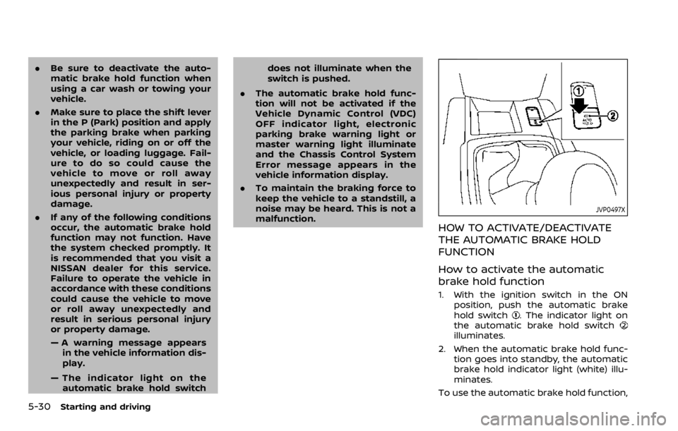
HOW TO ACTIVATE/DEACTIVATE
THE AUTOMATIC BRAKE HOLD
FUNCTION
How to activate the automatic
brake hold function
1. With the ignition switch in the ON
position, push the automatic brake
hold switch
. The indicator light on
the automatic brake hold switch
illuminates.
2. When the automatic brake hold func- tion goes into standby, the automatic
brake hold indicator light (white) illu-
minates.
To use the automatic brake hold function,
Page 346 of 492
5-110Starting and driving
JVS0298X
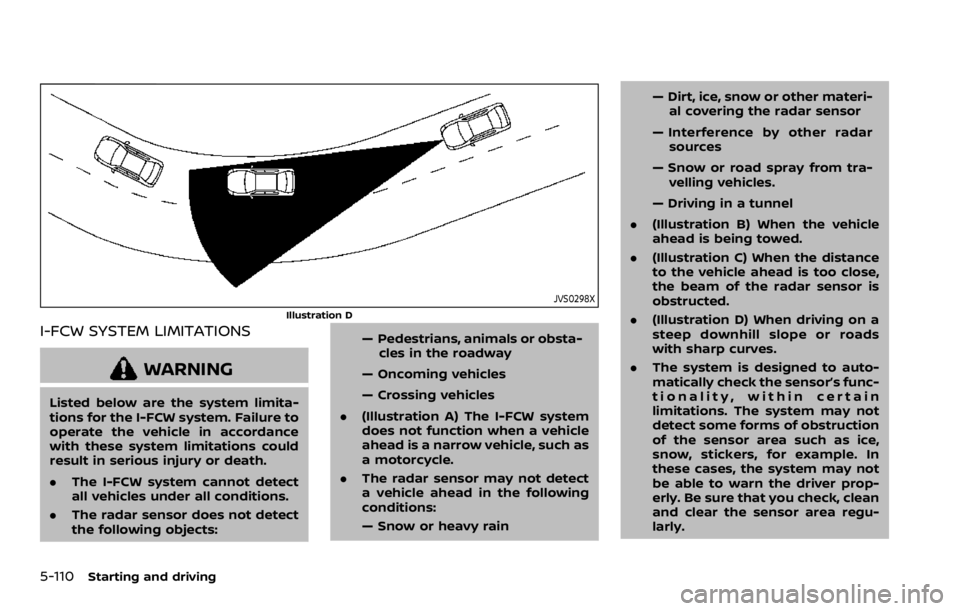
Illustration D
I-FCW SYSTEM LIMITATIONS
WARNING
Listed below are the system limita-
tions for the I-FCW system. Failure to
operate the vehicle in accordance
with these system limitations could
result in serious injury or death.
.The I-FCW system cannot detect
all vehicles under all conditions.
. The radar sensor does not detect
the following objects: — Pedestrians, animals or obsta-
cles in the roadway
— Oncoming vehicles
— Crossing vehicles
. (Illustration A) The I-FCW system
does not function when a vehicle
ahead is a narrow vehicle, such as
a motorcycle.
. The radar sensor may not detect
a vehicle ahead in the following
conditions:
— Snow or heavy rain — Dirt, ice, snow or other materi-
al covering the radar sensor
— Interference by other radar sources
— Snow or road spray from tra- velling vehicles.
— Driving in a tunnel
. (Illustration B) When the vehicle
ahead is being towed.
. (Illustration C) When the distance
to the vehicle ahead is too close,
the beam of the radar sensor is
obstructed.
. (Illustration D) When driving on a
steep downhill slope or roads
with sharp curves.
. The system is designed to auto-
matically check the sensor’s func-
tionality, within certain
limitations. The system may not
detect some forms of obstruction
of the sensor area such as ice,
snow, stickers, for example. In
these cases, the system may not
be able to warn the driver prop-
erly. Be sure that you check, clean
and clear the sensor area regu-
larly.
Page 354 of 492
5-118Starting and driving
— The vehicle is driven in badweather (rain, fog, snow, etc.).
— The vehicle is driven on a steep hill.
— The vehicle’s posture is chan- ged (e.g., when driving over a
bump).
— The vehicle is driven on a slippery road.
— The vehicle is turned sharply by turning the steering wheel
fully.
— Snow chains are used.
— Wheels or tires other than NISSAN recommended are
used.
— The brakes are cold at low ambient temperatures or im-
mediately after driving has
started.
— The braking force becomes poor due to wet brakes after
driving through a puddle or
washing the vehicle.
. Turn the RAB system off in the
following conditions to prevent
the occurrence of an unexpected
accident resulting from sudden
system operation: — The vehicle is towed.
— The vehicle is carried on a
flatbed truck.
— The vehicle is on the chassis dynamometer.
— The vehicle drives on an un- even road surface.
— Suspension parts other than those designated as genuine
parts are used. (If the vehicle
height or the vehicle body
inclination is changed, the
system may not detect an
obstacle correctly.)
. Excessive noise (e.g., audio sys-
tem volume, an open vehicle win-
dow) will interfere with the chime
sound, and it may not be heard.SYSTEM MALFUNCTION
If the RAB system malfunctions, it will be
turned off automatically, the RAB system
warning light will illuminate, and the
“Malfunction” warning message will ap-
pear in the vehicle information display.
Action to take
If the warning light illuminates, park the
vehicle in a safe location, turn the engine
off, and restart the engine. If the warning
light continues to illuminate, have the
RAB system checked. It is recommended
that you visit a NISSAN dealer for this
service.
NOTE:
If the RAB system cannot be operated
temporarily, the RAB system warning
light blinks.