Page 228 of 300
Under some driving or climate conditions,
occasional brake squeak, squeal or other
noise may be heard. Occasional brake
noise during light to moderate stops is nor-
mal and does not affect the function or
performance of the brake system.
Proper brake inspection intervals should
be followed.For additional information re-
garding brake inspections, refer to the ap-
propriate maintenance schedule informa-
tion in the “Maintenance and schedules”
section of this manual.
If any electrical equipment does not oper-
ate, check for an open fuse.
Fuses are used in the passenger and en-
gine compartment. Spare fuses are pro-
vided and can be found in the passenger
compartment fuse box.
When installing a fuse make sure the fuse is
installed in the fuse box securely.
NOTE:
Your vehicle may not be equipped with
all fuses listed on the fuse label.
ENGINE COMPARTMENT
Page 231 of 300
Extended storage switch
If any electrical equipment does not oper-
ate, remove the extended storage switch
and check for an open fuse.
NOTE:
The extended storage switch is used for
long term vehicle storage. Even if the ex-
tended storage switch is broken it is not
necessary to replace it. Replace only the
open fuse in the switch with a new fuse.How to replace the extended storage
switch:
1. To remove the extended storage switch, be sure the ignition switch is in
the OFF or LOCK position.
2. Be sure the headlight switch is in the OFF position.
3. Remove the fuse box cover.
4. Pinch the locking tabs
�1and�2found
on each side of the storage switch.
5. Pull the storage switch straight out from the fuse box
�3.
Page 234 of 300
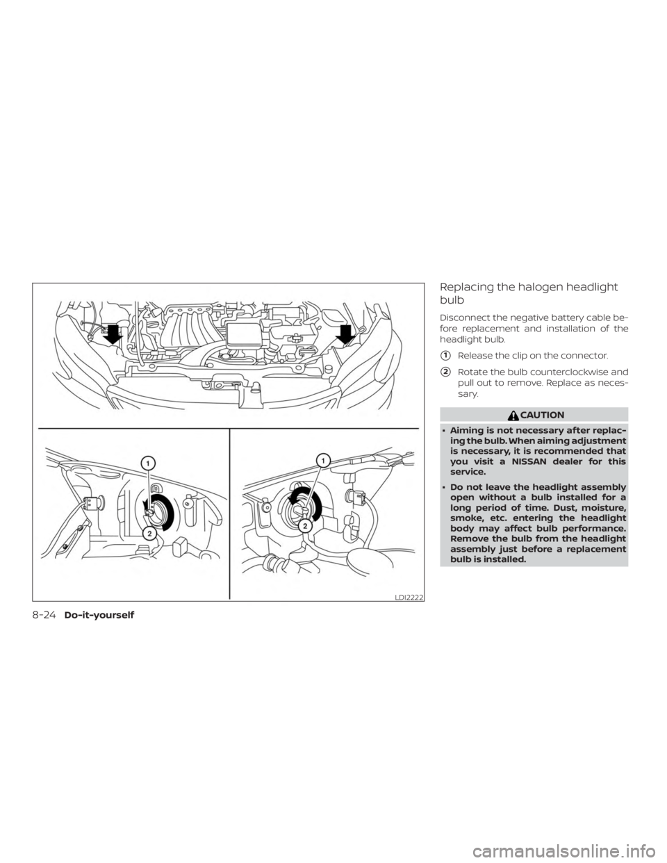
Replacing the halogen headlight
bulb
Disconnect the negative battery cable be-
fore replacement and installation of the
headlight bulb.
�1Release the clip on the connector.
�2Rotate the bulb counterclockwise and
pull out to remove. Replace as neces-
sary.
Page 235 of 300

∙ Only touch the base when handlingthe bulb. Never touch the glass enve-
lope. Touching the glass could signifi-
cantly affect bulb life and/or head-
light performance.
∙ High pressure halogen gas is sealed inside the halogen bulb. The bulb may
break if the glass envelope is
scratched or the bulb is dropped.
∙ Use the same number and wattage as shown in the chart.
Fog may temporarily form inside the lens
of the exterior lights in the rain or in a car
wash. A temperature difference between
the inside and the outside of the lens
causes the fog. This is not a malfunction. If
large drops of water collect inside the lens,
it is recommended that you visit a NISSAN
dealer for this service.
Aiming the headlights
The headlights on your vehicle are properly
aimed at the assembly plant. If your vehicle
has been in a collision, the alignment of
your headlights should be checked. It is
recommended that you visit a NISSAN
dealer for this service. Vertical aim adjustment
NOTE:
Due to a maximum load condition of the
vehicle, headlight aiming adjustment
may be necessary. Please perform the
following procedure:
1. Park the vehicle directly in front of a wallor screen on a level surface, approxi-
mately 25 feet (7.6 meters) away.
∙
�18 feet (2.4 meters)
∙
�2Center height of headlight to ground
∙
�325 feet (7.6 meters)
∙
�4Horizontal reference line
2. Measure the height from the center of the headlight to the ground and mark
an 8 foot (2.4 meter) horizontal refer-
ence line on the vertical wall or screen
at this height (a piece of masking tape
works well).
Page 241 of 300
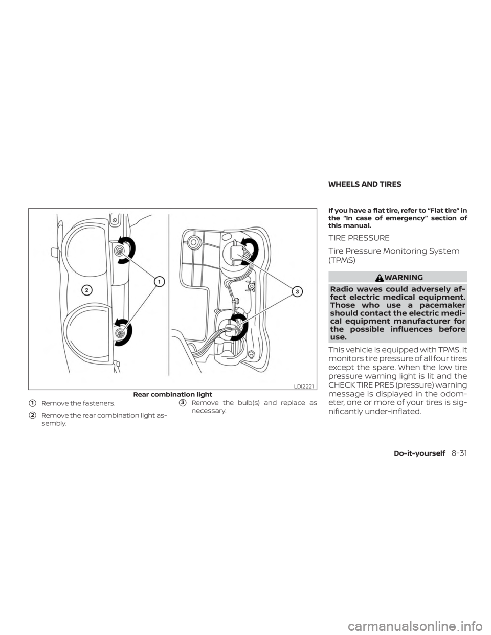
�1Remove the fasteners.
�2Remove the rear combination light as-
sembly.
�3Remove the bulb(s) and replace as
necessary. If you have a flat tire, refer to “Flat tire” in
the “In case of emergency ” section of
this manual.
TIRE PRESSURE
Tire Pressure Monitoring System
(TPMS)
Page 242 of 300
. Also, this system
may not detect a sudden drop in tire
pressure (for example a flat tire while
driving).
For ad")
The TPMS will activate only when the
vehicle is driven at speeds above
16 mph (25 km/h). Also, this system
may not detect a sudden drop in tire
pressure (for example a flat tire while
driving).
For additional information, refer to
“Warning lights, indicator lights and
audible reminders” in the “Instru-
ments and controls” section, “Tire
Pressure Monitoring System (TPMS)”
in the “Starting and driving” section,
and “Flat tire” in the “In case of emer-
gency” section of this manual.
Tire inflation pressure
Check the tire pressures (including
the spare) of ten and always prior to
long distance trips. The recom-
mended tire pressure specifications
are shown on the F.M.V.S.S./C.M.V.S.S.
certification label or the Tire and
Loading Information label under the
“Cold Tire Pressure” heading. The Tire
and Loading Information label is af-
fixed to the driver side center pillar.Tire pressures should be checked
regularly because:
∙ Most tires naturally lose air over time.
∙ Tires can lose air suddenly when driven over potholes or other ob-
jects or if the vehicle strikes a
curb while parking.
The tire pressures should be
checked when the tires are cold. The
tires are considered COLD af ter the
vehicle has been parked for 3 or
more hours, or driven less than 1 mile
(1.6 km) at moderate speeds.
Incorrect tire pressure, including
under inflation, may adversely af-
fect tire life and vehicle handling.
Page 251 of 300

∙ When replacing a wheel without theTPMS, such as the spare tire, the TPMS
will not function and the low tire pres-
sure warning light will flash for ap-
proximately 1 minute. The light will re-
main on af ter 1 minute. Have your
tires replaced and/or TPMS system
reset as soon as possible. It is recom-
mended that you visit a NISSAN dealer
for this service.
∙ The TPMS sensor may be damaged if it is not handled correctly. Be careful
when handling the TPMS sensor.
∙ When replacing the TPMS sensor, the ID registration may be required. It is
recommended that you visit a NISSAN
dealer for ID registration.
∙ Do not use a valve stem cap that is not specified by NISSAN. The valve stem
cap may become stuck.
∙ Be sure that the valve stem caps are correctly fitted. Otherwise the valve
may be clogged up with dirt and
cause a malfunction or loss of
pressure.
∙ Replacing tires with those not origi- nally specified by NISSAN could affect
the proper operation of the TPMS. ∙ Do not install a damaged or deformed
wheel or tire even if it has been re-
paired. Such wheels or tires could
have structural damage and could fail
without warning.
∙ The use of retread tires is not recommended.
∙ For additional information regarding tires, refer to “Important Tire Safety
Information” (US) or “Tire Safety Infor-
mation” (Canada) in the Warranty In-
formation Booklet.
Wheel balance
Unbalanced wheels may affect vehicle
handling and tire life. Even with regular use,
wheels can get out of balance. Therefore,
they should be balanced as required.
Wheel balance service should be per-
formed with the wheels off the vehicle.
Spin balancing the wheels on the vehicle
could lead to mechanical damage. ∙
For additional information regarding
tires, refer to “Important Tire Safety
Information” (US) or “Tire Safety In-
formation” (Canada) in the Warranty
Information Booklet.
Care of wheels
∙ Wash the wheels when washing the ve- hicle to maintain their appearance.
∙ Clean the inner side of the wheels when the wheel is changed or the underside
of the vehicle is washed.
∙ Do not use abrasive cleaners when washing the wheels.
∙ Inspect wheel rims regularly for dents or corrosion. Such damage may cause
loss of pressure or poor seal at the tire
bead.
∙ NISSAN recommends waxing the road wheels to protect against road salt in
areas where it is used during winter.
Do-it-yourself8-41
Page 279 of 300
Use the following steps to mount the front
license plate:
Before mounting the license plate, confirm
that the following parts are enclosed in the
plastic bag:∙ License plate bracket
∙ License plate screws x 2
∙ Screw grommets x 2
1. Hold the license plate bracket
�1and
make a shallow hole in the bumper fas-
cia using a drill. To avoid damaging the
area behind the fascia, apply only light
pressure to the drill.
2. Insert the grommets
�2into the holes
in the bumper fascia.
3. Mount the license plate bracket using the two screws
�3.
4. Mount the front license plate.