Page 17 of 559
1. Rear window and outside mirror(if so equipped) defroster switch
(P. 2-44)
2. Trunk lid (P. 3-23)
3. Sonar sensors (if so equipped)
(P. 5-175)
4. Rearview camera (P. 4-3)
5. Replacing bulbs (P. 8-25)
6. Fuel-filler cap (P. 3-25) Fuel recommendation (P. 10-2)
Fuel-filler door (P. 3-25)
7. Child safety rear door lock (P. 3-4)
Refer to the page number indicated in
parentheses for operating details.
LIC4027
EXTERIOR REAR
0-4Illustrated table of contents
Page 20 of 559

9. Front passenger supplemental airbag (P. 1-46)
10. Passenger supplemental knee
airbag (P. 1-46)
11.. Glove box (P. 2-58)
12. Front passenger air bag status
light (P. 1-46)
Hazard warning flasher switch
(P. 6-2)
13. Power outlet (P. 2-56) USB connection port
(if so equipped) (P. 4-2, 4-42)
Aux jack*
14. Cup holders (P. 2-58)
15 Shif t lever (P. 5-18)
16. Electronic parking brake switch
(if so equipped) (P. 5-25)
Automatic brake hold switch
(if so equipped) (P. 5-25)
17. Push-button ignition switch
(P. 5-13) 18. Cruise control switches
(if so equipped) (P. 5-63)
Intelligent Cruise Control (ICC)
switches (if so equipped) (P. 5-66)
Bluetooth® Hands-free Phone
System*
ProPILOT Assist Switch
(if so equipped) (P. 5-90)
19. Driver supplemental knee airbag
(P. 1-46)
20. Hood release (P. 3-22) Fuel-filler door release (P. 3-25)
Tilt/telescopic steering wheel
controls (P. 3-28)
21. Trip computer reset switch (P. 2-4) Instrument brightness control
(P. 2-45)
Steering assist switch
(for vehicles with ProPILOT Assist)
(if so equipped) (P. 2-54)
Trunk opener (P. 3-23)
*: For additional information, refer to the
separate NissanConnect® Owner’s Manual.
Refer to the page number indicated in
parentheses for operating details.
Illustrated table of contents0-7
Page 30 of 559
Seat lif ter (driver’s seat)
Move the switch as shown to adjust the
angle and height of the seat cushion.
Lumbar support (if so equipped
for driver’s seat)
The lumbar support feature provides ad-
justable lower back support to the driver.
Push the switch as shown to adjust the
seat lumbar area.
FOLDING REAR SEAT
Interior trunk access
LRS2636LRS2270
LRS3156
Safety—Seats, seat belts and supplemental restraint system1-5
Page 31 of 559

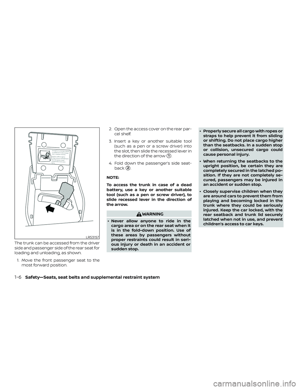
The trunk can be accessed from the driver
side and passenger side of the rear seat for
loading and unloading, as shown.1. Move the front passenger seat to the most forward position. 2. Open the access cover on the rear par-
cel shelf.
3. Insert a key or another suitable tool (such as a pen or a screw driver) into
the slot, then slide the recessed lever in
the direction of the arrow
�1.
4. Fold down the passenger’s side seat- back
�2.
NOTE:
To access the trunk in case of a dead
battery, use a key or another suitable
tool (such as a pen or screw driver), to
slide recessed lever in the direction of
the arrow.
WARNING
∙ Never allow anyone to ride in the cargo area or on the rear seat when it
is in the fold-down position. Use of
these areas by passengers without
proper restraints could result in seri-
ous injury or death in an accident or
sudden stop. ∙ Properly secure all cargo with ropes or
straps to help prevent it from sliding
or shif ting. Do not place cargo higher
than the seatbacks. In a sudden stop
or collision, unsecured cargo could
cause personal injury.
∙ When returning the seatbacks to the upright position, be certain they are
completely secured in the latched po-
sition. If they are not completely se-
cured, passengers may be injured in
an accident or sudden stop.
∙ Closely supervise children when they are around cars to prevent them from
playing and becoming locked in the
trunk where they could be seriously
injured. Keep the car locked, with the
rear seatback and trunk lid securely
latched when not in use, and prevent
children’s access to car keys.
LRS3157
1-6Safety—Seats, seat belts and supplemental restraint system
Page 32 of 559

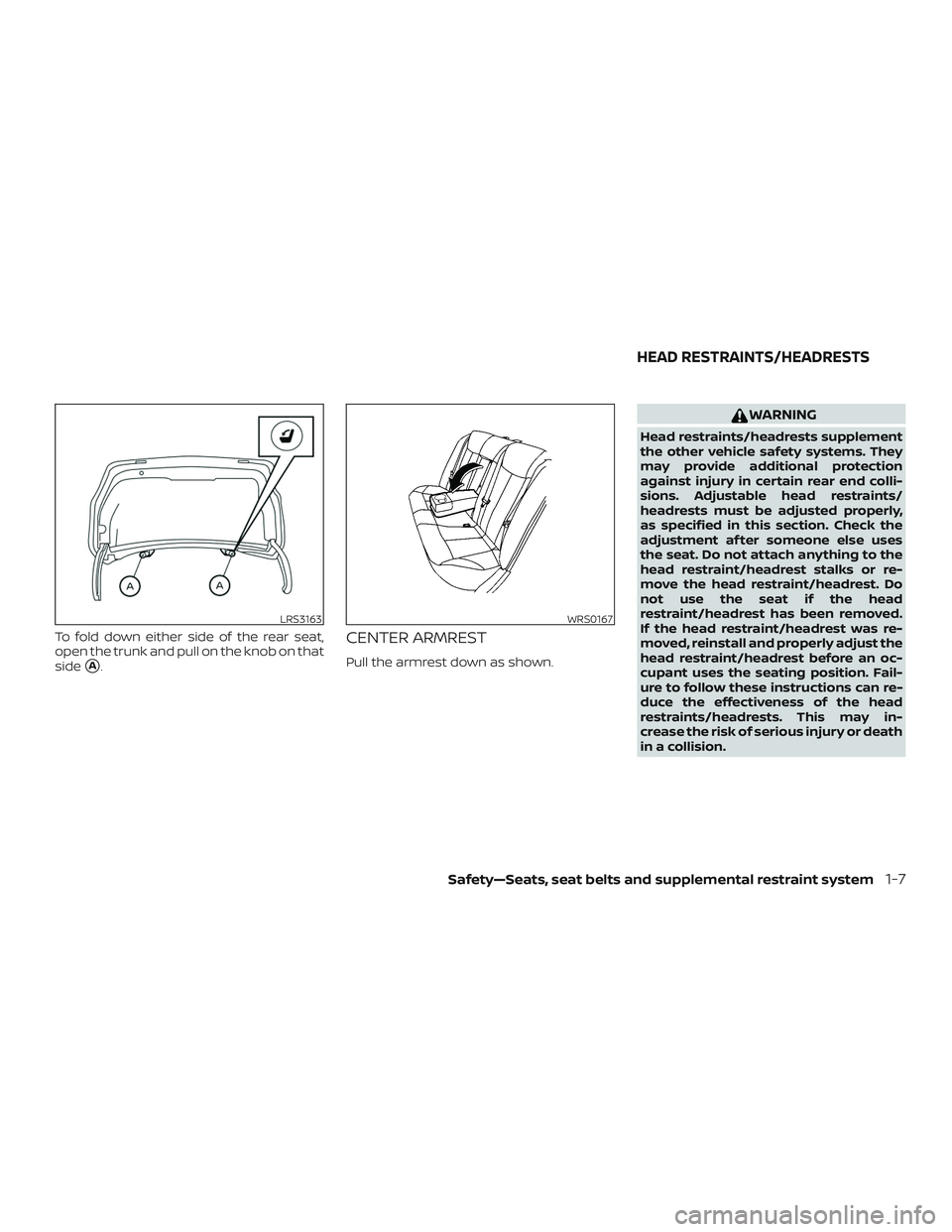
To fold down either side of the rear seat,
open the trunk and pull on the knob on that
side
�A.
CENTER ARMREST
Pull the armrest down as shown.
WARNING
Head restraints/headrests supplement
the other vehicle safety systems. They
may provide additional protection
against injury in certain rear end colli-
sions. Adjustable head restraints/
headrests must be adjusted properly,
as specified in this section. Check the
adjustment af ter someone else uses
the seat. Do not attach anything to the
head restraint/headrest stalks or re-
move the head restraint/headrest. Do
not use the seat if the head
restraint/headrest has been removed.
If the head restraint/headrest was re-
moved, reinstall and properly adjust the
head restraint/headrest before an oc-
cupant uses the seating position. Fail-
ure to follow these instructions can re-
duce the effectiveness of the head
restraints/headrests. This may in-
crease the risk of serious injury or death
in a collision.
LRS3163WRS0167
HEAD RESTRAINTS/HEADRESTS
Safety—Seats, seat belts and supplemental restraint system1-7
Page 96 of 559

Front-door pockets.......................... 2-58
Seatback pockets ........................... 2-58
Glovebox.................................... 2-59
Console box ................................. 2-59
Overhead sunglasses storage ...............2-59
Cup holders ................................. 2-60
Windows ....................................... 2-61
Power windows ............................. 2-61
Moonroof (if so equipped) ......................2-64
Power moonroof ............................ 2-64
Interior lights ................................... 2-66
Map lights ................................... 2-66
Personal lights .............................. 2-67Trunk light
...................................... 2-67
HomeLink® Universal Transceiver
(if so equipped) ................................. 2-67
Programming HomeLink® ...................2-68
Programming HomeLink® for Canadian
customers and gate openers ................2-69
Operating the HomeLink® Universal
Transceiver .................................. 2-70
Programming trouble-diagnosis ............2-70
Clearing the programmed information ......2-71
Reprogramming a single HomeLink®
button....................................... 2-71
If your vehicle is stolen ....................... 2-71
Page 98 of 559

10. Passenger supplemental kneeairbag (P. 1-46)
11.. Glove box (P. 2-58)
12. Front passenger air bag status
light (P. 1-46)
Hazard warning flasher switch
(P. 6-2)
13. Power outlet (P. 2-56) USB connection port
(if so equipped) (P. 4-2, 4-42)
Aux jack*
14. Cup holders (P. 2-58)
15 Shif t lever (P. 5-18)
16. Electronic parking brake switch
(if so equipped) (P. 5-25)
Automatic brake hold switch
(if so equipped) (P. 5-25)
17. Push-button ignition switch
(P. 5-13)
18. Cruise control switches
(if so equipped) (P. 5-63)
Intelligent Cruise Control (ICC)
switches (if so equipped) (P. 5-66)
Bluetooth® Hands-free Phone
System*
ProPILOT Assist Switch (if so
equipped) (P. 5-90) 19. Driver supplemental knee airbag
(P. 1-46)
20. Hood release (P. 3-22) Fuel-filler door release (P. 3-25)
Tilt/telescopic steering wheel
controls (P. 3-28)
21. Trip computer reset switch (P. 2-4) Instrument brightness control
(P. 2-45)
Steering assist switch (for vehicles
with ProPILOT Assist) (if so
equipped) (P. 2-54)
Trunk opener (P. 3-23)
*: For additional information, refer to the
separate NissanConnect® Owner’s Manual.
Refer to the page number indicated in
parentheses for operating details.
Instruments and controls2-3
Page 109 of 559

∙ When replacing a wheel without theTPMS such as the spare tire, the TPMS
will not function and the low tire pres-
sure warning light will flash for ap-
proximately 1 minute. The light will re-
main on af ter 1 minute. Have your
tires replaced and/or TPMS system
reset as soon as possible. It is recom-
mended that you visit a NISSAN dealer
for these services.
∙ Replacing tires with those not origi- nally specified by NISSAN could affect
the proper operation of the TPMS.
CAUTION
∙ The TPMS is not a substitute for theregular tire pressure check. Be sure to
check the tire pressure regularly.
∙ If the vehicle is being driven at speeds of less than 16 mph (25 km/h), the
TPMS may not operate correctly.
∙ Be sure to install the specified size of tires to the four wheels correctly.
Master warning light
When the ignition is in the ON position, the
master warning light illuminates if any of
the following are displayed on the vehicle
information display.
∙ No key warning
∙ Low windshield-washer fluid warning
∙ Parking brake release warning
∙ Door/trunk open warning
∙ Loose fuel cap
∙ Low tire pressure warning
Power steering warninglight
WARNING
∙ If the engine is not running or is turned off while driving, the power as-
sist for the steering will not work.
Steering will be harder to operate. ∙ When the power steering warning
light illuminates with the engine run-
ning, there will be no power assist for
the steering. You will still have control
of the vehicle, but the steering will be
harder to operate. Have the power
steering system checked. It is recom-
mended that you visit a NISSAN dealer
for this service.
When the ignition switch is placed in the ON
position, the power steering warning light
illuminates. Af ter starting the engine, the
power steering warning light turns off. This
indicates the power steering is operational.
If the power steering warning light illumi-
nates while the engine is running, it may
indicate the power steering is not function-
ing properly and may need servicing. Have
the power steering checked. It is recom-
mended that you visit a NISSAN dealer for
this service.
When the power steering warning light illu-
minates with the engine running, there will
be no power assist for the steering, but you
will still have control of the vehicle. At this
time, greater steering effort is required to
operate the steering wheel, especially in
sharp turns and at low speeds.
2-14Instruments and controls