Page 152 of 559
The extended storage switch is used when
shipping the vehicle. It is located in the fuse
panel to the lef t of the steering wheel on
the instrument panel. If any electrical
equipment does not operate, ensure the
extended storage switch is pushed fully in
place, as shown.
LIC4040
Pulled position
LIC3266
Pushed position
LIC3268
EXTENDED STORAGE SWITCH
Instruments and controls2-57
Page 167 of 559

3 Pre-driving checks and adjustments
Keys.............................................3-2NISSAN Intelligent Key® .......................3-2
NISSAN Vehicle Immobilizer System
keys..........................................3-4
Doors ...........................................3-4
Locking with key ..............................3-5
Locking with inside lock knob .................3-6
Locking with power door lock switch .........3-6
Automatic door locks (if so equipped) ........3-6
Child safety rear door lock .................... 3-7
NISSAN Intelligent Key® .......................... 3-7
Operating range ..............................3-9
Door locks/unlocks precaution ...............3-9
NISSAN Intelligent Key® operation ............3-10
How to use the remote keyless entry
function ..................................... 3-14
Warning signals ............................. 3-16
Troubleshooting guide ......................3-17
Remote Engine Start ........................... 3-19
Remote Engine Start operating range .......3-19
Remote starting the vehicle .................3-20
Extending engine run time ..................3-20Canceling a Remote Engine Start
............3-20
Conditions the Remote Engine Start will
notwork .................................... 3-21
Hood ........................................... 3-22
Trunk lid ........................................ 3-23
Opener operation ........................... 3-23
Interior trunk lid release .....................3-24
Interior trunk access ........................ 3-24
Fuel-filler door .................................. 3-25
Opener operation ........................... 3-25
Fuel-filler cap ................................ 3-25
Steering wheel ................................. 3-28
Tilt operation ................................ 3-28
Telescopic operation ........................ 3-28
Sun visors ...................................... 3-29
Vanity mirrors ............................... 3-29
Mirrors ......................................... 3-30
Manual anti-glare rearview mirror
(if so equipped) .............................. 3-30
Automatic anti-glare rearview mirror
(if so equipped) .............................. 3-30
Outside
mirrors............................. 3-31
Page 194 of 559

To remove the fuel-filler cap:1. Turn the fuel-filler cap counterclock- wise to remove.
2. Put the fuel-filler cap on the cap holder
�1while refueling.
To install the fuel-filler cap: 1. Insert the fuel-filler cap straight into the fuel-filler tube.
2. Turn the fuel-filler cap clockwise until a single click is heard.
Loose Fuel Cap warning
The Loose Fuel Cap warning message will
be displayed in the vehicle information dis-
play when the fuel-filler cap is not tight-
ened correctly af ter the vehicle has been
refueled. It may take a few driving trips for
the message to be displayed. To turn off
the warning, perform the following:
1. Remove and install the fuel-filler cap as soon as possible. For additional infor-
mation, refer to “Fuel-filler cap” in this
section. 2. Tighten the fuel-filler cap until it clicks.
3. Press the OK button on the steering
wheel for about 1 second to turn off the
Loose Fuel Cap warning af ter tighten-
ing the fuel-filler cap.
LPD2870LPD3029
Pre-driving checks and adjustments3-27
Page 195 of 559

WARNING
∙ Do not adjust the steering wheel whiledriving. You could lose control of your
vehicle and cause an accident.
∙ Do not adjust the steering wheel any closer to you than is necessary for
proper steering operation and com-
fort. The driver’s air bag inflates with
great force. If you are unrestrained,
leaning forward, sitting sideways or
out of position in any way, you are at
greater risk of injury or death in a
crash. You may also receive serious or
fatal injuries from the air bag if you
are up against it when it inflates. Al-
ways sit back against the seatback
and as far away as practical from the
steering wheel. Always use the seat
belts.
TILT OPERATION
Pull the lock lever down and hold on until
the end of the stroke
�1and adjust the
steering wheel up or down
�2to the de-
sired position.
Push the lock lever up
�1firmly and hold on
until end of stroke to lock the steering
wheel in place.
TELESCOPIC OPERATION
Pull the lock lever down�1and adjust the
steering wheel forward or backward
�3to
the desired position.
Push the lock lever up
�1firmly and hold on
until end of stroke to lock the steering
wheel in place.
LPD2871
STEERING WHEEL
3-28Pre-driving checks and adjustments
Page 208 of 559

HOW TO READ THE DISPLAYED
LINES
Guiding lines which indicate the vehicle
width and distances to objects with refer-
ence to the vehicle body line
�Aare dis-
played on the monitor.
Distance guide lines
Indicate distances from the vehicle body.
∙ Red line
�1: approx. 1.5 f t (0.5 m)
∙ Yellow line
�2: approx. 3 f t (1 m)
∙ Green line
�3: approx. 7 f t (2 m) Vehicle width guide lines
�4
Indicate the vehicle width when backing
up.
Predicted course lines
�5
Indicate the predicted course when back-
ing up. The predicted course lines will be
displayed on the monitor when the shif t
lever is in the R (Reverse) position and the
steering wheel is turned. The predicted
course lines will move depending on how
much the steering wheel is turned and will
not be displayed while the steering wheel is
in the straight-ahead position.
The vehicle width guide lines and the width
of the predicted course lines are wider than
the actual width and course.
DIFFERENCE BETWEEN PREDICTED
AND ACTUAL DISTANCES
The displayed guidelines and their loca-
tions on the ground are for approximate
reference only. Objects on uphill or downhill
surfaces or projecting objects will be actu-
ally located at distances different from
those displayed in the monitor relative to
the guidelines (refer to illustrations). When
in doubt, turn around and view the objects as you are backing up, or park and exit the
vehicle to view the positioning of objects
behind the vehicle.
LHA4805
Monitor, climate, audio, phone and voice recognition systems4-5
Page 210 of 559

Backing up behind a projecting
object
The position�Cis shown farther than the
position
�Bin the display. However, the po-
sition
�Cis actually at the same distance as
the position
�A. The vehicle may hit the object when backing up to the position
�A
if the object projects over the actual back-
ing up course.
HOW TO PARK WITH PREDICTED
COURSE LINES
WARNING
∙ If the tires are replaced with different
sized tires, the predicted course lines
may be displayed incorrectly.
∙ On a snow-covered or slippery road, there may be a difference between
the predicted course line and the ac-
tual course line.
∙ If the battery is disconnected or be- comes discharged, the predicted
course lines may be displayed incor-
rectly. If this occurs, please perform
the following procedures:
– Turn the steering wheel from lock to lock while the engine is running.
– Drive the vehicle on a straight road for more than 5 minutes.
∙ When the steering wheel is turned with the ignition switch in the ACC po-
sition, the predicted course lines may
be displayed incorrectly. 1. Visually check that the parking space is
safe before parking your vehicle.
2. The rear view of the vehicle is displayed on the screen
�Awhen the shif t lever is
moved to the R (Reverse) position.
LHA5179LHA5043
Monitor, climate, audio, phone and voice recognition systems4-7
Page 211 of 559
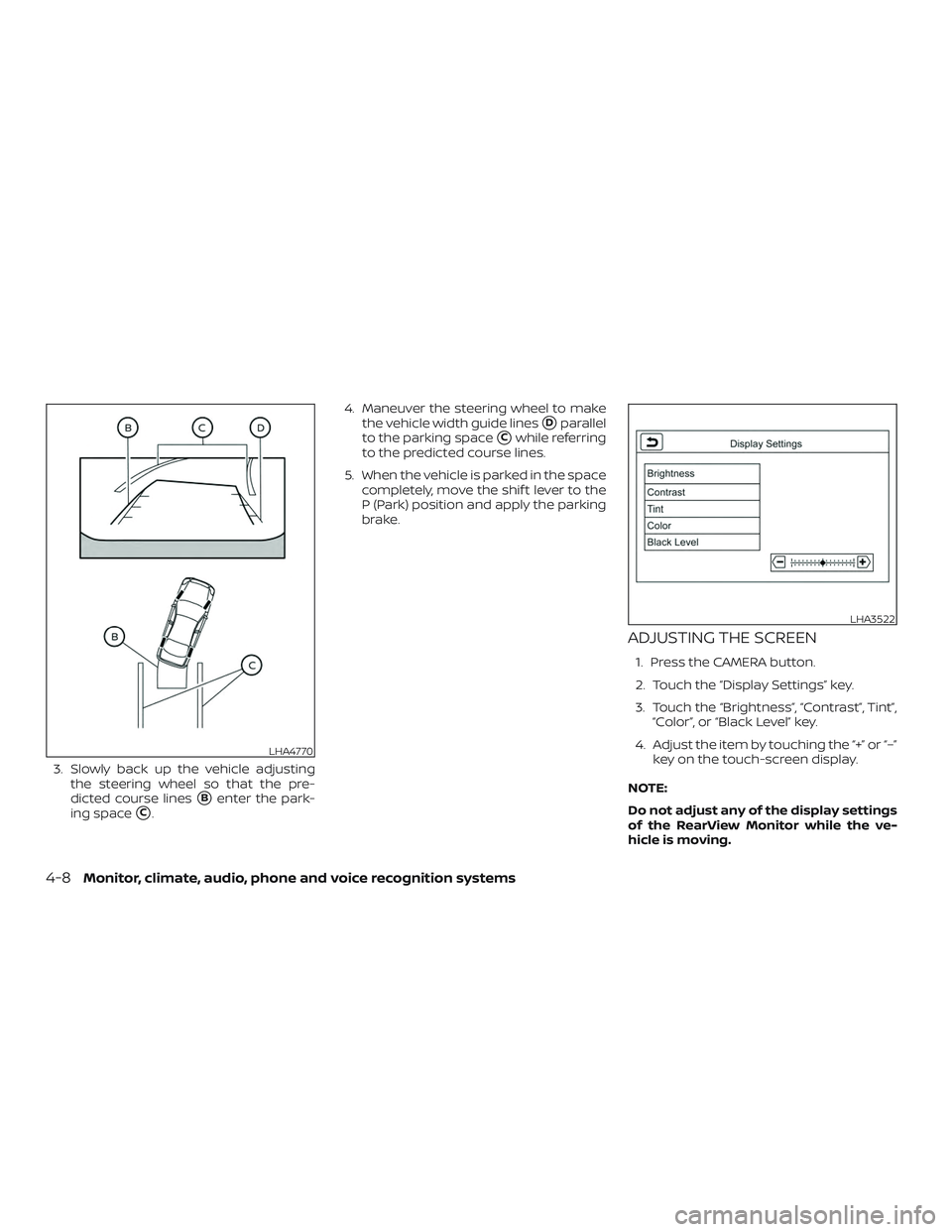
3. Slowly back up the vehicle adjustingthe steering wheel so that the pre-
dicted course lines
�Benter the park-
ing space
�C. 4. Maneuver the steering wheel to make
the vehicle width guide lines
�Dparallel
to the parking space
�Cwhile referring
to the predicted course lines.
5. When the vehicle is parked in the space completely, move the shif t lever to the
P (Park) position and apply the parking
brake.
ADJUSTING THE SCREEN
1. Press the CAMERA button.
2. Touch the “Display Settings” key.
3. Touch the “Brightness”, “Contrast”, Tint”,“Color”, or “Black Level” key.
4. Adjust the item by touching the “+” or “–” key on the touch-screen display.
NOTE:
Do not adjust any of the display settings
of the RearView Monitor while the ve-
hicle is moving.
LHA4770
LHA3522
4-8Monitor, climate, audio, phone and voice recognition systems
Page 215 of 559

WARNING
Failure to follow the warnings and in-
structions for the proper use of the In-
telligent Around View Monitor system
could result in serious injury or death
∙ The Intelligent Around View Monitor isa convenience feature and is not a
substitute for proper vehicle opera-
tion because it has areas where ob-
jects cannot be viewed. The four cor-
ners of the vehicle in particular, are
areas where objects do not always
appear in the bird’s-eye, front, or rear
views. Always check your surround-
ings to be sure that it is safe to move
before operating the vehicle. Always
operate the vehicle slowly.
∙ The driver is always responsible for safety during parking and other
maneuvers.
CAUTION
Do not scratch the camera lens when
cleaning dirt or snow from the front of
the camera. The Intelligent Around View Monitor sys-
tem is designed as an aid to the driver in
situations such as slot parking or parallel
parking.
The monitor displays various views of the
position of the vehicle in a split screen for-
mat. Not all views are available at all times.
Available views:
∙ Front View An approximately 150–degree view of
the front of the vehicle.
∙ Rear View An approximately 150–degree view of
the rear of the vehicle.
∙ Bird’s-Eye View The surrounding views of the vehicle
from above.
∙ Front-Side View The view around and ahead of the front
passenger’s side wheel.
∙ Full Screen Rear View The view to the rear of the vehicle
(which is a little wider than the standard
Rear View). To display the multiple views, the Intelligent
Around View Monitor system uses cam-
eras located in the front grille, on the vehi-
cle’s outside mirrors and one just above
the vehicle’s license plate
�1.
INTELLIGENT AROUND VIEW
MONITOR SYSTEM OPERATION
With the ignition switch in the ON position,
move the shif t lever to the R (Reverse) po-
sition or press the CAMERA button to oper-
ate the Intelligent Around View Monitor.
LHA4802
4-12Monitor, climate, audio, phone and voice recognition systems