2020 NISSAN 370Z check engine light
[x] Cancel search: check engine lightPage 309 of 455

.Make sure the area around the vehicle
is clear.
. Check fluid levels such as engine oil,
coolant, brake fluid and window
washer fluid as frequently as possible,
or at least whenever you refuel.
. Check that all windows and lights are
clean.
. Visually inspect tires for their appear-
ance and condition. Also check tires
for proper inflation.
. Lock all doors.
. Position seat and adjust head re-
straints.
. Adjust inside and outside mirrors.
. Fasten seat belts and ask all passen-
gers to do likewise.
. Check the operation of warning lights
when the ignition switch is pushed to
the ON position. (See “Warning lights,
indicator lights and audible remin-
ders” (P.2-10).) 1. Apply the parking brake.
2.
Automatic Transmission (AT) model:
Move the shift lever to the P (Park) or N
(Neutral) position. (P is recommended.)
The starter is designed not to operate
unless the shift lever is in either of the
above positions.
Manual Transmission (MT) model:
Move the shift lever to the N (Neutral)
position. Depress the clutch pedal fully
to the floor.
The starter is designed not to operate
unless the clutch pedal is fully de-
pressed.
The Intelligent Key must be carried
when operating the ignition switch.
3. Push the ignition switch to the ON position. Firmly depress the brake
pedal (AT model) or the clutch pedal
(MT model) and push the ignition
switch to start the engine.
To start the engine immediately, push
and release the ignition switch while
depressing the brake pedal or the
clutch pedal with the ignition switch
in any position.
.If the engine is very hard to start inextremely cold weather or when
restarting, depress the accelerator
pedal a little (approximately 1/3 to the floor) and while holding, crank
the engine. Release the accelerator
pedal when the engine starts.
.If the engine is very hard to start
because it is flooded, depress the
accelerator pedal all the way to the
floor and hold it. Push the ignition
switch to the ON position to start
cranking the engine. After 5 or 6
seconds, stop cranking by pushing
the ignition switch to OFF. After
cranking the engine, release the
accelerator pedal. Crank the engine
with your foot off the accelerator
pedal by depressing the brake
pedal and pushing the push-button
ignition switch to start the engine.
If the engine starts, but fails to run,
repeat the above procedure.
CAUTION
Do not operate the starter for more
than 15 seconds at a time. If the
engine does not start, push the
ignition switch to OFF and wait 10
seconds before cranking again,
otherwise the starter could be da-
maged.
Starting and driving5-11
BEFORE STARTING THE ENGINE STARTING THE ENGINE
Page 314 of 455

5-16Starting and driving
SSD0832
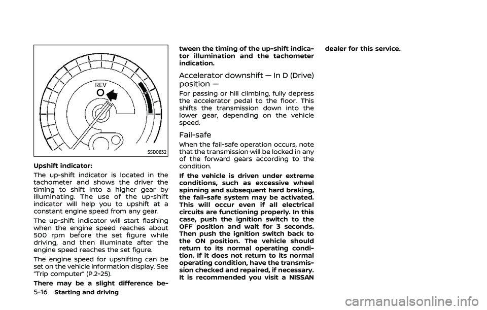
Upshift indicator:
The up-shift indicator is located in the
tachometer and shows the driver the
timing to shift into a higher gear by
illuminating. The use of the up-shift
indicator will help you to upshift at a
constant engine speed from any gear.
The up-shift indicator will start flashing
when the engine speed reaches about
500 rpm before the set figure while
driving, and then illuminate after the
engine speed reaches the set figure.
The engine speed for upshifting can be
set on the vehicle information display. See
“Trip computer” (P.2-25).
There may be a slight difference be-tween the timing of the up-shift indica-
tor illumination and the tachometer
indication.
Accelerator downshift — In D (Drive)
position —
For passing or hill climbing, fully depress
the accelerator pedal to the floor. This
shifts the transmission down into the
lower gear, depending on the vehicle
speed.
Fail-safe
When the fail-safe operation occurs, note
that the transmission will be locked in any
of the forward gears according to the
condition.
If the vehicle is driven under extreme
conditions, such as excessive wheel
spinning and subsequent hard braking,
the fail-safe system may be activated.
This will occur even if all electrical
circuits are functioning properly. In this
case, push the ignition switch to the
OFF position and wait for 3 seconds.
Then push the ignition switch back to
the ON position. The vehicle should
return to its normal operating condi-
tion. If it does not return to its normal
operating condition, have the transmis-
sion checked and repaired, if necessary.
It is recommended you visit a NISSAN
dealer for this service.
Page 315 of 455

SSD0829
Shift lock release
If the battery charge is low or discharged,
the shift lever may not be moved from the
P (Park) position even with the brake
pedal depressed and the shift lever but-
ton pushed.
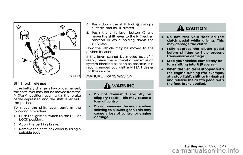
To move the shift lever, perform the
following procedure:
1. Push the ignition switch to the OFF orLOCK position.
2. Apply the parking brake.
3. Remove the shift lock cover
using a
suitable tool. 4. Push down the shift lock
using a
suitable tool as illustrated.
5. Push the shift lever button
and
move the shift lever to the N (Neutral)
position
while holding down the
shift lock.
Now the vehicle may be moved to the
desired location.
If the lever cannot be moved out of P
(Park), have the automatic transmission
system checked as soon as possible. It is
recommended you visit a NISSAN dealer
for this service.
MANUAL TRANSMISSION
WARNING
. Do not downshift abruptly on
slippery roads. This may cause a
loss of control.
. Do not over-rev the engine when
shifting to a lower gear. This may
cause a loss of control or engine
damage.
CAUTION
.Do not rest your foot on the
clutch pedal while driving. This
may damage the clutch.
. Fully depress the clutch pedal
before shifting to help prevent
transmission damage.
. Stop your vehicle completely be-
fore shifting into R (Reverse).
. When the vehicle is stopped with
the engine running (for example,
at a stop light), shift to N (Neutral)
and release the clutch pedal with
the foot brake applied.
Starting and driving5-17
Page 320 of 455

5-22Starting and driving
SPA2110
To apply:Pull the parking brake lever up.
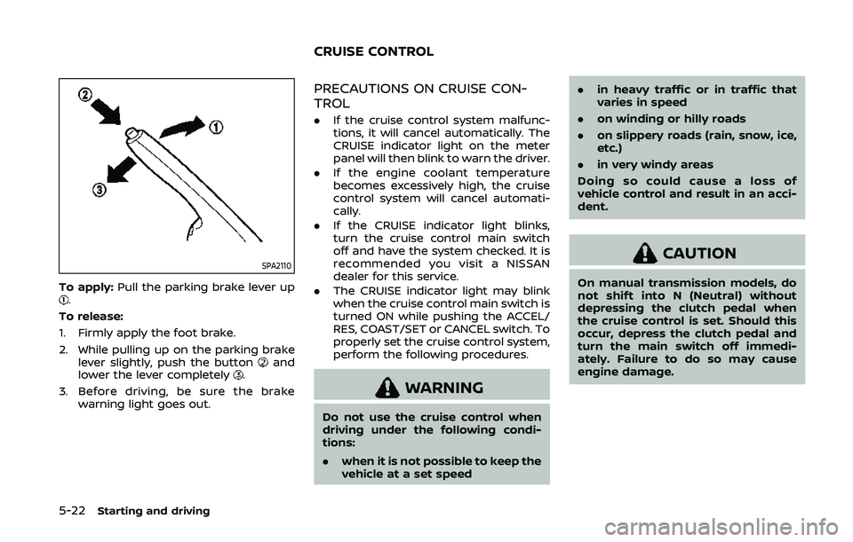
To release:
1. Firmly apply the foot brake.
2. While pulling up on the parking brake lever slightly, push the button
and
lower the lever completely.
3. Before driving, be sure the brake warning light goes out.
PRECAUTIONS ON CRUISE CON-
TROL
.If the cruise control system malfunc-
tions, it will cancel automatically. The
CRUISE indicator light on the meter
panel will then blink to warn the driver.
. If the engine coolant temperature
becomes excessively high, the cruise
control system will cancel automati-
cally.
. If the CRUISE indicator light blinks,
turn the cruise control main switch
off and have the system checked. It is
recommended you visit a NISSAN
dealer for this service.
. The CRUISE indicator light may blink
when the cruise control main switch is
turned ON while pushing the ACCEL/
RES, COAST/SET or CANCEL switch. To
properly set the cruise control system,
perform the following procedures.
WARNING
Do not use the cruise control when
driving under the following condi-
tions:
.when it is not possible to keep the
vehicle at a set speed .
in heavy traffic or in traffic that
varies in speed
. on winding or hilly roads
. on slippery roads (rain, snow, ice,
etc.)
. in very windy areas
Doing so could cause a loss of
vehicle control and result in an acci-
dent.
CAUTION
On manual transmission models, do
not shift into N (Neutral) without
depressing the clutch pedal when
the cruise control is set. Should this
occur, depress the clutch pedal and
turn the main switch off immedi-
ately. Failure to do so may cause
engine damage.
CRUISE CONTROL
Page 327 of 455

faces even with ABS. Stopping
distances may also be longer on
rough, gravel or snow covered
roads, or if you are using tire
chains. Always maintain a safe
distance from the vehicle in front
of you. Ultimately, the driver is
responsible for safety.
. Tire type and condition may also
affect braking effectiveness.
— When replacing tires, install
the specified size of tires on
all four wheels.
— When installing a spare tire, make sure that it is the proper
size and type as specified on
the Tire and Loading Informa-
tion label. See “Tire and Load-
ing Information label” (P.10-
14) of this manual.
— For detailed information, see “Wheels and tires” (P.8-26) of
this manual.
The Anti-lock Braking System (ABS) con-
trols the brakes so the wheels do not lock
during hard braking or when braking on
slippery surfaces. The system detects the
rotation speed at each wheel and varies
the brake fluid pressure to prevent each
wheel from locking and sliding. By pre- venting each wheel from locking, the
system helps the driver maintain steering
control and helps to minimize swerving
and spinning on slippery surfaces.
Using the system
Depress the brake pedal and hold it down.
Depress the brake pedal with firm steady
pressure, but do not pump the brakes.
The ABS will operate to prevent the
wheels from locking up. Steer the vehicle
to avoid obstacles.
WARNING
Do not pump the brake pedal. Doing
so may result in increased stopping
distances.
Self-test feature
The ABS includes electronic sensors, elec-
tric pumps, hydraulic solenoids and a
computer. The computer has a built-in
diagnostic feature that tests the system
each time you start the engine and move
the vehicle at a low speed in forward or
reverse. When the self-test occurs, you
may hear a “clunk” noise and/or feel a
pulsation in the brake pedal. This is
normal and does not indicate a malfunc-
tion. If the computer senses a malfunc-
tion, it switches the ABS off and
illuminates the ABS warning light on the
instrument panel. The brake system then
operates normally, but without anti-lock
assistance.
If the ABS warning light illuminates during
the self-test or while driving, have the
vehicle checked. It is recommended you
visit a NISSAN dealer for this service.
Normal operation
The ABS operates at speeds above 3 to 6
MPH (5 to 10 km/h).
When the ABS senses that one or more
wheels are close to locking up, the
actuator rapidly applies and releases
hydraulic pressure. This action is similar
to pumping the brakes very quickly. You
may feel a pulsation in the brake pedal
and hear a noise from under the hood or
feel a vibration from the actuator when it
is operating. This is normal and indicates
that the ABS is operating properly. How-
ever, the pulsation may indicate that road
conditions are hazardous and extra care
is required while driving.
Starting and driving5-29
Page 337 of 455

To shut off the engine in an emergency
situation while driving, perform the fol-
lowing procedure:
.Rapidly push the push-button ignition
switch 3 consecutive times in less
than 1.5 seconds, or
. Push and hold the push-button igni-
tion switch for more than 2 seconds.TIRE PRESSURE MONITORING SYS-
TEM (TPMS)
This vehicle is equipped with the Tire
Pressure Monitoring System (TPMS). It
monitors tire pressure of all tires except
the spare. When the low tire pressure
warning light is lit and the CHECK TIRE
PRESSURE warning appears on the vehi-
cle information display, one or more of
your tires is significantly under-inflated. If
the vehicle is being driven with low tire
pressure, the TPMS will activate and warn
you of it by the low tire pressure warning
light. This system will activate only when
the vehicle is driven at speeds above 16
MPH (25 km/h). For more details, see
“Warning lights, indicator lights and audi-
ble reminders” (P.2-10) and “Tire Pressure
Monitoring System (TPMS)” (P.5-3).
WARNING
.If the low tire pressure warning
light illuminates while driving,
avoid sudden steering maneu-
vers or abrupt braking, reduce
vehicle speed, pull off the road
to a safe location and stop the
vehicle as soon as possible. Driv-
ing with under-inflated tires may
permanently damage the tires
and increase the likelihood of tire failure. Serious vehicle damage
could occur and may lead to an
accident and could result in ser-
ious personal injury. Check the
tire pressure for all four tires.
Adjust the tire pressure to the
recommended COLD tire pressure
shown on the Tire and Loading
Information label to turn the low
tire pressure warning light OFF. If
the light still illuminates while
driving after adjusting the tire
pressure, a tire may be flat or
the TPMS may be malfunctioning.
If you have a flat tire, replace it
with a spare tire (if so equipped)
or repair it with the tire puncture
repair kit (if so equipped) as soon
as possible. If no tire is flat and all
tires are properly inflated, it is
recommended you consult a
NISSAN dealer.
. Since the spare tire is not
equipped with the TPMS, when a
spare tire is mounted or a wheel
is replaced, the TPMS will not
function and the low tire pressure
warning light will flash for ap-
proximately 1 minute. The light
will remain on after 1 minute.
Have your tires replaced and/or
TPMS system reset as soon as
In case of emergency6-3
EMERGENCY ENGINE SHUT OFF FLAT TIRE
Page 369 of 455

8 Do-it-yourself
Maintenance precautions ...................................................... 8-2
Engine compartment check locations ........................ 8-3VQ37VHR engine model .................................................. 8-3
Engine cooling system ............................................................. 8-4 Checking engine coolant level .................................... 8-5
Changing engine coolant ................................................ 8-5
Engine oil ........................................................................\
..................... 8-6 Checking engine oil level ................................................. 8-6
Changing engine oil and filter ..................................... 8-6
Automatic Transmission Fluid (ATF) ............................. 8-8
Power steering fluid ................................................................... 8-8
Brake and clutch fluid ............................................................... 8-9 Brake fluid ........................................................................\
............ 8-9
Clutch fluid (Manual
transmission models) ...................................................... 8-10
Window washer fluid .............................................................. 8-10
Battery ........................................................................\
........................ 8-11 Jump starting ........................................................................\
. 8-13
Variable voltage control system ................................... 8-13
Drive belts ........................................................................\
................ 8-14
Spark plugs ........................................................................\
............. 8-14 Replacing spark plugs ..................................................... 8-15
Air cleaner ........................................................................\
............... 8-15 Windshield wiper blades ..................................................... 8-16
Cleaning ........................................................................\
........... 8-16
Replacing ........................................................................\
........ 8-16
Brakes ........................................................................\
........................ 8-17 Self-adjusting brakes ..................................................... 8-17
Brake pad wear warning ............................................ 8-17
Fuses ........................................................................\
........................... 8-18 Engine compartment .................................................... 8-18
Passenger compartment ........................................... 8-19
Intelligent Key battery replacement .......................... 8-20
Lights ........................................................................\
.......................... 8-22 Coupe ........................................................................\
................ 8-22
Roadster ........................................................................\
.......... 8-23
Headlights ........................................................................\
...... 8-23
Exterior and interior lights ........................................ 8-24
Wheels and tires ........................................................................\
8-26
Tire pressure ........................................................................\
8-26
Tire labeling ........................................................................\
.. 8-30
Types of tires ....................................................................... 8-32
Tire chains ........................................................................\
...... 8-33
Changing wheels and tires ...................................... 8-34
Emergency tire puncture repair kit (if
so equipped) ........................................................................\
. 8-37
Page 375 of 455

SDI2335
Engine oil and filter
1. Place a large drain pan under thedrain plug.
2. Remove the oil filler cap.
3. Remove the drain plug
with a
wrench and completely drain the oil.
CAUTION
Be careful not to burn yourself, as
the engine oil is hot.
.Waste oil must be disposed of properly.
.Check your local regulations.
(Perform steps 4 to 7 only when the
engine oil filter change is needed.)
4. Loosen the oil filter
with an oil filter
wrench. Remove the oil filter by turn-
ing it by hand.
5. Wipe the engine oil filter mounting surface with a clean rag.
CAUTION
Be sure to remove any old rubber
gasket remaining on the mounting
surface of the engine. Failure to do
so could lead to engine damage.
6. Coat the gasket on the new filter with clean engine oil.
7. Screw in the oil filter clockwise until a slight resistance is felt, then tighten
additionally more than 2/3 turn.
Oil filter tightening torque:11 to 15 ft-lb
(14.7 to 20.5 N·m)
8. Clean and re-install the drain plug with a new washer. Securely tighten
the drain plug with a wrench.
Drain plug tightening torque:22 to 29 ft-lb
(29 to 39 N·m) Do not use excessive force.
9. Refill engine with recommended oil through the oil filler opening, and
install the oil filler cap securely.
See “Capacities and recommended
fluids/lubricants” (P.10-2) for drain
and refill capacity. The drain and refill
capacity depends on the oil tempera-
ture and drain time. Use these speci-
fications for reference only. Always
use the dipstick to determine the
proper amount of oil in the engine.
10. Start the engine and check for leak- age around the drain plug and the oil
filter. Correct as required.
11. Turn the engine off and wait more than 15 minutes. Check the oil level
with the dipstick. Add engine oil if
necessary.
After the operation
1. Install the engine undercover intoposition as the following steps.
a. Pull the center of the small plastic
clip out.
b. Hold the engine undercover into position.
c. Insert the clip through the under- cover into the hole in the frame,
then push the center of the clip in
to lock the clip in place.
Do-it-yourself8-7