2020 MERCEDES-BENZ SL ROADSTER change wheel
[x] Cancel search: change wheelPage 306 of 334

stantly,
thetire pressure monitorismalfunc-
tioning.
In addition tothe warning lamp,amessage
appea rsinthe multifunction display.Observe
the information ondispla ymessages
(Y page 230).
It may take uptoten minutes foramalfunc-
tion ofthe tire pressure monitortobe indica-
ted. Amalfunction willbeindicated bythe tire
pressure warninglampflashing forapprox-
imately oneminute andthen remaining lit.
When themalfunction hasbeen rectified, the
tire pressure warninglampgoesoutafter a
few minutes ofdriving.
The tirepressure valuesindicated bythe on-
board computer maydiffer fromthose meas-
ured atagas station withapressure gage.The
tire pressures shownbythe on-board com-
puter refertothose measured atsea level. At
high altitudes, thetire pressure valuesindica-
ted byapressure gagearehigher thanthose
shown bythe on-board computer. Inthis case,
do not reduce thetire pressures.
The operation ofthe tire pressure monitorcan
be affected byinterferen cefrom radio trans-
mitting equipment (e.g.radio headphones,
two-way radios)thatmay bebeing operated in
or near thevehicle.
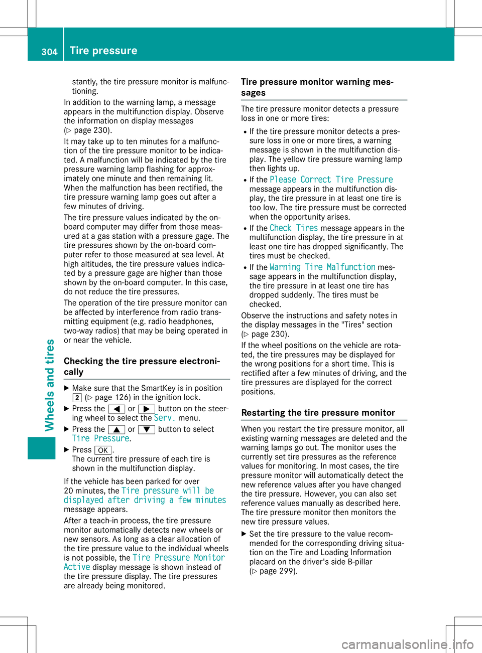
Checki ngthe tire pressure electroni-
cally X
Make surethattheSmartKey isin position
0048 (Ypage 126)inthe ignition lock.
X Press the0059 or0065 button onthe steer-
ing wheel toselect theServ. Serv.
menu.
X Press the0063 or0064 button toselect
Tire Pressure Tire
Pressure.
X Press 0076.
The current tirepressure ofeach tireis
shown inthe multifunction display.
If the vehicle hasbeen parked forover
20 minutes, theTire pressure willbe Tire
pressure willbe
displayed afterdriving afew minutes displayed
afterdriving afew minutes
message appears.
Aft erateach-in process, thetire pressure
monitor automatically detectsnewwheels or
new sensors. Aslong asaclear allocation of
the tire pressure valuetothe individua lwheels
is not possible ,the Tire Pressure Monitor Tire
Pressure Monitor
Active Active
displaymessage isshown instead of
the tire pressure display.The tirepressures
are alread ybeing monitored. Tire
pressure monitorwarning mes-
sages The
tirepressure monitordetectsapressure
loss inone ormore tires:
R Ifthe tire pressure monitordetectsapres-
sure lossinone ormore tires,awarning
message isshown inthe multifunction dis-
play .The yellow tire pressure warninglamp
then lights up.
R Ifthe Please Correct TirePressure Please
Correct TirePressure
message appearsinthe multifunction dis-
play ,the tire pressure inat least onetireis
too low. Thetirepressure mustbecorrect ed
when theopportunity arises.
R Ifthe Check Tires Check
Tiresmessage appearsinthe
multifunction display,the tire pressure inat
least onetirehas dropped significantly. The
tires must bechecked.
R Ifthe Warning TireMalfunction Warning
TireMalfunction mes-
sage appea rsinthe multifunction display,
the tire pressure inat least onetirehas
dropped suddenly .The tires must be
checked.
Observe theinstruct ionsandsafety notesin
the displa ymessages inthe "Tires" section
(Y page 230).
If the wheel positions onthe vehicle arerota-
ted, thetire pressures maybedispla yedfor
the wrong positions forashort time.Thisis
rectified afterafew minutes ofdriving, andthe
tire pressures aredispla yedforthe correct
positions.
Restart ingthe tire pressure monitor When
yourestart thetire pressure monitor,all
existing warning messages aredeleted andthe
warning lampsgoout. Themonitor usesthe
currently settire pressures asthe reference
values formonitoring. Inmost cases, thetire
pressure monitorwillautomaticall ydetect the
new reference valuesafteryouhave changed
the tire pressure. However, youcan also set
reference valuesmanuall yas described here.
The tirepressure monitorthenmonitors the
new tirepressure values.
X Set thetire pressure tothe value recom-
mended forthe corresponding drivingsitua-
tion onthe Tire andLoading Information
placard onthe driver's sideB-pillar
(Y page 299). 304
Tire
pressur eWheels andtires
Page 318 of 334

Treadw
earindic ators
Na rro wba rs (tre adwearbars) thatar edistri b-
ute dove rthe tire trea d.Ifthe tire trea dis level
wi th the bars, the wearlimit of00CD in(1.6 mm)
ha sbe en rea che d.
Oc cupant distrib utio n
The distri butio nof occu pants inaveh icleat
thei rde signa ted seating positio ns.
Total load limit
Nom inallo ad and lugga geload plus 68 kg
(150 lbs) mu ltiplied by the num berof sea tsin
the vehicle. Ch
ang ingawh eel Fl
at tire
The "Breakdo wnassista nce" section
(Y page 281 )conta insinfo rma tionand note s
on how todealwith afla ttire .Info rma tionon
dri ving with MOExte ndedtire sin the eventofa
fla ttire can befou ndund er"M OExtend edtire s
(ti res with run-fla tcha racteri stics"
(Y page 281) . Rotati
ngthe wheels G
WA
RNING
Ro tati ngthe fron tand rearwh eelsifthe
wh eelsor tire sha ve diffe rent dimens ions
ma ysev erelyimp airthe driving characteri s-
tics .The servicebra keorwh eelsu spe nsion
comp onents mayal so be dama ged. The reis
a ris kof an acci dent.
Ro tate front andrearwh eelsonl yif the
wh eelsand tiresar eof the same dimen-
si ons.
! On
veh icles equipp ed with atire pressu re
moni tor,electro niccomp onents arelocate d
in the wheel.
Ti re-m ounting toolssho uld not beused nea r
the valve .Thi scou ldda ma gethe electro nic
comp onents.
Onl yha ve tire scha nge dat aqu alifi ed spe -
cia list wo rksh op. Alw
ayspa yatte ntionto the instructio nsand
sa fety note swh en cha nging awh eel
(Y page 316 ).
The wearpatterns onthe fron tand reartire s
di ffe r,de pendi ng on the opera ting cond itions.
Ro tate thewheelsbe fore acle arwe arpattern
ha sform edon the tires.Front tirestyp ically
we armor eon the shoulde rand reartire sin
the cente r.
On veh icles tha tha ve the same size front and
rea rwh eels,yo ucan rotatethe wheelsacco rd-
ing tothe intervalsin the tire manuf actu rer's
wa rranty book inyour veh icledo cum ents. Ifno
wa rranty book isavaila bl e, the tiressho uld be
rota tedevery3,0 00 to6,0 00 miles(5,000 to
10, 000 km).Dep endingontire wear,thi sma y
be req uired earlier. Do not change thedirec-
tio nof wh eelrota tion.
Cl ea nthe conta ctsurfa ces ofthe wheeland
the brakedisc thor oughl yeve rytime awh eel
is rota ted.Ch eck thetire pressu reand reacti-
va te the tire pressu remoni torifnece ssary. Di
rec tionof rotati on
Ti res with aspe cified directi onofrota tionha ve
ad ditio nal benefi ts,e.g.if ther eis aris kof
hy dro plani ng. Theseadvantag escan onlybe
ga ine difthe tiresar eins talled corr espond ing
to the directi onofrota tion.
An arrow onthe side wa llof the tire indicates
its corr ectdirecti onofrota tion. Sto
ringwh eels
Store wheelstha tar enot being used inacoo l,
dry and preferablyda rk place .Pro tect thetires
from oil,gre ase, gasol ine and diese l. Mou
nting awh eel
Pre parin gthe vehic le X
Stop thevehicleon solid,non-sl ippe ry and
le vel ground .
X Unl oadthe vehicle. The jack canonlybe
us ed when the vehicleis unl aden.
X App lythe electri cpa rking brakema nua lly.
X Bri ng the fron twh eelsinto thestra ight-
ah eadpo sitio n. 31
6 Ch
ang ingawh eelWhe elsand tires
Page 320 of 334

R
The jack must beplaced onafirm, flatand
non- slipsurface. Onaloose surface, alarge,
flat, load-bearing underlaymustbeused. On
a slippery surface, anon- slipunderlay must
be used, e.g.rubber mats.
R Do not use wooden blocksorsimilar objects
as ajack underlay. Otherwise, thejack will
not beable toachieve itsload-bearing capa-
city due tothe restr icted height.
R Make surethatthedistance between the
underside ofthe tires andtheground does
not exceed 1.2in(3 cm).
R Never placeyourhands andfeet under the
raised vehicle.
R Do not lieunder thevehicle.
R Do not start theengine whenthevehicle is
raised.
R Do not open orclose adoor orthe trunk lid
when thevehicle israised.
R Make surethatnopersons arepresent in
the vehicle whenthevehicle israised.
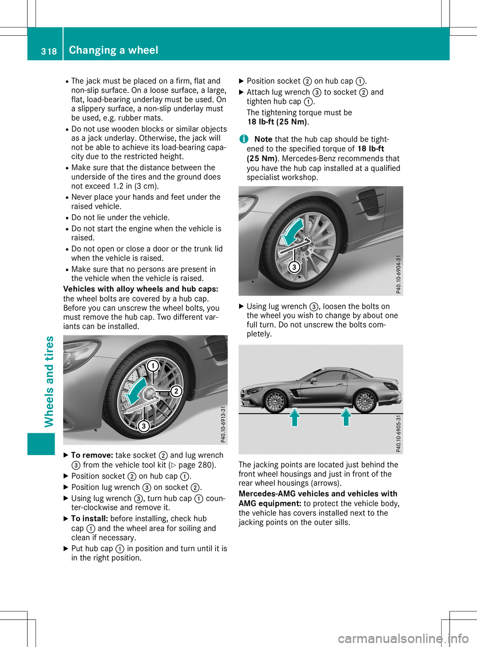
Vehicles withalloy wheels andhub caps:
the wheel boltsarecovered byahub cap.
Before youcan unscrew thewheel bolts,you
must remove thehub cap. Twodifferent var-
iants canbeinstalled. X
To remove: takesocket 0044and lugwrench
0087 from thevehicle toolkit(Ypage 280).
X Position socket0044onhub cap0043.
X Position lugwrench 0087onsocket 0044.
X Using lugwrench 0087,turn hubcap0043coun-
ter- clock wiseandremove it.
X To install: beforeinstalling, checkhub
cap 0043and thewheel areaforsoiling and
clean ifnecessary.
X Put hub cap0043inposition andturn until itis
in the right position. X
Position socket0044onhub cap0043.
X Attach lugwrench 0087tosocket 0044and
tighten hubcap0043.
The tighten ingtorque mustbe
18 lb-ft (25Nm).
i Note
thatthehub capshould betight-
ened tothe specified torqueof18 lb-ft
(25 Nm). Mercedes- Benzrecomm endsthat
you have thehub capinstalled ataqualified
specialist workshop. X
Using lugwrench 0087,loosen thebolts on
the wheel youwish tochange byabout one
full turn. Donot unscrew thebolts com-
pletely. The
jackingpoints arelocated justbehind the
front wheel housings andjust infront ofthe
rear wheel housings (arrows).
Mercedes-AMG vehiclesandvehicles with
AMG equipm ent:toprotec tthe vehicle body,
the vehicle hascovers installed nexttothe
jack ingpoints onthe outer sills. 318
Changing
awheelWheels andtires