2020 MERCEDES-BENZ GLE COUPE air vent
[x] Cancel search: air ventPage 36 of 757
Fo
rth is reason, thefo llowing can occur in isola‐
te d cases, depending on the aids used:
R Aids malfunctioning
R Adverse health ef fects
Obser vethe no tes and warnings of the manufac‐
turer of the aids; if in doubt, conta ctthe device
manufacturer and your doc tor.Mercedes-
Benz AGrecommends using only few electrical
ve hicle sy stems if there is continuing uncer tainty
concerning the possibility of aids malfunction‐
ing.
Ha ve repairs and maintenance workinthe area
of vehicle components car rying live voltage and
transmission aerials car ried out byaqu alified
specialist workshop. Implied
warra nty
* NO
TEDama getotheve hicle arising
from violation of these operating instruc‐
tions. Damage
totheve hicle can arise from viola‐
tion of these operating instructions. This damage is not co
vered either bythe
Mercedes-Benz implied warranty or bythe
New‑ or Used- Vehicle Warrant y. #
Follow the instructions in these operat‐
ing instructions on proper operation of
yo ur vehicle as well as on possible vehi‐
cle damage. QR code
forre scue card
The QR code is secured in the fuel filler flap and
on the opposite side on the B-pillar. In theeve nt
of an accident, rescue services can use the QR
code toquickly find the appropriate rescue card
fo ryo ur vehicle. The cur rent rescue card con‐
ta ins the most impor tant information about your
ve hicle in a compact form , e.g. thero uting of the
electric lines.
Fu rther information can be obtained at https://
www.mercedes-benz.de/qr-code. Data
storage Electronic control units
Elect
ronic control units are fitted in your vehicle.
Some of these are necessary forth e safe opera‐
tion of your vehicle, while some assist you when
driving (driver assis tance sy stems). In addition,
yo ur vehicle pr ovides com fort and enter tainment
functions, which are also made possible byelec‐
tronic control units.
Elect ronic control units contain da tamemories
which cantemp orarily or permanently store
te ch nical information about theve hicle's operat‐
ing state, component loads, main tenance
re qu irements and tech nical events or faults.
In general, this information documents thest ate
of a component part, a module, a sy stem or the
sur roundings such as:
R operating status of sy stem components (e.g.
fi ll le vels, battery status, tyre pressure)
R status messages concerning theve hicle or
its individual components (e.g. number of
wheel revo lutions/speed, longitudinal accel‐ General no
tes33
Page 37 of 757
eration, lateral acceleration, display of
fas‐
te ned seat belts)
R malfunctions or faults in impor tant sy stem
components (e.g. lights, brakes)
R information on events leading tovehicle
damage
R system reactions in special driving situations
(e.g. airbag deployment, inter vention of sta‐
bility control sy stems)
R ambient conditions (e.g. temp erature, rain
sensor)
In addition toprov iding the actual control unit
function, this data assists the manufacturer in
de tecting and rectifying faults and optimising
ve hicle functions. The majority of this data is
te mp orary and is only processed in theve hicle
itself. Only a small portion of the data is stored
in theev ent or fault memor y.
When your vehicle is serviced, tech nical da ta
from theve hicle can be read out byservice net‐
wo rkemplo yees (e.g. workshops, manufactur‐
ers) or third parties (e.g. breakdown services).
Services include repair services, maintenance
processes, warranty claims and quality assur‐ ance measures,
forex ample. The read out is per‐
fo rm ed via the legally prescribed port forthe
diagnostics connection in theve hicle. The
re spective service network locations or third
parties collect, process and use the data. They
document tech nical statuses of theve hicle,
assist in finding faults and impr oving quality and
are transmit tedto the manufacturer, if neces‐
sar y.Fu rthermore, the manufacturer is subject
to product liability. Forth is, the manufacturer
re qu ires tech nical da tafrom vehicles.
Fa ult memories in theve hicle can be reset by a
service outlet as part of repair or maintenance
wo rk.
Depending on the selected equipment, you can
import data into vehicle con venience and info‐
ta inment functions yourself.
This includes, forex ample:
R multimedia data such as music, films or pho‐
to sfo r playback in an integrated multimedia
sy stem
R address book data for use in connection with
an integrated hands-free sy stem or an inte‐
grated navigation sy stem R
entered navigation destinations
R data about the use of internet services
This data can be sa ved locally in theve hicle or it
is located on a device which you ha veconnected
to theve hicle (e.g. a smartphone, USB flash
drive or MP3 pla yer). If this data is stored in the
ve hicle, you can dele teit at any time. This data
is sent tothird parties only at your requ est, par‐
ticular lywhen you use online services in accord‐
ance with the settings that you ha veselected.
Yo u can store or change con venience settings/
individualisations in theve hicle at any time.
Depending on the equipment, this includes, for
ex ample:
R settings forth e seat and steering wheel posi‐
tions
R suspension and climate control settings
R customisations such as interior lighting
If yo ur vehicle is accordingly equipped, you can
connect your smartphone or ano ther mobile end
device totheve hicle. You can cont rolth is by
means of the control elements integrated in the
ve hicle. Images and audio from the smartphone 34
General no tes
Page 39 of 757
Re
stra int sy stem Pr
otection pr ovided bythere stra int sy stem The
restra int sy stem includes thefo llowing com‐
ponents:
R Seat belt sy stem
R Airbags
R Child restra int sy stem
R Child seat securing sy stems
The restra int sy stem can help pr eventtheve hi‐
cle occupants from coming into contact with
parts of theve hicle interior in theev ent of an
accident. In theev ent of an accident, the
re stra int sy stem can also reduce thefo rc es to
which theve hicle occupants are subjected.
A seat belt can only pr ovide the best le vel of pro‐
te ction if it is worncor rectl y.Depending on the
de tected accident situation, seat belt tensioners
and/or airbags supplement the pr otection
of fere dby a cor rectly wornseat belt. Seat belt
te nsioners and/or airbags are not depl oyed in
eve ryaccident. In order
forth ere stra int sy stem toprov ide the
intended le vel of pr otection, each vehicle occu‐
pant must obser vethefo llowing information:
R Fasten seat belts cor rectl y.
R Sit in an almost up right seat position with
th eir back against the seat backrest.
R Sit with their feet resting on thefloor, if pos‐
sible.
R Alw ays secure persons under 1.50 m tall in
an additional restra int sy stem suitable for
Mercedes-Benz vehicles.
Ho wever,no sy stem available today can com‐
ple tely elimin ate injuries and fata lities in every
accident situation. In particular, the seat belt
and airbag generally do not pr otect against
objects penetrating theve hicle from the outside.
It is also not possible tocompl etely rule out the
ri sk of injury caused bythe airbag deploying. Re
duced restra int sy stem pr otection &
WARNING Risk of inju ryor death from
modifications tothere stra int sy stem
The restra int sy stem can no longer function
cor rectly af ter alterations ha vebeen made.
The restra int sy stem may then not pr otect
th eve hicle occupants as intended byfailing
in an accident or triggering unexpec tedly, for
ex ample #
Never alter the parts of there stra int
sy stem. #
Neverta mp er with the wiring or any
electronic component parts or their
software. If it is necessary
tomodify theve hicle toaccom‐
modate a person with disabilities, con tact a
qu alified specialist workshop.
Mercedes-Benz recommends that you use driv‐
ing aids which ha vebeen appr ovedfo ryo ur vehi‐
cle byMercedes-Benz. 36
Occupant saf ety
Page 47 of 757
te
ctive function and deployment may even
cause fur ther injuries.
In order toavo idrisks, each vehicle occupant
must alw ays make sure of thefo llowing:
R Fasten seat belts cor rectly. Pregnant
wo men must take particular care to
ensure that the lap belt ne ver lies across
th e abdomen.
R Adopt the cor rect seat position and keep
as faraw ay as possible from the airbags.
R Obser vethefo llowing information. #
Alw ays make sure that there are no
objects between the airbag and vehicle
occupant. To
avo idtherisks resulting from the deployment
of an airbag, each vehicle occupant must
obser vethefo llowing information in particular:
R Before starting your journe y,adjust your seat
co rrectly; the driver's seat and front
passenger seat should be mo ved as far back
as possible. When doing so, alw
ays obser vethe informa‐
tion on the cor rect driver's seat position
(/ page 102).
R Onlyhold thesteering wheel bythesteering
wheel rim. This allow sth e airbag tobe fully
deplo yed.
R Alw ays lean against the seat backrest when
th eve hicle is in motion. Do not lean forw ards
or against the door or side windo w.You may
ot herwise be in the deployment area of the
airbags.
R Alw ayske ep your feet on thefloor. Do not
put your feet on the cockpit, forex ample.
Yo ur feet may otherwise be in the deploy‐
ment area of the airbag.
R Ifch ildren are tra velling in theve hicle,
obser vethe additional no tes (/ page 53).
R Alw aysstow and secure objects cor rectl y. Objects in
theve hicle interior may pr event an
airbag from functioning cor rectly. Each vehicle
occupant must alw ays make sure of thefo llow‐
ing in particular:
R There are no people, animals or objects
between theve hicle occupants and an air‐
bag.
R There are no objects between the seat, door
and door pillar (B-pillar).
R There are no hard objects, e.g. coat hangers,
hanging on the grab handles or coat hooks.
R There are no accessory parts, such as mobile
navigation devices, mobile phones or cup
holders, attached totheve hicle within the
deployment area of an airbag, e.g. on the
cockpit, on the door, on the side window or
on the side wall trim.
In addition, no connecting cables, tensioning
st ra ps or retaining stra ps must be routed or
attached totheve hicle within the deploy‐
ment area of an airbag. Alw ays comply with
th e accessory manufacturer's ins tallation
instructions and, in particular, the no tes on
suitable places for ins tallation. 44
Occupant saf ety
Page 133 of 757
At
taching a roof rack &
WARNING Risk of inju ryifth e maximum
ro of load is exceeded
When you load thero of, the cent reof gr avity
of theve hicle rises and the usual driving
ch aracteristics as well as thesteering and
braking characteristics change. During cor‐
nering, theve hicle tilts more strongly and
may react more sluggishly tosteering mo ve‐
ments.
If yo uexc eed the maximum roof load, the
driving characteristics, as well as thesteer‐
ing and braking characteristics, will be
great lyimpaired. #
Alw ays comply with the maximum roof
load and adjust your driving style. Yo
u will find information on the maximum roof
load in the "Technical data" section. *
NO
TEVehicle damage from non-
appr ovedro of racks The
vehicle could be damaged byroof racks
which ha venot been tested and appr ovedby
Mercedes-Benz. #
Use only roof rack ste sted and
appr ovedfo r Mercedes-Benz. #
Depending on theve hicle equipment,
ensure that when thero of rack isfitted,
th e sliding sunroof can be fully raised. #
Depending on theve hicle equipment,
ensure that when thero of rack isfitted,
th e boot lid can be fully opened. #
Position the load on thero of rack in
such a wayth at theve hicle will not sus‐
ta in damage even when it is in motion. *
NO
TEDama getothe panorama sliding
sunroof caused bya non-appr ovedro of
ra ck The panorama sliding sunroof may be dam‐
aged
bythero of rack ifyo u attem pttoopen it when using a
roof rack not tested and
appr ovedfo r Mercedes-Benz. #
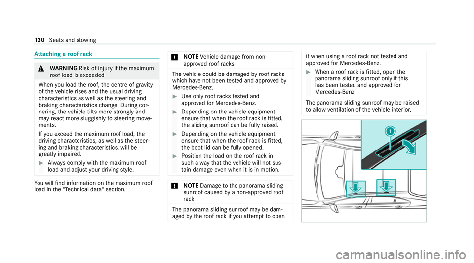
When a roof rack isfitted, open the
panorama sliding sunroof only if this
has been tested and appr oved for
Mercedes-Benz.
The panorama sliding sunroof may be raised
to allow ventilation of theve hicle interior. 13 0
Seats and stowing
Page 165 of 757
Au
tomatically controlling the climate control
in the rear In auto
matic mode, the set temp erature is regu‐
lated bythete mp erature of the dispensed air
and the air flow. #
Press the0058 button (/ page160). Overvi
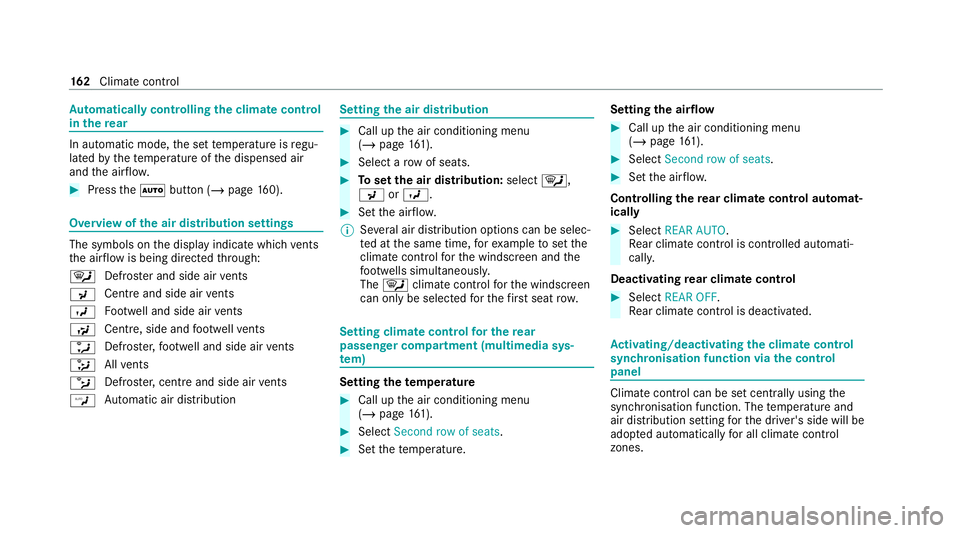
ewofthe air distribution settings The symbols on
the display indicate which vents
th e air flow is being directed thro ugh:
0061 Defros
ter and side air vents
009C Centre and side air
vents
009B Fo
otwe ll and side air vents
009F Centre, side and
foot we llve nts
0086 Defros
ter,fo ot we ll and side air vents
008F All
vents
0087 Defros
ter,centre and side air vents
00A2 Au
tomatic air distribution Setting
the air distribution #
Call up the air conditioning menu
(/ page 161). #
Select a rowof seats. #
Toset the air distribution: select0061,
009C or009B. #
Set the air flow.
% Several air distribution options can be selec‐
te d at the same time, forex ample toset the
climate control forth e windscreen and the
fo ot we lls simultaneousl y.
The 0061 climate contro lfo rth e windscreen
can only be selected forth efirs t seat row. Setting climate control
for the rear
passenger comp artment (multimedia sys‐
te m) Setting the
temperature #
Call up the air conditioning menu
(/ page 161). #
Select Second row of seats . #
Set thete mp erature. Setting
the airflow #
Call up the air conditioning menu
(/ page 161). #
Select Second row of seats . #
Set the air flow.
Controlling there ar climate control automat‐
ical ly #
Select REAR AUTO .
Re ar climate control is controlled automati‐
call y.
Deactivating rear climate control #
Select REAR OFF.
Re ar climate control is deactivated. Ac
tivating/deactivating the climate control
syn chro nisation function via the control
panel Climate control can be set centrally using
the
synchronisation function. The temp erature and
air distribution setting forth e driver's side will be
adop ted automatically for all clima tecontrol
zones. 16 2
Climate cont rol
Page 166 of 757
#
Press the 0 button.
The synchronisation function will be deactivated
if th e settings for one of theot her climate zones
are changed. Ac
tivating/deactivating the climate control
syn chro nisation function via the multimedia
sy stem Climate control can be set centrally using
the
synchronisation function. The driver's settings
fo rte mp erature, air flow and air distribution are
adop ted automatically for all clima tezones. #
Call up the air conditioning menu
(/ page 161). #
Select First row of seats . #
Select SYNC.
Depending on the pr evious status, the func‐
tion is activated or deactivated. Demisting
the windo ws Wi
ndo wsmis ted up on the inside #
Press the0058 button. #
Ifth e windo wscontinue tomist up: press the
0064 button.
Wi ndo wsmis ted up on the outside #
Switch on the windscreen wipers. #
Press the0058 button. Switching air-recirculation mode on/off
#
Press the0072 button.
The interior air will be recirculated.
Air-reci rculation mode automatically swit ches to
fresh air mode af ter some time.
% If air-recirculation mode is switched on, the
windo wsmay mist up more quickl y.Switch
on ai r-re circulation mode only brie fly. Switches
there sidual heat on/off Re
quirements: R
theve hicle is par ked.
It is possible tomake use of there sidual heat
from the engine tocontinue heating or ventilat‐
ing the front compartment of theve hicle for
appr oximately 30 minutes, depending on the
te mp erature set. #
Toactivate: press button 0056.
Re sidual heat will be switched off automaticall y. Switching
there sidual heat in there ar
on/off Re
quirements:
R The vehicle is par ked.
When there sidual heat of the engine is activated
in there ar compartment, you can heat or venti‐
la te there ar compartment for appro ximately
30 minutes. #
Press button 5(/ page 160). Clima
tecontrol 16 3
Page 168 of 757
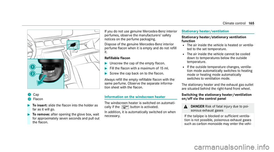
1
Cap
2 Flacon #
Toinser t:slide theflacon into the holder as
fa r as it will go. #
Toremo ve:af te r opening theglov e box, wait
fo r appro ximately se ven seconds and pull out
th eflacon. If
yo u do not use genuine Mercedes-Benz interior
pe rfumes, obse rveth e manufacturers' saf ety
notices on the perfume pac kaging.
Dispose of thege nuine Mercedes-Benz interior
pe rfume flacon when it is em pty and do not refill
it.
Re fillable flacon #
Unscr ew the cap of the em ptyflacon. #
Filltheflacon with a maximum of 15ml. #
Screw the cap back on totheflacon.
Alw aysre fill th e em ptyre fillable flacon with the
same perfume. Obser vethe separate informa‐
tion sheet with theflacon. Information on
the windscreen heater The windscreen heater is swit
ched on automati‐
cally if the 0064 button is activated.
In addition, it is automatically switched on when
necessar y. St
ationary heater/ventilation St
ationary heater/stationary ventilation
function R The air inside theve hicle is heated or ventila‐
te dto the set temp erature.
R The air inside theve hicle cannot be cooled
down totemp eratures below the outside
te mp erature.
R Ifth e outside temp erature changes, ventila‐
tion mode au tomatical lyswitches toheating
mode or heating mode automatically
switches toventilation mode.
The stationary heater and theex haust gas outlet
are situated behind theright-hand front wheel.
Switching thest ationary heater/ventilation
on/off via the control panel &
DANG ER Risk of fata l injury due topoi‐
sonous exhaust gases
If th eta ilpipe is bloc ked or suf ficient ventila‐
tion is not possible, poisonous exhaust gases
such as carbon monoxide may enter theve hi‐ Climate control
16 5