2020 MERCEDES-BENZ G-CLASS trailer
[x] Cancel search: trailerPage 211 of 530
R
Perm issible gross weight oftheto wing vehi‐
cle
R Perm issible gross weight ofthetra iler
R Maximum permissible speedofthetrailer
En sur eth efo llo wing beforest ar tin gajo ur ne y:
R The tirepr essur eon there ar axle oftheto w‐
ing vehicle issetfo ra maximu mloa d
R The lighting ofthecon nect edtrailer isoper a‐
tion al
In theev ent ofincr eased rear axle load, theve hi‐
cle/tr ailercombination mayno tex ceed amaxi ‐
mum speedof62 mph(1 00 km/h) forre ason s
con cerningth eoper ating permit. This also
applies incount ries inwhic hth eper missible
maximum speedforve hicle/tr ailercombinations
is abo ve62 mph(1 00 km/h) . At
tac hin gth eball neck &
WARNIN GRisk ofacci dent andinjury
due toan incorrectl yins talled ballcou‐
pling
If th eball coupling isno tins talled and
eng aged cor rectly ,it ma ybeco medetach ed
dur ing trav el and endang erother road user s.
Ther eis arisk offata linj ury. #
Installand secur eth eball coupling as
descr ibedintheball coupling manufac‐
tur er's installation instruct ions . #
When theball coupling hasbeen instal‐
led, ensureth at itis cor rectly secu red
bef oreev erytrip. &
WARNIN GRisk ofacci dent dueto an
inc orrectl yins talled and secur edball
couplin g
If th eball coupling hasnotbeen correctly
ins talled and secur ed,thetra iler can become
de tach ed. #
Installand secur eth eball coupling as
descr ibedintheball coupling manufac‐
tur er's installation instruct ions . #
When theball coupling hasbeen instal‐
led, ensureth at itis cor rectly secu red
bef oreev erytrip. Re
quirement s:
R The vehicle issecur edagains tro lling away.
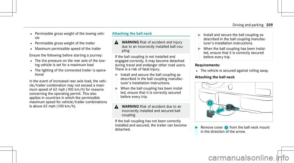
At tac hin gth eball neck #
Remo vecover1 from theball neckmount
in thedir ect ion ofthear row . Dr
iving and parking 209
Page 212 of 530
#
Storeco ver1 sothat itcan notmo ve
ar oun d. #
Obse rveth emanuf acturer'sinstallation
ins truct ions .
Obser vetheno teson loadi ngtheve hicle. Coupling
up/uncoupling atrailer Re
quirement s:
R The vehicle issecur edwithth eelectr icpar k‐
ing brak e.
R The transmission isin position 005D.
The trailer willbecor rectly detected bytheve hi‐
cle onlyif th efo llo wing condition sar eme t:
R The trailer isconn ectedcor rectl y.
R The trailer lighting system isin wo rking
or der .
The func tionsof thefo llo wing systems areaf fec‐
te dby acor rectly connect edtrai le r:
R ActiveLa ne Keeping Assist
R ESP®
trailer stabiliz ation R
Parking AssistPA RK TRONI C
R ActivePa rking Assist
R Blin dSpo tAss ist
R Drive Aw ayAssi st
R Cross Traf fic Aler t
R Rear vie wcam era
R 360° Camera
Ve hicl eswithout aleve lcontr olsystem: the
ball head height willchang edepen dingon the
ve hicle's load.Inthis case, useatrailer witha
height -adjustable draw bar .
Coupling upatrailer
* NO
TEDama getothebatt erydue tofull
disc harge Char
gingth etra iler batt eryusing thepo we r
supply ofthetra iler can damag eth eve hicle
batt ery. #
Donotus eth eve hicle's powe rsupp ly
to charge thetrailer battery. Inf
ormation abouta suit ablebal lnec kfo r
Mer cedes-Ben zve hicles canbeobt ained from a
qu alif ied spec ialistwo rkshop, e.g.anaut hor ized
Mer cedes-Benz Center. #
Remo vetheco verfr om theball neckmount
and stor eit in asaf eplace (/page209). #
Position thetra iler onaleve lsur face beh ind
th eve hicle andcouple itup totheve hicle. #
Establish theelectr icalconnect ionbetween
th eve hicle andthetra iler .
% Access oriescan beconnect edtotheper ma‐
nen tpo we rsupp lyup to180W and tothe
po we rsupp lythat isswit ched on via theigni‐
tion lock.
Decoup lingatrail er &
WARNIN GRisk ofbei ng crus hed and
beco ming trap ped whenunco upling a
tr ai le r
Whe nunco upling atrai le rwi th an eng aged
ine rtia-ac tivated brak e, your han dma y
bec ome trapped between theve hicle andthe
tr ai le rdr aw bar . 21
0
Driving and parking
Page 213 of 530

#
Donotunco upletrai le rs wit han
eng aged ove rrunbr ak e. *
NO
TEDama gewhen uncouplin gin a
st at eof ove rrun Unc
oupling inast at eof overru ncan dama ge
th eve hicle. #
Donotuncouple trailer swit han
eng aged ove rrunbr ak e. &
WARNIN GRisk ofbeco ming trap ped
whe ndisconnecti ngthetrailer cable
Ve hicl eswith leve lcontr olsystem: The
ve hicle maylo we rwhen thetra iler cable is
discon nected.
This could result inyouor other people
becoming trapped ifyo ur or their limbs are
be tween theve hicle body andthetir es or
under neathth eve hicle. #
Mak esur eth at nobody isunde rneat h
th eve hicle orintheimmediat evicinit y of
thewheel arch es when youdisc on‐
ne ct thetrailer cable. #
Disc onnect theelectr icalconnect ion
be tween theve hicle andthetra iler . #
Uncou ple th etra iler . #
Place theco veron theball neckmount . Ve
hicl eto wing instruct ions
The vehicle isno tsuit able forth euse oftow bar
sy stems that areused forflat towing ording hy
to wing, forex am ple. Attach ing and using tow bar
sy stems canlead todamag eon theve hicle.
When youar eto wing ave hicle withto w bar sys‐
te ms, safedr iving charact eristic scan notbe
guar anteed forth eto wing vehicle ortheto we d
ve hicle. Thevehicle-tr ailercombination may
sw erve from side toside. Complywithth eper‐
mitt edtowing methods (/page37 7) and the
ins truct ions forto wing withbo th axle son the
gr ou nd (/ page 378). Dr
iving andparking 21
1
Page 382 of 530
Esp
ecially so ifth eve hicle isladen.
R Neveratt em pttoreco vera ve hicle that is
st uc kwit hatrailer attached.
R Pull outtheve hicle that isstuc kbac kwards,
if poss ible, usingth etra cksit made beforeit
became stuc k. To
wing vehicl eaw ay intheeve ntofmalf unc‐
tions No
teson towing away intheev ent ofma l‐
fun ctions
* NO
TEDama gedue toinc orrect att ach‐
ment anduseof old nuts The
vehicle andcomponent sof theve hicle
can bedamag eddue toinc orrect att achment
and useof old nuts. #
Ifyo ure mo vethepr opeller shaft,place
th eM1 0nuts ontheM8 bolts as
spacer sand secur eth em withM8 nuts. #
Alw aysuse newself-loc kingnuts when
ins talling thepr opeller shafts. Obser
vetheno teson towing away
( / pag e37 7).
% Forfur ther information ,con sult anaut hor‐
ized Mercedes- BenzCenter.
To wing away intheev ent ofma lfun ctions
To wing away intheev ent ofdama getothe
engine, transm ission orelectr ics #
Shif tth etra nsmiss iontoposition 005C.
To wing away intheev ent oftransf ercase
da ma ge #
Remo vethepr opeller shaftsbetween the
axle sand thetransf ercase.
To wing away intheev ent offront axle dam‐
ag e #
Remo vethepr opeller shaftbe tween there ar
axle andthetransf ercase. #
Tow aw ay theve hicle withara ised front axle.
To wing away intheev ent ofrear axle dam‐
ag e #
Remo vethepr opeller shaftbe tween thefront
axle andthetransf ercase. #
Tow aw ay theve hicle withara ised rear axle
and withwheel roller sunder thefront axle. Loading
theve hicl efo rtr ans port #
Obser vetheno teson towing away
( / pag e37 7). #
Con nect theto w bar totheto wing eyein
or der toload theve hicle. #
Shif tth eaut omatic transmiss iontoposition
005C.
% The automatic transm ission maybe locked
in posit ion005Dintheeve ntofdama getothe
electr ics.Toshif tto 005C ,pr ov ide theon-
boar delectr icalsystem withpo we r
( / pag e37 5). #
Load theve hicle ontoth etra nspor ter. #
Shif tth eaut omatic transmiss iontoposition
005D. #
Use theelectr icpar king brak eto secur eth e
ve hicle agains tro lling away. #
Onlysecur eth eve hicle bythewheels. 380
Breakdo wnassis tance
Page 394 of 530
%
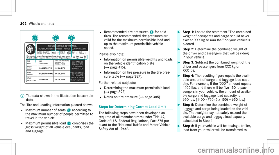
The datasho wnintheillus tration isexam ple
dat a.
The Tire and Loadi ngInfo rm atio nplacar dsho ws:
R Maximum numberofseats 2accor dingto
th emaximum numberofpeople permitt edto
tr ave lin theve hicle.
R Maximum permissible load3com prises the
gr os swe ight ofall vehicle occupants, load
and luggage. R
Recomme ndedtirepr ess ures 1 forcold
tir es. The recomme ndedtirepr ess ures are
va lid forth emaximum permissible loadand
up tothemaximum permissible vehicle
speed.
Please alsonote:
R Information onper missib lewe ight sand loads
on theve hicle identif ication plate
(/ page41 5).
R Info rm atio non tirepr essur ein thetir epr es‐
sur eta ble (/ page38 7).
Fu rther relat ed subje cts:
R Determ inin gth emaximum permissible load
(/ page392)
R Noteson tirepr essur e(/ page385). Ste
psforDe term ining Correct Load Limit The
follo wing steps have been developed as
re qu ired ofall manuf acturersunder Title 49,
Co de ofU.S. Feder alRe gulations, Part57 5pur‐
sua nttothe"N ational Traf fic and MotorVe hicle
Saf etyAc tof 1966". #
Ste p1: Loca tethest at emen t“T he combined
we ight ofocc upant sand cargoshould never
exc eed XXX kgorXXX lbs.”on your vehicle ’s
placar d. #
Ste p2: De term ine thecombin edweight of
th edr iver and passeng ersth at will beriding
in your vehicle. #
Ste p3: Sub tract thecombin edweight ofthe
dr iver and passeng ersfrom XXX kgor
XXX lbs. #
Ste p4: The resulting figur eeq uals theav ail‐
able amoun tof car goand luggageload capa‐
cit y.Fo rex am ple, ifth e“XXX” amount equals
14 00 lbs. and ther ewill befive 150lb pas ‐
seng ersin your vehicle, theamount ofavaila‐
ble cargoand luggageload capac ityis
65 0lbs. (140 0-75 0(5 x15 0) =650 lbs.) #
Ste p5: De term ine thecombin edweight of
lugg ageand cargobeing loaded ontheve hi‐
cle. That weight mayno tsaf elyexc eed the
av ailable cargoand luggageload capac ity
calc ulatedinStep 4. #
Ste p6: Ifyo ur vehicle willbetowing atrailer ,
load from your trailer willbetrans ferred to 392
Wheels andtires
Page 395 of 530
yo
ur vehicle. Consult this manual todeter‐
mine howthis reduces theav ailable cargo
and luggageload capac ityofyour vehicle.
% Notall vehicles areper mitt edtotow a
trailer .To wing atrailer isonl yper mittedifa
tra iler -hit chisins talled. Please consult an
aut hor ized Mercedes -Benz dealer ifyo uha ve
an yqu estion sabout towing atrailer with
yo ur vehicle.
Ev en ifyo uha ve cal cul ated thetot alload care‐
full y,yo usho uld still mak esur eth at themaxi‐
mum permissible gross mass andthemaximum
gr oss axle weight rating ofyour vehicle areno t
exc eeded. Details can befound ontheve hicle
identif ication plate. #
Have your loaded vehicle –including driver ,
occupants andload –we ighed onave hicle
we ighbr idge.
The measur edvalues mayno texc eed the
maximu mper missi blevalues stat ed on the
ve hicle identif ication plate.
Fu rther relat ed subje cts:
R Calculation exam ple forde term inin gth emax‐
imum load(/page393)
R Tire and Loadi ngInfo rm atio nplacar d
(/ page39 1)
R Tire pressur eta ble (/ page38 7)
R Vehicle identif ication plate Calculation
exam ple forde term ining the
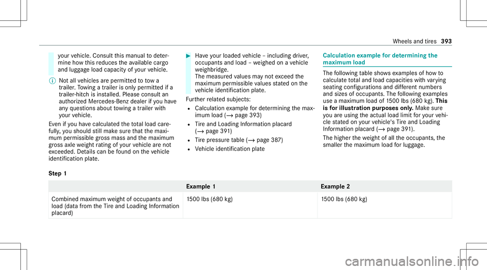
ma ximum load The
follo wing table showsexam ples ofhowto
cal cul ateto ta land load capac itieswithva rying
seatin gcon figur ations anddiffere nt num bers
and sizes ofocc upant s.The follo wing exam ples
use amax imum loadof1500 lbs (680 kg).This
is forillus tratio npur pos esonly.Mak esur e
yo uar eusin gth eactual loadlimit foryo ur vehi‐
cle stat ed on your vehicle's Tire and Loadi ng
In fo rm atio nplacar d(/ page39 1).
The high erthewe ight ofall theoccupant s,the
smaller themaximum loadforlug gage .
Ste p1 Ex
am ple 1E xamp le2
Combine dmaxim umweight ofocc upant sand
load (datafrom theTire and Loadi ngInfo rm atio n
placar d) 15
00 lbs (680 kg)1 500lbs(680 kg) Wheels
andtires 393
Page 403 of 530

Un
ifor m Tire Quality Grading Standar ds:a
unif orm standar dto grade thequ alit yof tires
wit hre ga rd totrea dqu alit y,tiretracti onand
te mp eratur ech aract eristic s.The qualit ygr adin g
asses smentismade bythemanuf acturerfollo w‐
ing spec ificat ions from theU. S. government. The
qu alit ygr ade ofatir eis im print ed on theside
wa llof thetir e.
Re comm endedtir epr essu re:th ere comme n‐
ded tirepr ess ureis thetir epr essur especif ied
fo rth etir es mount edtotheve hicle atthefa c‐
to ry.
The tireand information table con tains there c‐
omme ndedtirepr ess ures forcold tires, themax‐
imum permissible loadandthemaximum per‐
missible vehicle speed.
The tirepr essur eta ble con tains there comme n‐
ded tirepr ess ures forcold tires under various
oper ating condit ions,i.e.loading and/orspeed
of theve hicle.
Incr eased vehicl ewe ight duetooptiona l
eq uip ment :th ecombin edweight ofall standar d
and optio nal equipme ntavailable forth eve hicle, re
ga rdless ofwhe ther itis actually installed on
th eve hicle ornot.
Rim: thepar tof thewheel onwhic hth etir eis
ins talled.
GA WR (Gross AxleWe ight Ratin g):th eGA WR
is themaximum permissible axleload. The
actual loadonanaxle mustne verexc eed the
gr os saxle weight rating .The gross axlewe ight
ra ting canbefound ontheve hicle identif ication
plat eon theB‑pillar onthedr iver's side.
Speed ratin g:thespeed rating ispa rtof thetir e
identif ication .It specif iesthespeed rang efo r
whic hatir eis appr oved.
GV W(Gr oss Vehicl eWe ight ):th egr oss vehicle
we ight comprises thewe ight oftheve hicle
including fuel,tools, thespar ewheel, accesso‐
ri es installed, occupant s,lugg ageand thetrailer
dr aw bar nose weight ,if applicable. Thegros s
ve hicle weight mustno texc eed thegr oss vehicle
we ight rating GVWR asspecif iedontheve hicle
identif ication plateon theB‑pillar onthedr iver's
side.
GV WR (Gross Vehicl eWe ight Ratin g):th e
GV WR isthemaximum permitt edgross weight of
thefully laden vehicle (weight oftheve hicle
including allaccessor ies,occupants, fuel,lug‐
ga ge and thetrailer draw bar nose weight ifappli‐
cable). Thegros sve hicle weight rating issp eci ‐
fi ed on theve hicle identif ication plateon the
B‑pil laron thedr iver's side.
Maxim umweight ofthelad envehicl e:the
maximu mwe ight isthesum ofthecurb weight
of theve hicle, thewe ight oftheaccesso ries, the
maximu mloa dand thewe ight ofoption aleq uip‐
men tins talled atthefa ct or y.
Kilop ascal(kP a):metric unit fortir epr essu re.
6.9 kPacor responds to1psi .Ano ther unit for
tir epr es su re isbar .10 0kilop ascal(kP a)equals
1 bar .
Lo ad inde x:inadd ition totheload-bear ing
inde x,theload indexma yalso beimprint ed on
th eside wallof thetir e. This specif iestheload-
bear ingcapacity ofthetir emor epr ecisel y.
Cur bwe ight :th ewe ight ofave hicle withstand‐
ar deq uipme ntinc ludin gth emaximum capacity
of fuel, oiland coolant .It also includes theair
con ditionin gsy stem and option aleq uipment if Wheels
andtires 40
1
Page 427 of 530
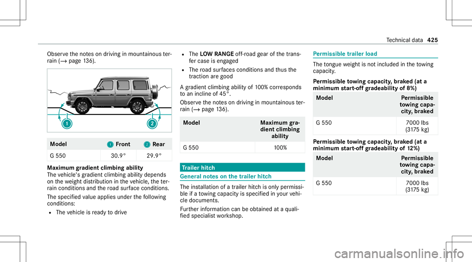
Obser
vetheno teson driving inmount ainous ter‐
ra in (/ page13 6). Mo
del
1 1
Front 2 2
Rear
G 550 30.9°29.9° Maximum
gradien tcli mbing ability
The vehicle's gradient climbing abilitydepends
on thewe ight distribution intheve hicle, thete r‐
ra in con dition sand thero ad sur face condi tions.
The specified va lue applies underthefo llo wing
con dition s:
R The vehicle isready todrive R
The LOWRAN GEoff-r oad gear ofthetra ns‐
fe rcase iseng aged
R The road sur faces condi tions andthus the
tr acti onarego od
A grad ient climbi ngability of100% corresponds
to an incline of45 °.
Obse rveth eno teson driving inmount ainous ter‐
ra in (/ page13 6). Model
Maximumgra‐
dien tcli mbing
abil ity
G 550 100% Tr
aile rhitc h Gene
ralno teson thetrailer hitch The
installation ofatrailer hitchis onl yper missi‐
ble ifato wing capac ityisspec ified inyour vehi‐
cle documents.
Fu rther information canbeobt ained ataqu ali‐
fi ed specialis two rkshop. Pe
rm issible trailer load The
tongu ewe ight isno tinc luded intheto wing
capac ity.
Pe rm issible towing capacit y,brak ed (at a
minim umstar t-of fgr adeabi lityof8%) Model
Perm issible
to wing capa‐
cit y,brak ed
G 550 7000lbs
(3 17 5kg ) Pe
rm issible towing capacit y,brak ed (at a
minim umstar t-of fgr adeabi lityof12%) Model
Perm issible
to wing capa‐
cit y,brak ed
G 550 7000lbs
(3 17 5kg ) Te
ch nica lda ta 425