2020 MERCEDES-BENZ CLS COUPE seats
[x] Cancel search: seatsPage 121 of 469
not be able
tobe charge d or connec ted with
th eve hicle's exterior aerial.
R The mobile phone may heat up during the
ch arging process. This may particular ly
depend on the applications (apps) cur rently
open in the bac kground.
R Toensure more ef ficient charging and con‐
nection with theve hicle's exterior aerial,
re mo vethe pr otective co ver from the mobile
phone. Pr otective co vers which are neces‐
sary for wireless charging are excluded.
R When charging, the mat should be used if
possible. Wire
lessly charging a mobile phone Requ
irements:
R The mobile phone is suitable for wireless
ch arging (Qi-compatible mobile phone).
A list of Qi-compatible mobile phones can be
fo und at: https://www.mercedes-benz-
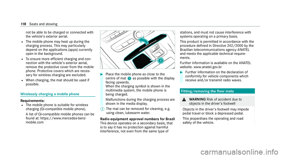
mobile.com #
Place the mobile phone as close tothe
centre of mat 1as possible wi th the display
fa cing up wards.
When thech arging symbol is shown in the
multimedia sy stem, the mobile phone is
being charge d.
Malfunctions during thech arging process are
shown in the media displa y.
% The mat can be remo vedfo r cleaning, e.g.
using clean, luk ewarmwate r.
Ra dio equipment appr oval numbers for Brazil
This device operates on a secondary basis, that
is to say it has no pr otection against harmful
inter fere nce, not even from the same type of st
ations, and must not cause inter fere nce wi th
sy stems operating on a primary basis.
This product is permitted in accordance with the
procedure defined in Directive 242/2000 bythe
Brazilian telecommunications agency AN ATEL
and meets the applicable tech nical requ ire‐
ments.
Fu rther information is available on the AN ATEL
we bsite. www.anatel.go v.br #
Further information on the declaration of
confo rmity forve hicle components which
re cei veand/or transmit radio wav es. Fi
tting/ removing the floormats &
WARNING Risk of accident due to
objects in the driver's foot we ll
Objects in the driver's foot we ll may impede
pedal tr avel or block a depressed pedal.
This jeopardises the operating and road
saf ety of theve hicle. 11 8
Seats and stowing
Page 122 of 469
#
Stow all objects in theve hicle securely
so that they cannot getinto the driver's
fo ot we ll. #
Alw aysfit th efloor mats securely and
as prescribed in order toensure that
th ere is alw ays suf ficient room forthe
pedals. #
Do not use loose floor mats and do not
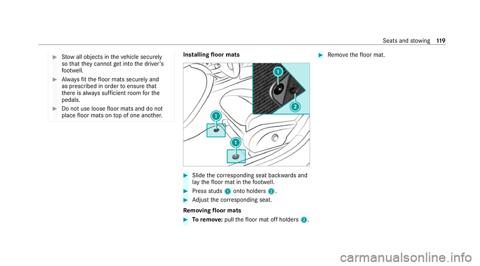
place floor mats on top of one ano ther. Installing floor mats
#
Slide the cor responding seat backwards and
lay thefloor mat in thefo ot we ll. #
Press studs 1onto holders 2. #
Adjust the cor responding seat.
Re moving floormats #
Toremo ve: pull thefloor mat off holders 2. #
Remo vethefloor mat. Seats and
stowing 11 9
Page 141 of 469
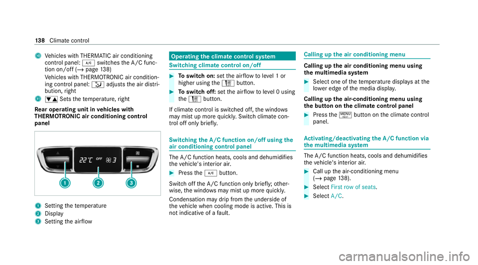
A
Vehicles with THERMATIC air conditioning
contro l panel: ¿switches the A/C func‐
tion on/off (/ page138)
Ve hicles with THERMOTRONIC air condition‐
ing contro l panel:_adjusts the air distri‐
bution, right
B w Setsthete mp erature, right
Re ar operating unit in vehicles with
THERMOTRONIC air conditioning control
panel 1
Setting thete mp erature
2 Display
3 Setting the air flow Operating
the clima tecont rol sy stem Switching clima
tecont rol on/off #
Toswitch on: setthe air flow toleve l 1 or
higher using theH button. #
Toswitch off: setthe air flow toleve l 0 using
th eH button.
If climate control is switched off, the windo ws
may mist up more quickl y.Switch climate con‐
trol off only brie fly. Switching
the A/C function on/off using the
air conditioning control panel The A/C function heats, cools and dehumidi
fies
th eve hicle's interior air. #
Press the¿ button.
Switch off the A/C function only brief ly;ot her‐
wise, the windo wsmay mist up more quickl y.
Condensation may drip from the underside of
th eve hicle when cooling mode is active. This is
not indicative of a fault. Calling up
the air conditioning menu Calling up
the air conditioning menu using
th e multimedia sy stem #
Select one of thete mp erature displa ysatthe
lo we r edge of the media displa y.
Calling up the air-conditioning menu using
th e but ton on the clima tecont rol panel #
Press the! button on the climate control
panel. Ac
tivating/deactivating the A/C function via
the multimedia sy stem The A/C function heats, cools and dehumidifies
th eve hicle's interior air. #
Call up the air-conditioning menu
(/ page 138). #
Select First row of seats. #
Select A/C. 13 8
Climate cont rol
Page 142 of 469
Setting climate control
toautomatic mode In auto
matic mode, the set temp erature is con‐
trolled and maintained at a const ant levelby the
air suppl y. #
Press the à button. #
Toswitch tomanual mode: pressthe H
or _ button. Climate
style Climate
style function
The following climate styles are available in auto‐
matic mode:
R FOCUS: high air flow , slightly cooler setting
R MEDIUM: medium air flow ,st andard setting
R DIFFUSE: low airflow , slightly warmer and
draught-f ree setting
Setting the clima testyle #
Call up the air conditioning menu
(/ page 138). #
Select First row of seats orSecond row of
seats. #
Call up theCLIMATE MODE menu. #
Select a climate style. Setting
the air distribution #
Call up the air conditioning menu
(/ page 138). #
Select a rowof seats. #
Toset the air distribution: select¯,
P orO. #
Set the air flow.
% Several air distribution options can be selec‐
te d at the same time, forex ample toset the
climate control forth e windscreen and the
fo ot we lls simultaneousl y.
The ¯ climate contro lfo rth e windscreen
can only be selected forth efirs t seat row. Ac
tivating/deactivating the climate control
syn chro nisation function via the air condi‐
tioning control panel Climate control can be set centrally using
the
synchronisation function. The temp erature and air distribution settings
forth e driver's side will
be adop ted automatically forth e front passenger
side. #
Press the0 button.
The synchronisation function will be deactivated
if th e settings for one of theot her climate con‐
trol zones are changed. Ac
tivating/deactivating the climate control
syn chro nisation function via the multimedia
sy stem Climate control can be set centrally using
the
synchronisation function. The driver's settings
fo rte mp erature, air quantity and air distribution
are adop ted automatically for all clima tezones. #
Call up the air conditioning menu
(/ page 138). #
Select First row of seats. #
Select SYNC. Clima
tecontrol 13 9
Page 244 of 469

R
Alw ays distribute the load on the bicycle rack
as eve nly as possible across theve hicle's
longitudinal axis.
Mercedes-Benz recommends removing all
de tach able parts from bicycles (e.g. bask ets,
ch ild seats, rech arge able bat teries) before load‐
ing them onto the bicycle rack . This will impr ove
th e aerodynamic resis tance and centre of gr avity
of the bicycle rack.
Alw ays secure the bicycles topreve ntthem from
moving around and check them at regular inter‐
va ls to ensure that they are secure.
Do not use tarp aulins or other co vers. The driv‐
ing characteristics and rear view may be
impaired. In addition, aerodynamic resis tance
and the load on the trailer hitch will increase. Load distribution on
the bicycle rack
1 Vertical dis tance between centre of gr avity
and ball head
2 Horizon tal dis tance between centre of gr av‐
ity and ball head
3 The centre of gr avity is on theve hicle's
centre axis
Obse rveth efo llowing information when loading
th e bicycle rack: Loading
the bicycle rack 3 bicycles 4 bicycles
To talwe ight of
bicycle rack
and load Up
to75 kg Up to
10 0kg
Max. dis tance
1 420 mm 420 mm
Max. di stance
2 300 mm 400 mm When transpo
rting four bic ycles or with a total
we ight between 75kgand 100kg , alw ays use
bicycle rack s with additional support on the
trailer hitch guide pin. Ve
hicle towing instructions
The vehicle is not suitable forth e use of tow bar
sy stems that are used forflat towing or ding hy
to wing, forex ample. Attach ing and using tow bar
sy stems can lead todamage on theve hicle.
When you are towing a vehicle with tow bar sys‐
te ms, safe driving characteristics cannot be Driving and parking
241
Page 259 of 469
Switching
there ading light and sear chlight
and on or off Re
quirements:
R For the reading light: the function is availa‐
ble when it is dar k.
R The hand mo vement take s place in the inter‐
action area below the inside rearview mir ror.
R For the sear chlight: the function is availa‐
ble when it is dar k.
R The hand mo vement take s place in the inter‐
action area abo vethe front passenger seat.
R The seat belt on the front passenger seat
must notbe inser ted in the seat belt buckle. Switching
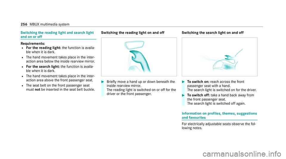
there ading light on and off #
Brief lymo vea hand up or down beneath the
inside rearview mir ror.
The reading light is swit ched on or off forthe
driver or the front passenger. Switching
the sear chlight on and off #
Toswitch on: reach across the front
passenger seat with a hand.
The sear chlight is switched on forth e driver. #
Toswitch off: take a hand back away from
th e front passenger seat.
The sear chlight is switched off again. Information on profiles,
themes, suggestions
and favo urites Fo
r electrical lyadjus table seats obser vethefo l‐
lowing no tes. 256
MBUX multimedia sy stem
Page 333 of 469
The load conditions "partially laden" and "fully
laden" are defined in
theta ble for dif fere nt num‐
be rs of passengers and amounts of luggage. The
actual number of seats may dif fer from this. Ty
re pressure moni toring sy stem Fu
nction of the ty repressure moni toring sys‐
tem
The sy stem checks the tyre pressure and the
tyre temp erature of the tyres fitted totheve hicle
by means of a tyre pressu resensor.
The tyre pressure and the tyre temp erature
appear in the on-board computer (/ page 330).
If th ere is a subs tantial pressure loss or if the
tyre temp erature is excessive, you will be
wa rned in thefo llowing ways:
R via display messa ges (/ page 404).
R viatheh warning lamp in the instrument
clus ter (/ page 427)
The tyre pressu remonitoring sy stem is only an
aid. It is the driver's responsibility toset the tyre pressure
tothere commended cold tyre pressure
suitable forth e operating situation.
In most cases, the tyre pressure monitoring sys‐
te m will auto maticallyupdate the new refere nce
va lues af teryo u ha vechanged the tyre pressure.
Yo u can, ho wever,also update there fere nce val‐
ues byrestarting the tyre pressure monitoring
sy stem manually (/ page 427).
Sy stem limits
The sy stem may be impaired or may not function
particular lyin thefo llowing situations:
R the tyre pressure has been set incor rectly
R sudden pressure loss caused byafo re ign
object penetrating the tyre, forex ample
R there is a malfunction caused byano ther
ra dio signal source
Checking the ty repressure with the tyre
pressure moni toring sy stem
Re quirements:
R The ignition is switched on. On-board computer:
4 Service 5
Tyres
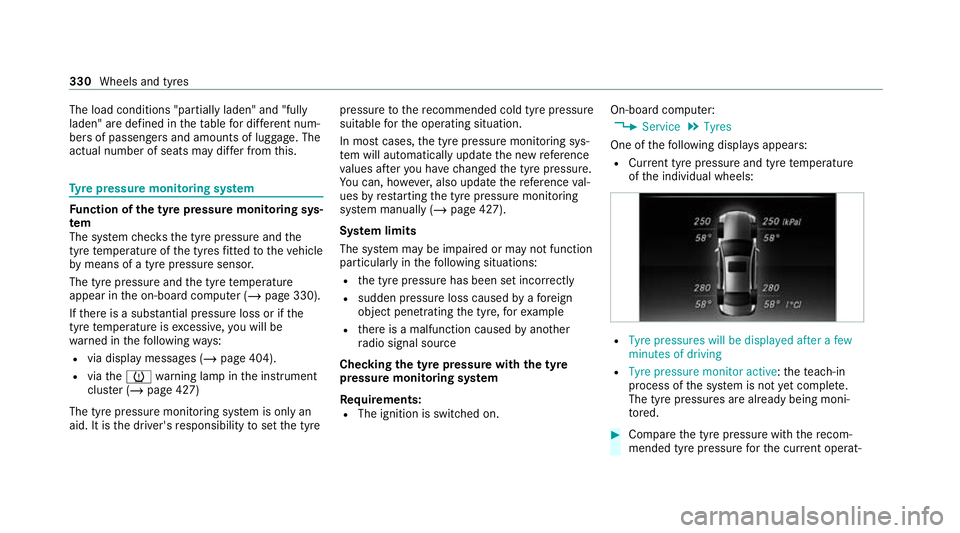
One of thefo llowing displa ysappears:
R Cur rent tyre pressure and tyre temp erature
of the individual wheels: R
Tyre pressures will be displayed after a few
minutes of driving
R Tyre pressure monitor active: thete ach-in
process of the sy stem is not yet compl ete.
The tyre pressures are already being moni‐
to re d. #
Compare the tyre pressure with there com‐
mended tyre pressure forth e cur rent operat‐ 330
Wheels and tyres
Page 437 of 469
Pa
int wo rk ............................................ 301
Plastic trim .......................................... 304
Re alwo od/trim elements ...................3 04
Re versing camera ................................ 302
Ro of lining ...........................................3 04
Seat belt .............................................. 304
Seat co ver ........................................... 304
Sensors ............................................... 302
St eering wheel .................................... 304
Ta ilpipes .............................................. 302
Tr ailer hit ch......................................... 302
Wa shing byhand ................................. 301
Wheels/rims ....................................... 302
Wi ndo ws .............................................. 302
Wi per blades .......................................3 02
Carpet (Care) .......................................... .304
Changing gears ........................................ 16 4
Manually ..............................................1 64
Changing hub caps .................................. 337
Changing the lights
Driving abroad (symm etrical low
beam) .................................................. 12 0
Cha rging
Bat tery (vehicle) ...................................3 18USB port ..............................................1
16
Chassis Damping characteristics ...................... 214
DY NA MIC BODY CONTROL .................. 214
Chassis le vel (AIR BODY CONT ROL)
Setting ................................................ .215
Child saf ety lock
Re ar door .............................................. 68
Re ar side wind ows................................. 70
Child seat Appr oval categories .............................. .56
At tach ing (no tes) ................................... 55
Basic instructions ..................................51
Fr ont passenger seat (no tes) ................. 66
Fr ont passenger seat (without auto‐
matic airbag shutoff) ............................. 66
ISOFIX/i-Size (fitting) ............................59
No tes on risks and dangers ...................52
Re commended child restra int sys‐
te ms ...................................................... 54
Seats suitable for belt-secu redch ild
re stra int sy stems ................................... 63
Seats suitable for i‑Size child
re stra int sy stems ................................... 59 Seats suitable
for ISOFIX child
re stra int sy stems ................................... 58
Securing on the co-driver seat ............... 67
Secu ring on there ar seat ...................... 64
To pTe ther ..............................................61
Child ren
Av oiding dangers in theve hicle .............52
Basic instructions .................................. 51
Chock ...................................................... .336
St orage location ..................................3 36
Cho ck
see Chock
City lighting ..............................................1 25
Cleaning see Care
Climate control ........................................ 137
Ac tivating/deactivating the A/C
function (cont rol panel) ...................... .138
Ac tivating/deactivating the A/C
function (MBUX multimedia sy stem) ... 13 8
Ac tivating/deactivating the synchro‐
nisation function (cont rol panel) .......... 13 9434
Index