2020 MERCEDES-BENZ C-CLASS ESTATE wheel
[x] Cancel search: wheelPage 228 of 565
lane, especially if
Active Lane Keeping
Assist alerts you. Be sure
toobser vethe sy stem limitations of
Ac tive Lane Keeping Assist. #
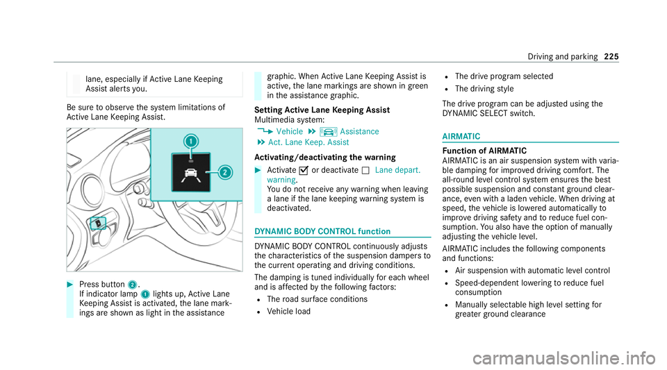
Press button 2.
If indicator lamp 1lights up, Active Lane
Ke eping Assist is activated, the lane mark‐
ings are shown as light in the assis tance graphic. When
Active Lane Keeping Assist is
active, the lane markings are shown in green
in the assis tance graphic.
Setting Active Lane Keeping Assist
Multimedia sy stem:
4 Vehicle 5
k Assistance
5 Act. Lane Keep. Assist
Ac tivating/deactivating the warning #
Activate Oor deacti vate ª Lane depart.
warning.
Yo u do not recei veany warning when leaving
a lane if the lane keeping warning sy stem is
deactivated. DY
NA MIC BODY CONT ROL function DY
NA MIC BODY CONTROL continuously adjusts
th ech aracteristics of the suspension dampers to
th e cur rent operating and driving conditions.
The da mping is tuned individually for each wheel
and is af fected bythefo llowing factors:
R The road sur face conditions
R Vehicle load R
The drive program selected
R The driving style
The drive program can be adjus ted using the
DY NA MIC SELECT switch. AIRMATIC
Fu
nction of AIRMATIC
AIRMATIC is an air suspension sy stem with varia‐
ble damping for impr oved driving comfort. The
all-round le vel control sy stem ensures the best
possible suspension and const antground clear‐
ance, even with a laden vehicle. When driving at
speed, theve hicle is lo wered automatically to
impr ovedriving saf ety and toreduce fuel con‐
sum ption. You also ha vethe option of manually
adjusting theve hicle le vel.
AIRMATIC includes thefo llowing components
and functions:
R Air suspension with automatic le vel control
R Speed-dependent lo wering toreduce fuel
consum ption
R Manually selec table high le vel setting for
grea ter ground clea rance Driving and pa
rking 225
Page 229 of 565
R
ADS PLUS (Ada ptive Damping Sy stem with
const ant damping forc e adjustment)
R DYNA MIC SELECT switch and le vel button
Av ailable suspension settings
A (Comfort)
R The suspension setting is comfor table.
R The vehicle is set tothe normal le vel.
R When driving at speeds abo ve125 km/h the
ve hicle is lo wered.
R When driving at speeds below 80 km/ h,the
ve hicle is raised again.
; (Econo my)
R The suspension setting is comfor table.
R The vehicle is set tothe low le vel.
R The vehicle is not lo wered any fur ther if you
are tra velling at higher speeds.
C (Sport)
R The suspension setting is firm er.
R The vehicle is set tothe low le vel. R
The vehicle is not lo wered any fur ther if you
are tra velling at higher speeds.
B (Sport Plus)
R The suspension setting is evenfirm er.
R The vehicle is set tothe low le vel.
R The vehicle is not lo wered any fur ther if you
are tr avelling at higher speeds.
% Operation with a trailer or bicycle rack:if
transport equipment, such as a trailer or a
bicycle rack , is attached tothe trailer hitch
and the electrical connection has been cor‐
re ctly es tablished, theve hicle remains at
normal le vel ir respective of speed or the
drive prog ram selected.
Setting theve hicle le vel &
WARNING Risk of accident because
ve hicle le vel is too high
Driving characteristics may be impaired.
The vehicle can drift outwards, forex ample,
when steering or cornering. #
Choose a vehicle le vel which is suited
to the driving style and thero ad sur face
conditions. &
WARNING Risk of entrapment from vehi‐
cle lo wering
When lo wering theve hicle, other people
could become trapped if their limbs are
between theve hicle body and the tyres or
underneath theve hicle. #
Make sure no one is underneath the
ve hicle or in the immediate vicinity of
th e wheel ar ches when theve hicle is
being lo wered. &
WARNING Risk of becoming trapped
due totheve hicle lo wering
Ve hicles with AIRMATIC or le vel control:
when you unload luggage or lea vetheve hi‐
cle, theve hicle firs trises slightly and then
re turns tothe set le vel shortly af terw ards. 226
Driving and parking
Page 230 of 565
Yo
u or an yone else in the vicinity of the
wheel ar ches or the underbody could thus
become trapped.
The vehicle can also be lo wered af ter being
loc ked. #
When leaving theve hicle, make sure
th at nobody is in the vicinity of the
wheel ar ches or the underbody. *
NO
TEDama gedue tovehicle lo wering Pa
rts of the body could be damaged when
th eve hicle is lo wered. #
Make sure that there are no obs tacles
such as kerbs underneath or in the
immediate vicinity of the body when the
ve hicle is being lo wered. Re
quirements:
R The vehicle has been star ted.
R The vehicle must not be moving fasterthan
60 km/h. Ra
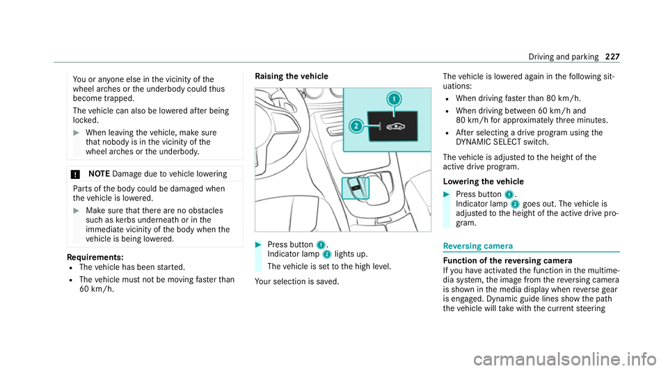
ising theve hicle #
Press button 1.
Indica tor lamp 2lights up.
The vehicle is set tothe high le vel.
Yo ur selection is sa ved. The
vehicle is lo wered again in thefo llowing sit‐
uations:
R When driving fasterthan 80 km/h.
R When driving between 60 km/h and
80 km/h for appro ximately thre e minutes.
R After selecting a drive program using the
DY NA MIC SELECT switch.
The vehicle is adjus tedto the height of the
active drive program.
Lo weri ngtheve hicle #
Press button 1.
Indica tor lamp 2goes out. The vehicle is
adjus tedto the height of the active drive pro‐
gram. Re
versing camera Fu
nction of there ve rsing camera
If yo u ha veactivated the function in the multime‐
dia sy stem, the image from there ve rsing camera
is shown in the media display when reve rsege ar
is engaged. Dynamic guide lines show the path
th eve hicle will take with the cur rent steering Driving and parking
227
Page 234 of 565
To
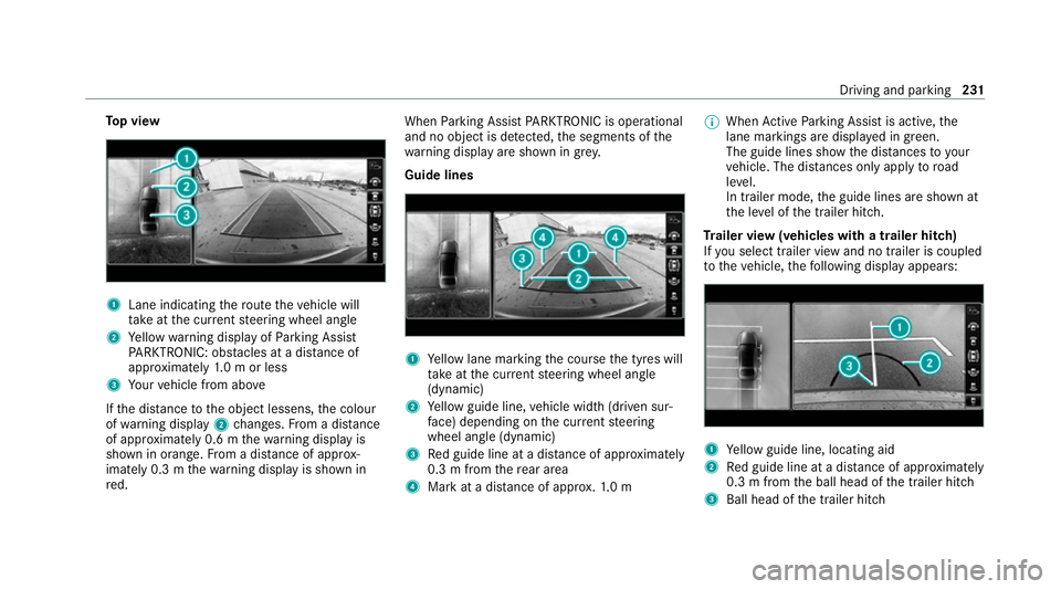
p view 1
Lane indicating thero ute theve hicle will
ta ke atthe cur rent steering wheel angle
2 Yellow warning display of Parking Assist
PA RKTRONIC: obstacles at a dis tance of
appr oximately 1.0 m or less
3 Your vehicle from abo ve
If th e dis tance tothe object lessens, the colour
of wa rning display 2changes. From a dis tance
of appr oximately 0.6 m thewa rning display is
shown in orange. From a dis tance of appr ox‐
imately 0.3 m thewa rning display is shown in
re d. When
Parking Assist PARKTRONIC is operational
and no object is de tected, the segments of the
wa rning display are shown in grey.
Guide lines 1
Yellow lane marking the course the tyres will
ta ke atthe cur rent steering wheel angle
(dynamic)
2 Yellow guide line, vehicle width (driven sur‐
fa ce) depending on the cur rent steering
wheel angle (dynamic)
3 Red guide line at a dis tance of appr oximately
0.3 m from there ar area
4 Mark at a distance of appr ox.1. 0 m %
When Active Parking Assist is active, the
lane markings are displa yed in green.
The guide lines show the dis tances to your
ve hicle. The dis tances only apply toroad
le ve l.
In trailer mode, the guide lines are shown at
th e le vel of the trailer hitch.
Tr ailer view (vehicles with a trailer hitch)
If yo u select trailer view and no trailer is coupled
to theve hicle, thefo llowing display appears: 1
Yellow guide line, locating aid
2 Red guide line at a dis tance of appr oximately
0.3 m from the ball head of the trailer hitch
3 Ball head of the trailer hitch Driving and parking
231
Page 235 of 565
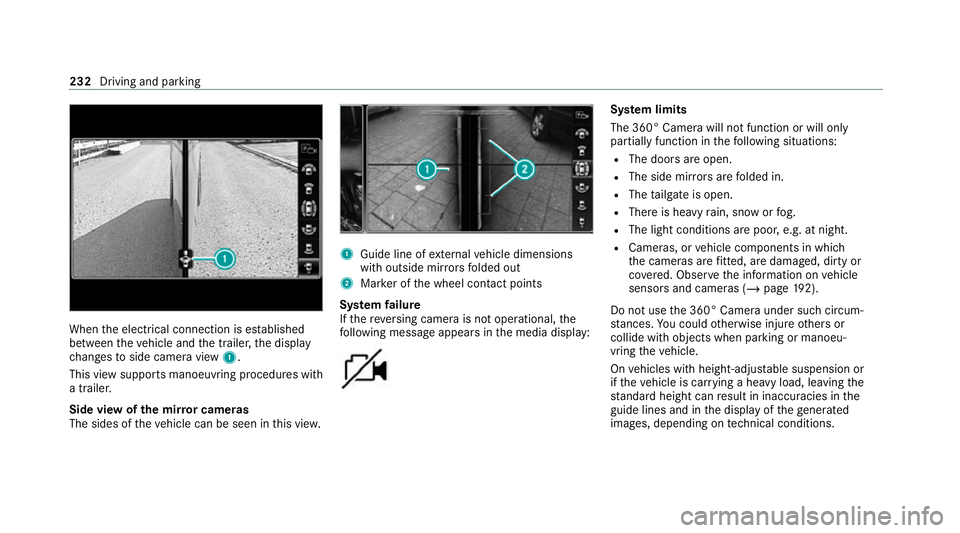
When
the electrical connection is es tablished
between theve hicle and the trailer, the display
ch anges toside camera view 1.
This view supports manoeuvring procedures with
a trailer.
Side view of the mir ror cameras
The sides of theve hicle can be seen in this vie w. 1
Guide line of extern al vehicle dimensions
with outside mir rors folded out
2 Marker of the wheel conta ct points
Sy stem failure
If th ere ve rsing camera is not operational, the
fo llowing message appears in the media display: Sy
stem limits
The 360° Camera will not function or will only
partially function in thefo llowing situations:
R The doors are open.
R The side mir rors are folded in.
R The tailgate is open.
R There is heavy rain, snow or fog.
R The light conditions are poor, e.g. at night.
R Cameras, or vehicle components in which
th e cameras are fitted, are dama ged, dirty or
co vered. Obser vethe information on vehicle
sensors and cameras (/ page192).
Do not use the 360° Camera under such circum‐
st ances. You could otherwise injure others or
collide with objects when parking or manoeu‐
vring theve hicle.
On vehicles with height-adjus table suspension or
if th eve hicle is car rying a heavy load, leaving the
st andard height can result in inaccuracies in the
guide lines and in the display of thege nerated
ima ges, depending on tech nical conditions. 232
Driving and pa rking
Page 243 of 565
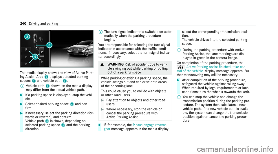
The media display sho
ws the view of Active Park‐
ing Assist. Area 2displa ysdetected park ing
spaces 4and vehicle path 3.
% Vehicle path 3shown on the media display
may dif fer from the actual vehicle path. #
If a parking space is displa yed: stop theve hi‐
cle. #
Select desired parking space 4and con‐
fi rm. #
If necessar y,select the parking direction (for‐
wa rds or reve rse), and confi rm.
Ve hicle path 3is shown, depending on
selected parking space 4and the parking
direction. %
The turn signal indicator is switched on auto‐
matically when the parking procedure
begins.
Yo u are responsible for selecting the turn signal
indicator in accordance with the traf fic condi‐
tions. If necessar y,select the turn signal indica‐
to r according ly. &
WARNING Risk of accident due tovehi‐
cle swinging out while parking or pulling
out of a parking space
While parking or exiting a parking space, the
ve hicle swings out and can drive onto areas
of the oncoming lane.
This could cause youto collide wi thobjects
or other road users. #
Pay attention toobjects and other road
users. #
Where necessar y,stop theve hicle or
cancel the parking procedure with
Ac tive Parking Assist. #
If,forex ample, thePlease engage reverse
gear message appears in the media display: select
the cor responding transmission posi‐
tion.
The vehicle drives into the selected parking
space.
% During the parking procedure with Active
Pa rking Assist, the lane markings are dis‐
pla yed in green in the camera image.
On completion of the parking procedure, the
Ø Active Parking Assist finished, take con-
trol of the vehicle. displaymessa geappears. Fur‐
th er manoeuvring may still be necessar y. #
After completion of the parking procedure,
safeguard theve hicle against rolling away.
When requ ired bylegal requirements or local
conditions: turn the wheels towa rdsth eke rb.
% You can stop theve hicle and change the
transmission position du ring the parking pro‐
cedure. The sy stem then calculates a new
ve hicle path. If no new vehicle path is availa‐
ble, the sy stem can change the transmission
position again or cancel the parking proce‐
dure. 240
Driving and pa rking
Page 250 of 565
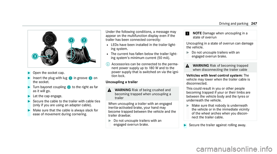
#
Open the soc ket cap. #
Inse rtthe plug with lug 1in groo ve3 on
th e soc ket. #
Turn bayonet coupling 2totheright as far
as it will go. #
Let the cap engage. #
Secure the cable tothe trailer with cable ties
(only if you are using an adap ter cable). #
Make sure that the cable is alw ays slack for
ease of mo vement during cornering. Under
thefo llowing conditions, a message may
appear on the multifunction display even if the
trailer has been connected cor rectly:
R LEDs ha vebeen ins talled in the trailer light‐
ing sy stem.
R The cur rent has fallen below the trailer light‐
ing sy stem's minimum cur rent (50 mA).
% Accessories can be connected tothe perma‐
nent po wer supp lyup to180 W and tothe
po we r supp lythat is swit ched on via the igni‐
tion loc k.
Un coupling a trailer &
WARNING Risk of being crushed and
becoming trapped when uncoupling a
trailer
When uncoupling a trailer with an engaged
ine rtia-activated brake, your hand may
become trapped between theve hicle and the
trailer dr awbar. #
Do not uncouple trailers with an
engaged overrun brake. *
NO
TEDama gewhen uncoupling in a
st ate of overrun Uncou
pling in a state of overru n can dama ge
th eve hicle. #
Do not uncouple trailers with an
engaged overrun brake. &
WARNING Risk of becoming trapped
when disconnecting the trailer cable
Ve hicles with le vel control sy stem: The
ve hicle may lo wer when the trailer cable is
disconnected.
This could result in you or other people
becoming trapped if your or their limbs are
between theve hicle body and the tyres or
underneath theve hicle. #
Make sure that nobody is unde rneath
th eve hicle or in the immediate vicinity
of the wheel ar ches when you discon‐
nect the trailer cable. #
Secure the trailer against rolling away. Driving and pa
rking 247
Page 255 of 565
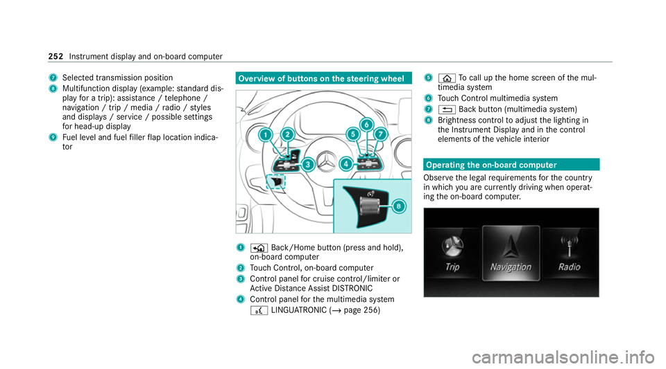
7
Selected transmission position
8 Multifunction displ ay(exa mp le:standard dis‐
play for a trip): assi stance / telephone /
navigation / trip / media / radio / styles
and displa ys/ service / possible settings
fo r head-up display
9 Fuel le vel and fuel filler flap location indica‐
tor Overview of buttons on
thest eering wheel 1
P Back/Home button (press and hold),
on-board computer
2 Touch Control, on-board co mputer
3 Control panel for cruise control/limiter or
Ac tive Dis tance Assi stDISTRONIC
4 Control panel forth e multimedia sy stem
£ LINGU ATRO NIC (/ page 256) 5
ò Tocall up the home screen of the mul‐
timedia sy stem
6 Touch Control multimedia sy stem
7 % Back button (multimedia sy stem)
8 Brightness control toadjust the lighting in
th e Instrument Display and in the control
elements of theve hicle interior Operating
the on-boa rdcompu ter
Obser vethe legal requ irements forth e count ry
in which you are cur rently driving when operat‐
ing the on-board computer. 252
Instrument display and on-board computer