2020 MERCEDES-BENZ C-CLASS ESTATE height
[x] Cancel search: heightPage 181 of 565
#
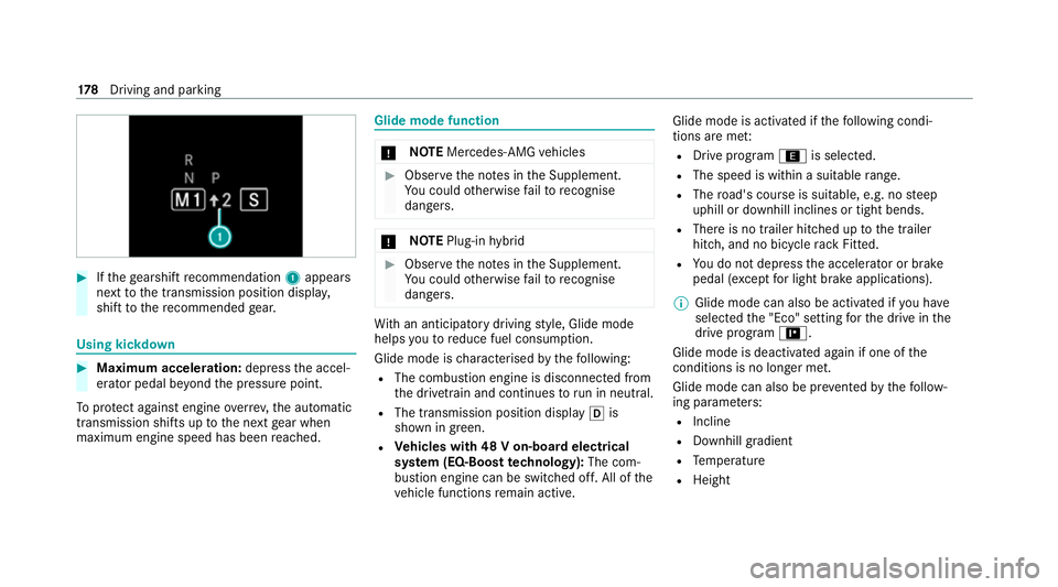
Ifth ege arshift recommendation 1appea rs
next tothe transmission position displa y,
shift tothere commended gear. Using kickd
own #
Maximum acceleration: depressthe accel‐
erator pedal be yond the pressure point.
To protect against engine overrev ,th e automatic
transmission shifts up tothe next gear when
maximum engine speed has been reached. Glide mode function
*
NO
TEMercedes-AMG vehicles #
Obser vethe no tes in the Supplement.
Yo u could otherwise failto recognise
dangers. *
NO
TEPlug-in hybrid #
Obser vethe no tes in the Supplement.
Yo u could otherwise failto recognise
dangers. Wi
th an anticipatory driving style, Glide mode
helps youto reduce fuel consum ption.
Glide mode is characterised bythefo llowing:
R The combustion engine is disconnected from
the driv etra in and continues torun in neutral.
R The transmission position displ ayh is
shown in green.
R Vehicles with 48 V on-board electrical
sy stem (EQ-Boost technology): The com‐
bustion engine can be switched off. All of the
ve hicle functions remain active. Glide mode is activated if
thefo llowing condi‐
tions are me t:
R Drive prog ram ; is selected.
R The speed is within a suitable range.
R The road's course is suitable, e.g. no steep
uphill or downhill inclines or tight bends.
R There is no trailer hitched up tothe trailer
hitch, and no bicycle rack Fitted.
R You do not depress the accelera tor or brake
pedal (e xcept for light brake applications).
% Glide mode can also be activated if you ha ve
selected the "Eco" setting forth e drive in the
drive prog ram =.
Glide mode is deactivated again if one of the
conditions is no longer met.
Glide mode can also be pr evented bythefo llow‐
ing parame ters:
R Incline
R Downhill gradient
R Temp erature
R Height 17 8
Driving and pa rking
Page 230 of 565
Yo
u or an yone else in the vicinity of the
wheel ar ches or the underbody could thus
become trapped.
The vehicle can also be lo wered af ter being
loc ked. #
When leaving theve hicle, make sure
th at nobody is in the vicinity of the
wheel ar ches or the underbody. *
NO
TEDama gedue tovehicle lo wering Pa
rts of the body could be damaged when
th eve hicle is lo wered. #
Make sure that there are no obs tacles
such as kerbs underneath or in the
immediate vicinity of the body when the
ve hicle is being lo wered. Re
quirements:
R The vehicle has been star ted.
R The vehicle must not be moving fasterthan
60 km/h. Ra
ising theve hicle #
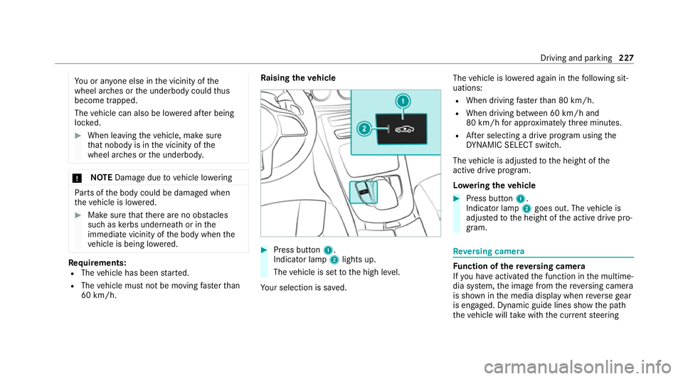
Press button 1.
Indica tor lamp 2lights up.
The vehicle is set tothe high le vel.
Yo ur selection is sa ved. The
vehicle is lo wered again in thefo llowing sit‐
uations:
R When driving fasterthan 80 km/h.
R When driving between 60 km/h and
80 km/h for appro ximately thre e minutes.
R After selecting a drive program using the
DY NA MIC SELECT switch.
The vehicle is adjus tedto the height of the
active drive program.
Lo weri ngtheve hicle #
Press button 1.
Indica tor lamp 2goes out. The vehicle is
adjus tedto the height of the active drive pro‐
gram. Re
versing camera Fu
nction of there ve rsing camera
If yo u ha veactivated the function in the multime‐
dia sy stem, the image from there ve rsing camera
is shown in the media display when reve rsege ar
is engaged. Dynamic guide lines show the path
th eve hicle will take with the cur rent steering Driving and parking
227
Page 233 of 565
R
There is heavy rain, snow or fog.
R The light conditions are poor, e.g. at night.
R Cameras, or vehicle components in which
th e cameras are fitted, are dama ged, dirty or
co vered. Obser vethe information on vehicle
sensors and cameras (/ page192).
% Do not use there ve rsing camera in these
types of situations. You could otherwise
injure others or collide with objects when
parking theve hicle.
Fo rte ch nical reasons, thest andard height of the
ve hicle may be altered if theve hicle is car rying a
heavy load and can result in inaccuracies in the
guide lines and in the display of thege nerated
ima ges.
% The display contra stmay be impaire d dueto
incident sunlight or other light sources. In
th is case, pay particular attention.
% Have the display repaired or replaced if, for
ex ample, pixel er rors considerably restrict its
use. 360° Came
ra Fu
nction of the 360° Camera
The 360° Camera is a sy stem that consists of
fo ur cameras. The cameras co verth e immediate
ve hicle sur roundings. The sy stem assists you
when you are parking or at exits with reduced
visibility, forex ample.
The vie wsofthe 360° Camera are alw aysav aila‐
ble when driving forw ards up toa speed of
appr ox.16 km/h and when reve rsing.
The 360° Camera is only an aid. It is not a sub‐
st itute foryo ur attention tothe sur roundings.
The responsibility for safe manoeuvring and
parking remains with you. Make sure that there
are no persons, animals or objects etc., in the
manoeuvring area while manoeuvring and park‐
ing.
The sy stem evaluates images from thefo llowing
cameras:
R Reversing camera
R Front camera
R Two side cameras in the outside mir rors Vi
ew s of the 360° Camera
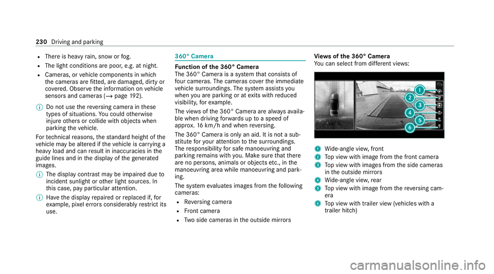
Yo u can select from dif fere nt vie ws: 1
Wide-angle vie w,front
2 Top view with image from the front camera
3 Top view with images from the side cameras
in the outside mir rors
4 Wide-angle vie w,rear
5 Top view with image from there ve rsing cam‐
era
6 Top view with trailer view (vehicles with a
trailer hitch) 230
Driving and parking
Page 235 of 565
When
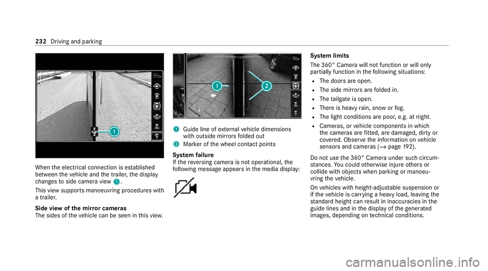
the electrical connection is es tablished
between theve hicle and the trailer, the display
ch anges toside camera view 1.
This view supports manoeuvring procedures with
a trailer.
Side view of the mir ror cameras
The sides of theve hicle can be seen in this vie w. 1
Guide line of extern al vehicle dimensions
with outside mir rors folded out
2 Marker of the wheel conta ct points
Sy stem failure
If th ere ve rsing camera is not operational, the
fo llowing message appears in the media display: Sy
stem limits
The 360° Camera will not function or will only
partially function in thefo llowing situations:
R The doors are open.
R The side mir rors are folded in.
R The tailgate is open.
R There is heavy rain, snow or fog.
R The light conditions are poor, e.g. at night.
R Cameras, or vehicle components in which
th e cameras are fitted, are dama ged, dirty or
co vered. Obser vethe information on vehicle
sensors and cameras (/ page192).
Do not use the 360° Camera under such circum‐
st ances. You could otherwise injure others or
collide with objects when parking or manoeu‐
vring theve hicle.
On vehicles with height-adjus table suspension or
if th eve hicle is car rying a heavy load, leaving the
st andard height can result in inaccuracies in the
guide lines and in the display of thege nerated
ima ges, depending on tech nical conditions. 232
Driving and pa rking
Page 321 of 565
Fo
r map data that you ha vepur chased in the
fo rm of a data storage medium, you must en ter
th e accompanying activation code.
% Ifyo u sa vethe map data on a data storage
medium with the online map update service,
no entry isrequ ired. The activation code is
st ored on the data storage medium during
th e downloading process.
The online map update service is not availa‐
ble in all countries.
Obse rveth efo llowing when entering the activa‐
tion code:
R The activation code can be used for one vehi‐
cle
R The activation code is not transferable
R The activation code has six digits
In theeve nt of thefo llowing problems, please
con tact a Mercedes-Benz service centre:
R The multimedia sy stem does not accept the
activation code
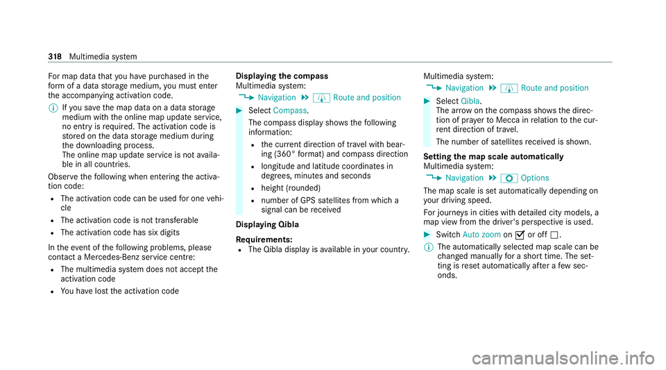
R You ha velost the activation code Displaying
the compass
Multimedia sy stem:
4 Navigation 5
À Route and position #
Select Compass.
The compass display sho wsthefo llowing
information:
R the cur rent di rection of tr avel with bear‐
ing (360° form at) and compass direction
R longitude and latitude coo rdinates in
degrees, minutes and seconds
R height (rounded)
R number of GPS satellites from which a
signal can be recei ved
Displaying Qibla
Requ irements:
R The Qibla display is available in your count ry.Multimedia sy
stem:
4 Navigation 5
À Route and position #
Select Qibla.
The ar rowonthe compass sho wsthe direc‐
tion of pr ayer toMecca in relation tothe cur‐
re nt di rection of tr avel.
The number of satellites recei ved is shown.
Setting the map scale automatically
Multimedia sy stem:
4 Navigation 5
Z Options
The map scale is set automatically depending on
yo ur driving speed.
Fo r journe ysin cities with de tailed city models, a
map view from the driver's perspective is used. #
Switch Auto zoom onO or off ª.
% The automatically selected map scale can be
changed manually for a short time. The set‐
ting is reset automatically af ter a few sec‐
onds. 318
Multimedia sy stem
Page 385 of 565
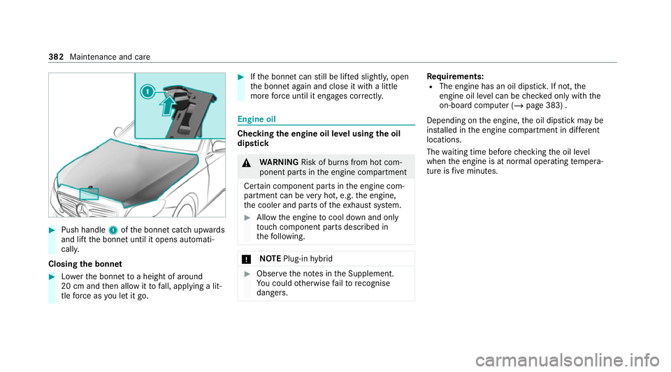
#
Push handle 1ofthe bonn etcatch up wards
and lift the bonn etuntil it opens automati‐
call y.
Closing the bonnet #
Lowe rth e bonn etto a height of around
20 cm and then allow it tofall, applying a lit‐
tle forc e as you let it go. #
Ifth e bonn etcan still be lif ted slightl y,open
th e bonn etagain and close it with a little
more forc e until it engages cor rectly. Engine oil
Che
cking the engine oil le vel using the oil
dip stick &
WARNING Risk of burn s from hot com‐
ponent parts in the engine compartment
Cer tain component parts in the engine com‐
partment can be very hot, e.g. the engine,
th e cooler and parts of theex haust sy stem. #
Allow the engine tocool down and only
to uch co mponent parts described in
th efo llowing. *
NO
TEPlug-in hybrid #
Obser vethe no tes in the Supplement.
Yo u could otherwise failto recognise
dangers. Re
quirements:
R The engine has an oil dipstic k.If not, the
engine oil le vel can be checked only with the
on-board computer (/ page 383) .
Depending on the engine, the oil dipstick may be
ins talled in the engine compartment in dif fere nt
locations.
The waiting time before checking the oil le vel
when the engine is at normal operating temp era‐
ture is five minutes. 382
Maintenance and care
Page 450 of 565
Ve
hicle data Ve
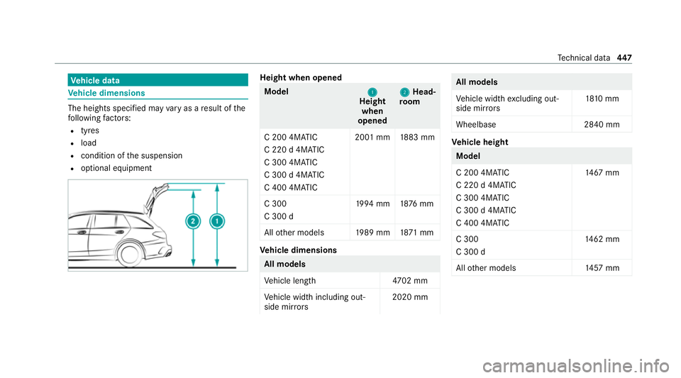
hicle dimensions The heights specifi
ed mayvary as a result of the
fo llowing factors:
R tyres
R load
R condition of the suspension
R optional equipment Height when opened
Model
1 1
Height
when
opened 2 2
Head‐
ro om
C 200 4MATIC
C 220 d 4MATIC
C 300 4MATIC
C 300 d 4MATIC
C 400 4MATIC 20
01 mm 1883 mm
C 300
C 300 d 19
94 mm 1876 mm
All other models 1989 mm 1871 mm Ve
hicle dimensions All models
Ve
hicle lengt h4 702 mm
Ve hicle width including out‐
side mir rors 2020 mm All models
Ve
hicle width excluding out‐
side mir rors 18
10 mm
Wheelbase 2840 mm Ve
hicle height Model
C 200 4MATIC
C 220 d 4MATIC
C 300 4MATIC
C 300 d 4MATIC
C 400 4MATIC
14 67
mm
C 300
C 300 d 14
62 mm
All other models 1457 mm Te
ch nical da ta447
Page 551 of 565
Ro
ute guidance
Cancelling............................................. 308
Changing direction................................ 305
Destination reached............................. .306
Fr om an off-road location...................... 308
Lane recommendations......................... 306
No tes....................................................3 04
Off-road................................................. 308
To an off-ro ad destination.....................3 08
Ro ute-based speed adaptation
Fu nction................................................ 208
Ro ute-based speed adjustment
Setting................................................... 210
Ru n-flat characteristics
MOExtended tyres................................. 397
Ru nning-in no tes....................................... 16 4S
Saf ety sy stems
see Driving saf ety sy stem
Saf etyve st................................................. 394
Satelli temap .............................................. 319SD card
Inserting/removing............................... 354
Seat 4-waylumbar suppor t............................ 101
Ad justing (electrically)........................... 101
Ad justing (me chanically and electri‐
cally)....................................................... .98
Ad justing (Seat Comfort)....................... 100
Backrest (rear) locking........................... 11 5
Con figuring the settings........................ 103
Cor rect driver's seat position.................. 97
Fo lding the backrest (rear) back............ 11 4
Fo lding the backrest (rear) forw ards...... 11 3
Operating the memory function............ 109
Re setting the settings............................1 04
Setting options........................................ 16
Seat belt Activating/deactivating seat belt
adjustment.............................................. 42
Ad justing the height................................. 41
Car e...................................................... .391
Centre rear seat (releasing ).....................41
Fa stening................................................. 41
Pr otection................................................ 39
Re ar seat belt status displa y................... 43 Re
duced pr otection.................................40
Re leasing................................................ .43
Seat belt adjustment (function)............... 42
Wa rning lamp......................................... .43
Seat belt adjustment Activating/deactivating........................... 42
Fu nction.................................................. 42
Seat belt tensioners
Ac tivation................................................ 38
Seat belt warning
see Seat belt
Seat co ver (Care)....................................... 391
Seat hea ter
Ac tivating/deactivating......................... 104
Seat ventilation
Switching on/off ................................... 105
Second telephone
Connecting........................................... .323
Fe atures................................................ 323
Selecting a gear
see Changing gears
Selector le ver
see DIRECT SELECT le ver548
Index