2020 MERCEDES-BENZ C-CLASS ESTATE battery
[x] Cancel search: batteryPage 132 of 565
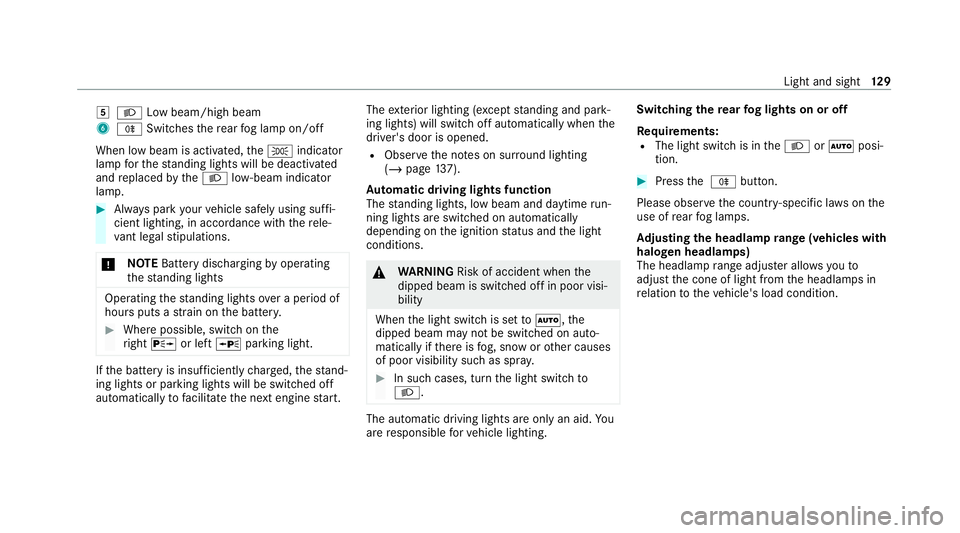
5
L Low beam/high beam
6 R Switches there ar fog lamp on/off
When low beam is activated, theT indicator
lamp forth est anding lights will be deactivated
and replaced bytheL low- beam indicator
lamp. #
Alw ays park your vehicle safely using suf fi‐
cient lighting, in acco rdance with there le‐
va nt le galst ipulations.
* NO
TEBattery discharging byoperating
th est anding lights Operating
thest anding lights over a period of
hours puts a stra in on the batter y. #
Where possible, switch on the
ri ght X or left Wparking light. If
th e battery is insuf ficiently charge d, thest and‐
ing lights or parking lights will be swit ched off
automatically tofacilitate the next engine start. The
exterior lighting (e xcept standing and park‐
ing lights) will swit choff automatically when the
driver's door is opened.
R Obser vethe no tes on sur round lighting
(/ page 137).
Au tomatic driving lights function
The standing lights, low beam and daytime run‐
ning lights are switched on au tomatically
depending on the ignition status and the light
conditions. &
WARNING Risk of accident when the
dipped beam is switched off in poor visi‐
bility
When the light switch is set toà ,the
dipped beam may not be switched on auto‐
matically if there is fog, snow or other causes
of poor visibility such as spr ay. #
In such cases, turn the light switch to
L . The automatic driving lights are only an aid.
Yo u
are responsible forve hicle lighting. Switching
there ar fog lights on or off
Re quirements:
R The light switch is in theL orà posi‐
tion. #
Press the R button.
Please obser vethe count ry-specific la wsonthe
use of rear fog lamps.
Ad justing the headlamp range (vehicles with
halogen headla mps)
The headlamp range adjus ter allows youto
adjust the cone of light from the headlamps in
re lation totheve hicle's load condition. Light and sight
12 9
Page 151 of 565
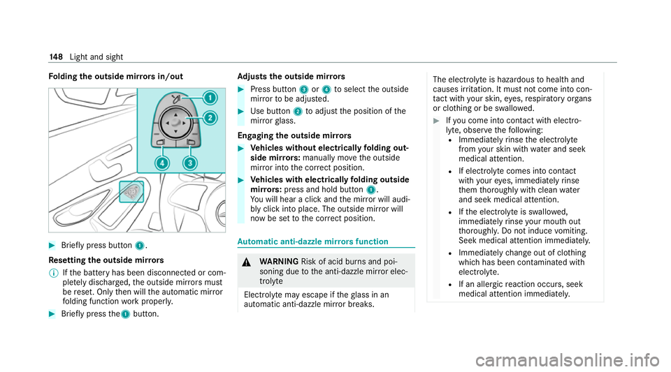
Fo
lding the outside mir rors in/out #
Brief lypress button 1.
Re setting the outside mir rors
% Ifth e battery has been disconnected or com‐
ple tely discharged, the outside mir rors must
be reset. Only then will the automatic mir ror
fo lding function workproperly. #
Brief lypress the1 button. Ad
justs the outside mir rors #
Press button 3or4 toselect the outside
mir rorto be adjus ted. #
Use button 2toadjust the position of the
mir rorgl ass.
Engaging the outside mir rors #
Vehicles without electrically folding out‐
side mir rors: manually mo vethe outside
mir ror into the cor rect position. #
Vehicles with electrically folding outside
mir rors:press and hold button 1.
Yo u will hear a click and the mir ror will audi‐
bly click into place. The outside mir ror will
now be set tothe cor rect position. Au
tomatic anti-dazzle mir rors function &
WARNING Risk of acid burn s and poi‐
soning due tothe anti-dazzle mir ror elec‐
trolyte
Electrolyte may escape if theglass in an
automatic anti-dazzle mir ror breaks. The electrolyte is hazardous
tohealth and
causes ir rita tion. It mu stnot come into con‐
ta ct with your skin, eyes,respiratory or gans
or clo thing or be swallo wed. #
Ifyo u come into contact with electro‐
ly te , obser vethefo llowing:
R Immediately rinse the electrolyte
from your skin with water and seek
medical attention.
R If electrolyte comes into contact
with your eyes, immediately rinse
th em thoroughly with clean water
and seek medical attention.
R Ifth e electrolyte is swallo wed,
immediately rinse your mouth out
th oroughl y.Do not induce vomiting.
Seek medical attention immediately.
R Immedia tely ch ange out of clo thing
which has been con taminated with
electrolyte.
R If an allergic reaction occurs, seek
medical attention immediatel y.14 8
Light and sight
Page 160 of 565
*
NO
TEBattery discharge caused bysta‐
tionary heater or stationary ventilation
operation Ope
rating thest ationary heater or stationary
ve ntilation drains the batter y. #
After heating or ventilating theve hicle
twice, drive for a longer period of time. Re
quirements:
R The fuel tank is filled toat least there ser ve
le ve l. #
Set the desired temp erature using thew
button (/ page151). #
Press the& button.
The red or blue indicator lamp on button will
light up or go out.
The colours of the indicator lamp ha vethefo l‐
lowing meanings:
R Blue: stationary ventilation is switched on.
R Red:thest ationary heater is swit ched on.
R Yello w: the departure time is preselected. The
stationary heater/ ventilation will switch off
au tomatically af ter 50 minutes.
Operation using the app: thest ationary
heater/ ventilation can also be operated via the
Mercedes me connect app. You can find fur ther
information in the separate Owner's Manual at
https://moba.i.daimler.com/mar kets/ece-r ow/
baix/cars/connectme/en_GB/#emotions/
St artseite.htm l.
Setting thest ationary heater/stationary ven‐
tilation via the multimedia sy stem
Multimedia sy stem:
4 Vehicle 5
b Climate control
5 Auxiliary heating
Yo u can pre-set thre e departure times for auto‐
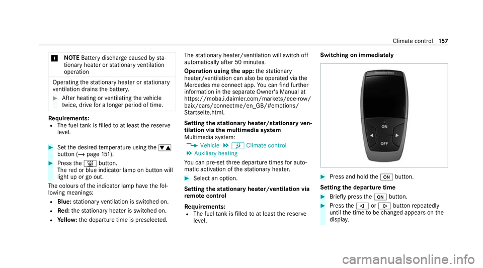
matic activation of thest ationary heater. #
Select an option.
Setting thest ationary heater/ventilation via
re mo tecont rol
Re quirements:
R The fuel tank is filled toat least there ser ve
le ve l. Switching on immedia
tely #
Press and hold theu button.
Setting the departu retime #
Brie fly press theu button. #
Press the, or. button repeatedly
until the time tobe changed appears on the
displa y. Climate cont
rol157
Page 162 of 565
+
ENVIRONMENTAL
NOTEEnvironmental
dama gedue toimproper disposal of bat‐
te ries Batteries conta
intoxic and cor ro‐
sive subs tances. #
Ta
ke dischar ged batteries to a
qu alified specialist workshop or to a
collection point for used batteries. Re
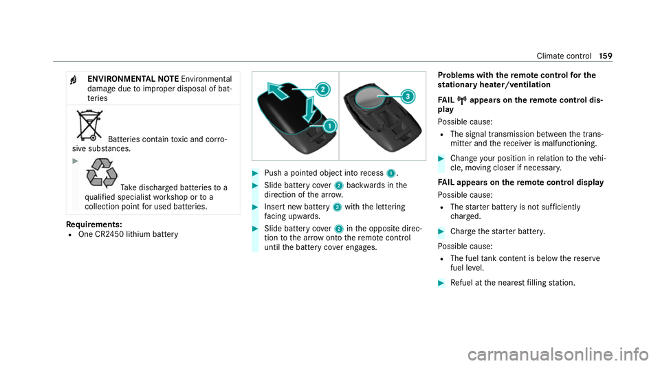
quirements:
R One CR2450 lithium battery #
Push a pointed object into recess 1. #
Slide battery co ver2 backwards in the
direction of the ar row. #
Insert new battery 3with the lettering
fa cing up wards. #
Slide battery co ver2 inthe opposite direc‐
tion tothe ar row onto there mo tecontrol
until the battery co ver engages. Problems with
there mo tecont rolfo r the
st ationary heater/ventilation
FA IL¨ ¨ appea rson there mo tecont rol dis‐
play
Po ssible cause:
R The signal transmission between the trans‐
mitter and there cei ver is malfunctioning. #
Change your position in relation totheve hi‐
cle, moving closer if necessar y.
FA IL appea rson there mo tecont rol display
Po ssible cause:
R The star ter battery is not suf ficiently
ch arge d. #
Char gethest ar ter batter y.
Po ssible cause:
R The fuel tank content is below there ser ve
fuel le vel. #
Refuel at the nearest filling station. Climate control
15 9
Page 166 of 565
St
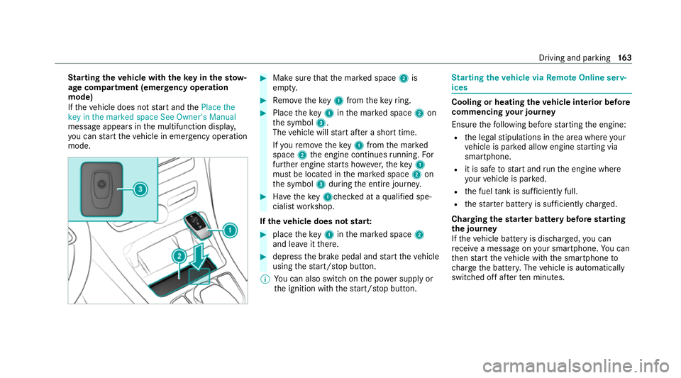
arting theve hicle with theke y in thesto w‐
age compa rtment (emer gency operation
mode)
If th eve hicle does not start and thePlace the
key in the marked space See Owner's Manual
message appears in the multifunction displa y,
yo u can start theve hicle in emer gency operation
mode. #
Makesure that the mar ked space 2is
em pty. #
Remo vetheke y1 from theke yring. #
Place theke y1 inthe mar ked space 2on
th e symbol 3.
The vehicle will start af ter a short time.
If yo ure mo vetheke y1 from the mar ked
space 2the engine continues running. For
fur ther engine starts ho wever,th eke y1
must be located in the mar ked space 2on
th e symbol 3during the entire journe y. #
Have theke y1ch ecked at a qualified spe‐
cialist workshop.
If th eve hicle does not star t: #
place theke y1 inthe mar ked space 2
and lea veitth ere. #
depress the brake pedal and start theve hicle
using thest art/ stop button.
% You can also swit chon the po wer supp lyor
th e ignition with thest art/ stop button. St
arting theve hicle via Remo teOnline serv‐
ices Cooling or heating
theve hicle interior before
commencing your journey
Ensure thefo llowing before starting the engine:
R the legal stipulations in the area where your
ve hicle is par ked allow engine starting via
smartphone.
R it is safe tostart and runth e engine where
yo ur vehicle is par ked.
R the fuel tank is su fficiently full.
R thest ar ter battery is suf ficiently charge d.
Charging thest ar ter battery be fore starting
th e jou rney
If th eve hicle battery is dischar ged, you can
re cei vea message on your smartphone. You can
th en start theve hicle with the smartphone to
ch arge the batter y.The vehicle is automatically
switched off af terte n minu tes. Driving and parking
16 3
Page 194 of 565
re
cei vea notification in the multimedia sy stem
when you swit chon the ignition.
Yo u will recei veinformation about thefo llowing
points:
R The area of theve hicle that may ha vebeen
damaged.
R The forc e of the impact.
The following situations can lead toinadver tent
acti vation:
R The pa rked vehicle is mo ved, e.g. in a two-
st or ey garage.
% Deactivate tow- aw ay protection in order to
pr eve nt inadver tent acti vation. If you deacti‐
va te tow- aw ay protection, collision de tection
will also be deactivated.
Sy stem limits
De tection may be restricted in thefo llowing sit‐
uations:
R theve hicle is damaged without impact, e.g. if
an outside mir ror is torn off or the paint is
damaged byakey
R an impact occurs at low speed R
the electric parking brake is not applied Note
s on parking up theve hicle If
yo u lea vetheve hicle par ked up for longer than
six weeks, it may suf fer dama gethro ugh disuse.
The 12V battery may also be impaired or dam‐
aged byheavy discharging.
% Further information can be obtained at a
qu alified specialist workshop.
* NO
TEPlug-in hybrid #
Obser vethe no tes about the high-volt‐
age battery in the Supplement. Yo u
could otherwise failto recognise dan‐
ge rs. St
andby mode (extension of the star ter bat‐
te ry 's period out of use) St
andby mode function
% This function is not available for all models. If
standby mode is activated, ene rgy loss will be
minimised during extended pe riods of non-oper‐
ation.
St andby mode is characterised bythefo llowing:
R The star ter battery is preser ved.
R The maximum non-operational time appears
inthe media displa y.
R The connection toonline services is inter rup‐
te d.
R The ATA (anti-theft alarm sy stem) is una vaila‐
ble.
R The interior pr otection and tow- aw ay protec‐
tion functions are not available.
R The function for de tecting collisions on a
pa rked vehicle is not available.
If th efo llowing conditions are fulfilled, standby
mode can be activated or deactivated using the
multimedia sy stem:
R The engine is switched off.
R The ignition is switched on.
Exceeding theve hicle's displa yed non-opera‐
tional time may cause inco nvenience, i.e. it can‐ Driving and pa
rking 191
Page 195 of 565
not be guaranteed
that thest ar ter battery will
re liably start the engine.
The star ter battery must be charge dfirs t in the
fo llowing situations:
R The vehicle's non-operational time must be
ex tended.
R The Battery charge insufficient for standby
mode messa geappears in the media displa y.
% Standby mode is automatically deactivated
when the ignition is switched on.
Ac tivating/deactivating standby mode
Multimedia sy stem:
4 Vehicle 5
î Vehicle settings
5 Standby mode
% This function is not available for all models. #
Activate Oor deacti vate ª the function.
When you activate the function, a prom pt
appears. #
Select Yes.
St andby mode is activated. Driving and driving saf
ety sy stems Driving sy
stems and your responsibility Yo
ur vehicle is equipped with driving sy stems
which assist you in driving, parking and manoeu‐
vring theve hicle. The driving sy stems are only
aids. They are not a substitute foryo ur attention
to the sur roundings and do not relie ve you of
yo ur responsibility per taining toroad traf fic la w.
The driver is alw aysre sponsible for maintaining
a safe dis tance totheve hicle in front, forve hicle
speed, for braking in good time and forst ay ing
in lane. Pay attention tothe tra ffic conditions at
all times and inter vene when necessary . Be
aw are of the limitations rega rding the safe use of
th ese sy stems.
Driving sy stems can neither reduce therisk of
accident if youfa ilto adapt your driving style nor
ove rride the la wsof ph ysics. They cannot alw ays
ta ke into account road, weather or traf fic condi‐
tions. In
fo rm ation on vehicle sensors and cameras Some driving and driving saf
ety sy stems use
cameras as well as radar or ultrasonic sensors
to monitor the area in front of, behind or next to
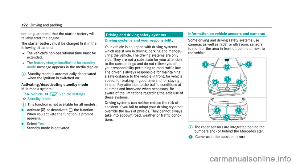
th eve hicle. %
The radar sensors are integ rated behind the
bumpers and/or behind the Mercedes star.
1 Cameras in the outside mir rors 19 2
Driving and pa rking
Page 249 of 565
Coupling/uncoupling a trailer
&
WARNING Risk of injury fromtheve hicle
le ve l being changed
Ve hicles with le vel control sy stem: the
ve hicle le vel may be changed unin tentional ly,
e.g. by ot her persons. You may become trap‐
ped if you couple up or uncouple a trailer
while theve hicle le vel is changing. In addi‐
tion, other people could become trapped if
th eir limbs are between theve hicle body and
th e tyres or underneath theve hicle.
When coupling up or uncoupling a trailer,
make sure that: #
The doors or tailgate are not opened or
closed. #
You do not initiate the le vel control sys‐
te m and do not operate theDY NA MIC
SELECT switch. #
Do not lock or unlock theve hicle. Re
quirements:
R The ball neck is extended and engaged in a
secu rely loc ked position. Tr
ailers with a 7-pin plug can be connec tedto
th eve hicle with thefo llowing adap ters:
R Adapter plug
R Adapter cable
The trailer will be cor rectly de tected bytheve hi‐
cle only if thefo llowing conditions are me t:
R The trailer is connected cor rectl y.
R The trailer lighting sy stem is in working
order.
The functions of thefo llowing sy stems will be
af fected bya cor rectly connected trailer:
R ESP ®
trailer stabilisation
R Active Lane Keeping Assist
R Parking Assist PARKTRONIC
R Active Parking Assist
R Blind Spot Assist or Active Blind Spot Assi st
R Drive AwayAssi st
R Cross Traf fic Alert
R Reversing camera
R 360° camera R
AIRMATIC
Coupling up a trailer
* NO
TEDama getothest ar ter battery due
to full discharge Charging
the trailer battery using the po wer
supply of the trailer can damage thest ar ter
batter y. #
Do not use theve hicle's po wer supply
to charge the trailer batter y. #
Remo vethe co ver cap from the ball head and
st ore it in a safe place. #
Position the trailer on a le vel sur face behind
th eve hicle and couple it up totheve hicle. 246
Driving and pa rking