2020 MERCEDES-BENZ AMG GT ROADSTER oil
[x] Cancel search: oilPage 118 of 381
Brake sy
stem Note
s onthe brake sy stem
The brake sy stem of your vehicle is designed for
heavy loads. Therefore, there may be noise when
braking. The loads in the entire brake sy stem
which occur when driving on a racetrack are sig‐
nificantly grea terth an those during normal oper‐
ation.
The increased brake forc es and temp eratures
when driving on a racetrack inhe rently lead to
inc reased wear of the brake sy stem.
Check the condition and geometry of the brake
co ver plate before using theve hicle on a race‐
trac k.
Obser vethe information on the cooling of com‐
ponents which are subject tostra in when oper‐
ated on a racetrack (/ page 114).
Braking with ABS
Re peated hard braking within the ABS control
ra nge causes higher temp eratures in the brake
sy stem than controlled braking shortly before
th e ABS control limit. Brakepad
wear
The inner and outer brakepads may also suf fer
"tapered wear". This could lead topoor pedal
fe el. Therefore, you must also check the condi‐
tion of the brakepads before and af ter use on a
ra cetrack as part of astandard check forwe ar.
Brake discs
Obse rveth e information on the cooling of com‐
ponents which are subject tostra in in racetrack
ope ration (/ page 114).
Depending on theve hicle's equipment, the AMG
ceramic high-per form ance composite braking
sy stem is fitted in your vehicle. The assessment
of we ar must therefore be car ried out using a
special measurement procedure. The brakes are
measured using the cur rent condition of the
ceramic composite material as a criteria for
assessing thewe ar ins tead of assessing the
re sidual thickness.
Depending on the type of brake disc, thefo llow‐
ing are combinations used tomeasu rethewe ar
of the brake discs:
R Carbon-ceramic brake disc -
Visual assessment of the brake disc for
mechanical dama ge
- Wear measurement using the indicator
fi eld me thod; alternatively using the Pro‐
ceq Carbo teq®
measu ring device (e.g. in
th e AMG Performance Center or at AMG
Tr ackda ys)
R Grey cast iron brake disc
- Visual check
- Crack test
- Wearthickness test
The ventilation holes on gr eycast iron friction
ri ngs of standard brake discs in particular could
become bloc kedby brake dust. Therefore, check
th eve ntilation holes be fore using theve hicle on
a ra cetrack and clean them if necessar y.If nec‐
essar y,also clean the drilled holes.
Brake fluid
Che ckthefo llowing properties of the brake fluid
before each use on a racetrack:
R Boiling point
R Fill le vel Driving and pa
rking 11 5
Page 120 of 381
Check
the tyres for dama geand the cor rect tyre
tread dep thboth before and af ter use on a race‐
trac k.Only then is it safe todrive on a racetrack
and on public roads.
As a result of the driving style and at high ambi‐
ent temp eratures, when driving on a racetrack it
may be necessary tocompensate forthe
inc rease in pressure in warm tyres byreleasing
air. Even forwa rm tyres, the specified tyre pres‐
sure may only be exceeded bymax. 0.5 bar.
Af terth e tyres ha vecooled down again, you
must readjust the tyre pressure in accordance
with the specifications in order todrive on public
ro ads. Suspension
Suspension settings
The
factory setting pr ovides a good compromise
fo r driving on public roads and on a racetrac k.
Ve hicle measurements
Even small changes tothe suspension settings
alter the driving characteristics of theve hicle. To
ensure optimal driving characteristics, the speci‐ fi
ed values and tolerances of the individual sus‐
pension settings must be complied with. The
driving characteristics of theve hicle may other‐
wise be undesirable.
Ve hicle measurements are requ ired in thefo llow‐
ing situations:
R theve hicle height has changed in relation to
th e optimised setting.
R theve hicle is frequently subjected tovery
high loads, e.g. when driving over kerbs.
Therefore, check theve hicle height at regular
inter vals and, if necessar y,per form vehicle
measurements.
Note s on suspension components
Despite regular checks, and rega rdless of
whe ther there leva nt suspension components
are in good condition, thefo llowing components
must be replaced af ter a cer tain amount of use
on thera cetrack:
R Wheel bolts (/ page 116)
R Wheel hubs including the wheel bearings Note
s on engine oil Check
the engine oil le vel before operating in
ra cetrack mode. DY
NA MIC SELECT switch Fu
nction of theDY NA MIC SELECT switch Use
theDY NA MIC SELECT switch tochange
between thefo llowing drive programs:
R o (Slippery): optimised pulling away and
driving characteristics in wint ryand slippe ry
ro ad conditions
R = (Individual): individual settings
R A (Comfort): comfortable and economi‐
cal driving style
R C (Sport): sporty driving style
R B (Sport Plus): particularly sporty driving
st yle
R I (RACE): driving like on a race track
The I (RACE) drive program may not be
used on normal roads. I (RACE) must on ly Driving
and parking 117
Page 135 of 381
Information on
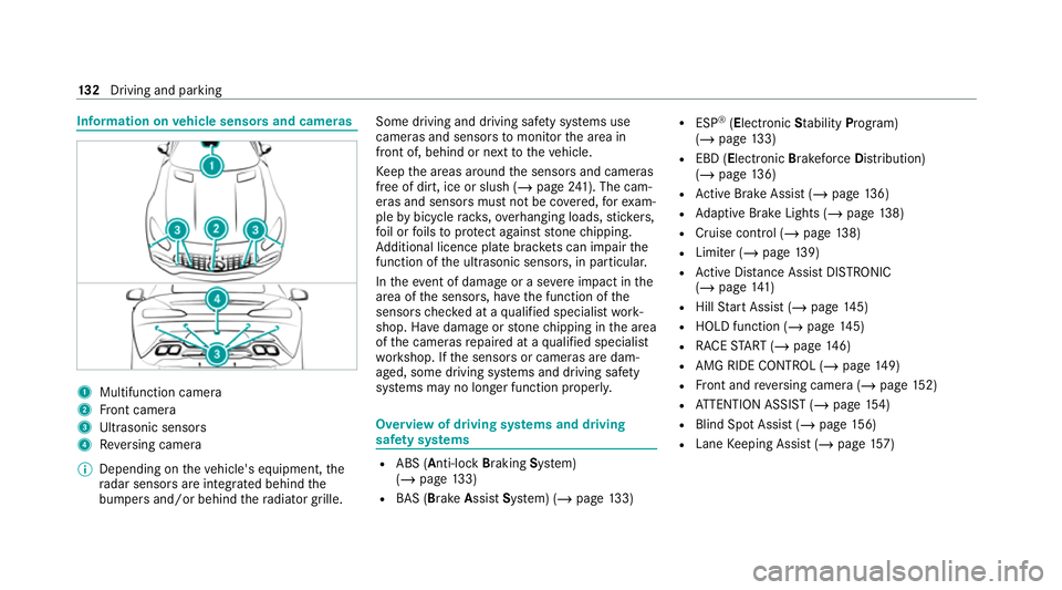
vehicle sensors and cameras 1
Multifunction camera
2 Front camera
3 Ultrasonic sensors
4 Reversing camera
% Depending on theve hicle's equipment, the
ra dar sensors are integ rated behind the
bumpers and/or behind thera diator grille. Some driving and driving saf
ety sy stems use
cameras and sensors tomonitor the area in
front of, behind or next totheve hicle.
Ke ep the areas around the sensors and cameras
free of dirt, ice or slush (/ page241). The cam‐
eras and sensors must not be co vered, forex am‐
ple bybicycle rack s, overhanging loads, sticke rs,
fo il or foils toprotect against stone chipping.
Ad ditional licence plate brac kets can impair the
function of the ultrasonic sensors, in particular.
In theeve nt of damage or a severe impact in the
area of the sensors, ha vethe function of the
sensors checked at a qualified specialist work‐
shop. Ha vedamage or stone chipping in the area
of the cameras repaired at a qualified specialist
wo rkshop. If the sensors or cameras are dam‐
aged, some driving sy stems and driving saf ety
sy stems may no longer function proper ly. Overview of driving sy
stems and driving
saf ety sy stems R
ABS (Anti-lo ckBra king System)
(/ page 133)
R BAS (Bra keAssist System) (/ page133) R
ESP ®
(Electronic Stability Program)
(/ page 133)
R EBD ( Electronic Brakeforc eDistribution)
(/ page 136)
R Active Brake Assi st (/ page 136)
R Adaptive Brake Lights (/ page138)
R Cruise control (/ page 138)
R Limi ter (/ page139)
R Active Dis tance Assi stDISTRONIC
(/ page 141)
R Hill Start Assist (/ page145)
R HOLD fu nction (/ page 145)
R RACE START (/ page 146)
R AMG RIDE CONTROL (/ page149)
R Front and reve rsing camera (/ page152)
R ATTENTION ASSIST (/ page154)
R Blind Spot Assi st (/ page 156)
R Lane Keeping Assist (/ page157) 13 2
Driving and pa rking
Page 185 of 381
R
Date
R Weather #
Select a desired lap.
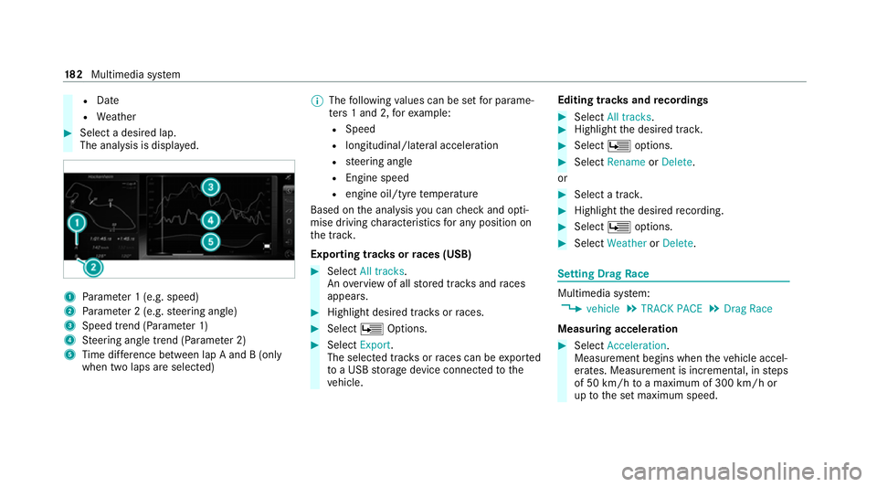
The anal ysis is displa yed. 1
Parame ter 1 (e.g. speed)
2 Parame ter 2 (e.g. steering angle)
3 Speed trend (Parame ter 1)
4 Steering angle trend (Parame ter 2)
5 Time dif fere nce between lap A and B (only
when two laps are selected) %
The following values can be set for parame‐
te rs 1 and 2, forex ample:
R Speed
R longitudinal/lateral acceleration
R steering angle
R Engine speed
R engine oil/tyre temp erature
Based on the anal ysis yo u can check and opti‐
mise driving characteristics for any position on
th e tra ck.
Exporting trac ksorraces (USB) #
Select All tracks.
An ove rview of all stored trac ksand races
appea rs. #
Highlight desired trac ksorraces. #
Select ÜOptions. #
Select Export.
The selected trac ksorraces can be expor ted
to a USB storage device connected tothe
ve hicle. Editing trac
ksand recordings #
Select All tracks. #
Highlight the desired trac k. #
Select Üoptions. #
Select Rename orDelete.
or #
Select a trac k. #
Highlight the desired recording. #
Select Üoptions. #
Select Weather orDelete. Setting Drag
Race Multimedia sy
stem:
4 vehicle 5
TRACK PACE 5
Drag Race
Measuring acceleration #
Select Acceleration.
Measurement begins when theve hicle accel‐
erates. Measurement is incremental, in steps
of 50 km/h toa maximum of 300 km/h or
up tothe set maximum speed. 18 2
Multimedia sy stem
Page 234 of 381
R
frequent operation in mountainous terrain or
on poor road sur faces
R when the engine is of ten le ftidling for long
periods
R operation in particula rly dusty conditions
and/or if air-recirculation mode is frequently
used
In these or similar operating conditions, ha vethe
interior air filter, engine air cleaner, engine oil
and oil filter etc. changed more frequent ly. The
tyres must be checked more frequently if the
ve hicle is operated under increased loads. Fur‐
th er information can be obtained at a qualified
specialist workshop. Battery disconnection periods
The ASS
YST PLUS se rvice inter val display
can only calculate the service due da tewhen
th e bat tery is connected. #
Notedown the service due date displa yed on
th e instrument display before disconnecting
th e battery (/ page 230). Engine compartment
Opening/closing
the bonnet &
WARNING Risk of accident due todriv‐
ing with the bonn etunlo cked
The bonn etmay open and block your vie w. #
Neverre lease the bonn etwhen driving. #
Before every trip, ensure that the
engine bonn etis loc ked. &
WARNING Risk of accident and inju ry
when opening and closing the bonn et
The bonnet may suddenly drop into the end
position.
There is a risk of injury for an yone in the bon‐
net's range of mo vement. #
Open or close the bonn etonly when
th ere is nobody in the bonn et's range of
mo vement. &
WARNING Danger of burn s when open‐
ing the bonn et
If yo u open the engine bonn etwhen the
engine has overheated or during a fire inthe
engine compartment, you could come into
contact with hot gases or other escaping
operating fluids. #
Before opening the bonn et, allow the
engine tocool down. #
Intheeve nt of a fire inthe engine com‐
partment, keep the engine bonn et
closed and call thefire service. &
WARNING Risk of injury duetomoving
parts
Components in the engine compartment may
continue running or start up sudden ly,even if
th e ignition is switched off.
Make sure of thefo llowing before per form ing
ta sks in the engine compartmen t: #
Switch the ignition off. Maintenance and care
231
Page 236 of 381
#
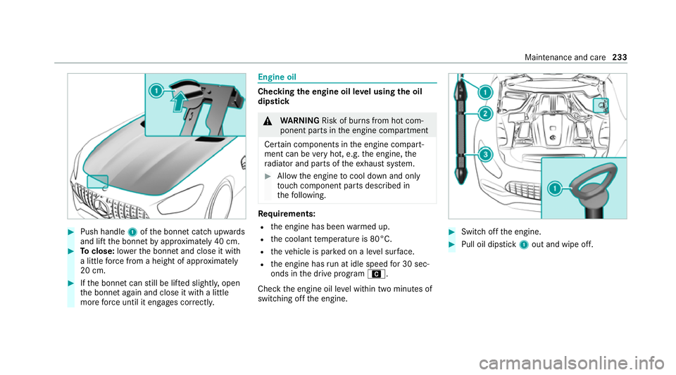
Push handle 1ofthe bonn etcatch up wards
and lift the bonn etby appr oximately 40 cm. #
Toclose: lowe rth e bonn etand close it with
a little forc e from a height of appr oximately
20 cm. #
Ifth e bonn etcan still be lif ted slightl y,open
th e bonn etagain and close it with a little
more forc e until it engages cor rectly. Engine oil
Che
cking the engine oil le vel using the oil
dip stick &
WARNING Risk of burn s from hot com‐
ponent parts in the engine compartment
Cer tain components in the engine compart‐
ment can be very hot, e.g. the engine, the
ra diator and parts of theex haust sy stem. #
Allow the engine tocool down and only
to uch co mponent parts described in
th efo llowing. Re
quirements:
R the engine has been warmed up.
R the coolant temp erature is 80°C.
R theve hicle is par ked on a le vel sur face.
R the engine has run at idle speed for 30 sec‐
onds in the drive program A.
Check the engine oil le vel within two minutes of
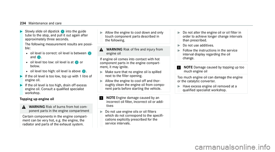
switching off the engine. #
Switch off the engine. #
Pull oil dipstick 1out and wipe off. Maintenance and care
233
Page 237 of 381
#
Slowly slide oil dipstick 1into the guide
tube tothestop, and pull it out again af ter
appr oximately thre e seconds.
The following measurement results are possi‐
ble:
R oil le vel is cor rect: oil le vel is between 2
and 3.
R oil le velto o low: oil le vel is at 3or
belo w.
R oil le velto o high: oil le vel is abo ve2 . #
Ifth e oil le vel is too lo w,top up with 1 litre of
engine oil. #
Ifth e oil le vel is too high, drain off excess
engine oil. Consult a qualified specialist
wo rkshop.
To pping up engine oil &
WARNING Risk of burn s from hot com‐
ponent parts in the engine compartment
Cer tain components in the engine compart‐
ment can be very hot, e.g. the engine, the
ra diator and parts of theex haust sy stem. #
Allow the engine tocool down and only
to uch co mponent parts described in
th efo llowing. &
WARNING Risk offire and injury from
engine oil
If engine oil comes into con tact with hot
component parts in the engine compart‐
ment, it may ignite. #
Make sure that no engine oil is spilled
next tothefiller opening. #
Allow the engine tocool off and thor‐
oughly clean the engine oil from compo‐
nent parts before starting theve hicle. *
NO
TEEngine damage causedbyan
incor rect oil filter, incor rect oil or addi‐
tives #
Do not use engine oils or oil filters
which do not cor respond tothe specifi‐
cations explicitly prescribed forthe
service inter vals. #
Do not alter the engine oil or oil filter in
order toachie velonger change inter vals
th an presc ribed. #
Do not use additives. #
Follow the instructions in the service
inter val display rega rding the oil
ch ange. *
NO
TEDama gecaused bytopping up too
much engine oil To
o much engine oil can damage the engine
or the catalytic con verter. #
Have excess engine oil remo ved at a
qu alified specialist workshop. 234
Maintenance and care
Page 238 of 381
#
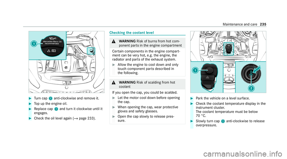
Turn cap 1anti-clockwise and remo veit. #
Top up the engine oil. #
Replace cap 1and turn it clockwise until it
engages. #
Check the oil le vel again (/ page 233). Checking
the coolant le vel &
WARNING Risk of burn s from hot com‐
ponent parts in the engine compartment
Cer tain components in the engine compart‐
ment can be very hot, e.g. the engine, the
ra diator and parts of theex haust sy stem. #
Allow the engine tocool down and only
to uch co mponent parts described in
th efo llowing. &
WARNING Risk of scalding from hot
coolant
If yo u open the cap, you could be scalded. #
Let the mo tor cool down before opening
th e cap. #
When opening the cap, wear pr otective
gl ove s and saf etygl asses. #
Open the cap slowly torelease pres‐
sure. #
Park theve hicle on a le vel sur face. #
Check the coolant temp erature display in the
instrument clus ter.
The coolant temp erature must be below
70 °C. #
Slowly turn cap 1anti-clockwise torelease
ove rpressure. Maintenance and care
235