Page 398 of 516
3986-3. Do-it-yourself maintenance
4Remove the light bulb.
5 Install a new light bulb and then
install the bulb base to the light unit
by inserting it and turning it clock-
wise.
After installing the bulb base, wiggle it
lightly to make sure it is securely installed
and turn the lights on to visually check that
there is no light lea king from between the
bulb base and light unit.
6 For the right side only: Fix the
washer fluid inlet.
1 Align the tab position and install
washer fluid inlet.
2 Fasten the bolt.
Page 400 of 516
4006-3. Do-it-yourself maintenance
tape to the taillight unit and fold the
excess in half.
2 Hold the folded portion and pull it
toward the rear of the vehicle to
remove the light unit.
5 Turn the bulb base counterclock-
wise and remove it.
6 Remove the light bulb.
7 Install a new light bulb and then
install the bulb base to the light unit
by inserting it and turning it clock-
wise.
After installing the bulb base, wiggle it
lightly to make sure it is securely installed
and turn on the rear turn signal lights to
visually check that ther e is no light leaking from between the bulb
base and light unit.
8Install the light unit.
Align the tabs and push the light unit-
toward the front of the vehicle to install it.
9Install the 2 screws.
Page 401 of 516
4016-3. Do-it-yourself maintenance
6
Maintenance and care
10Install the cover.
11 Remove the protective tape.
■Back-up lights (bulb type)
1 Open the back door and remove
the cover.
Using a flathead screwdriver, remove the
cover.
To prevent scratching to the vehicle, wrap
the tip of the flathead screwdriver with a
cloth, etc.
2 Turn the bulb base counterclock-
wise and remove it. 3
Remove the light bulb.
4 Install a new light bulb and then
install the bulb base to the light unit
by inserting it and turning it clock-
wise.
After installing the bulb base, wiggle it
lightly to make sure it is securely installed
and turn on the back-up lights to visually
check that there is no light leaking from
between the bulb ba se and light unit.
5Install the cover.
Align the tabs of the cover with the grooves
and install the cover.
Page 430 of 516
4307-2. Steps to take in an emergency
RX350
1 Secure the deck board using the
hook. ( P.324)
2 Loosen the center fastener that
secures the spare tire.
RX350L
1 Remove the deck board.
2 Remove the cover.
3 Attach the adapter socket to the
spare tire clamp bolt. 4
Assemble the jack handle exten-
sion.
5 Connect the jack handle to the
adapter socket. Turn the jack han-
dle counterclockwise.
The tire will be lowered completely to the
ground.
Turn the jack handle slowly to lower the
spare tire. If the handle is turned quickly,
the wire cable may come off the shaft
inside the unit and the tire may not be low-
ered.
If the spare tire cannot be lowered:
P.432
Taking out the spare tire
Page 432 of 516

4327-2. Steps to take in an emergency
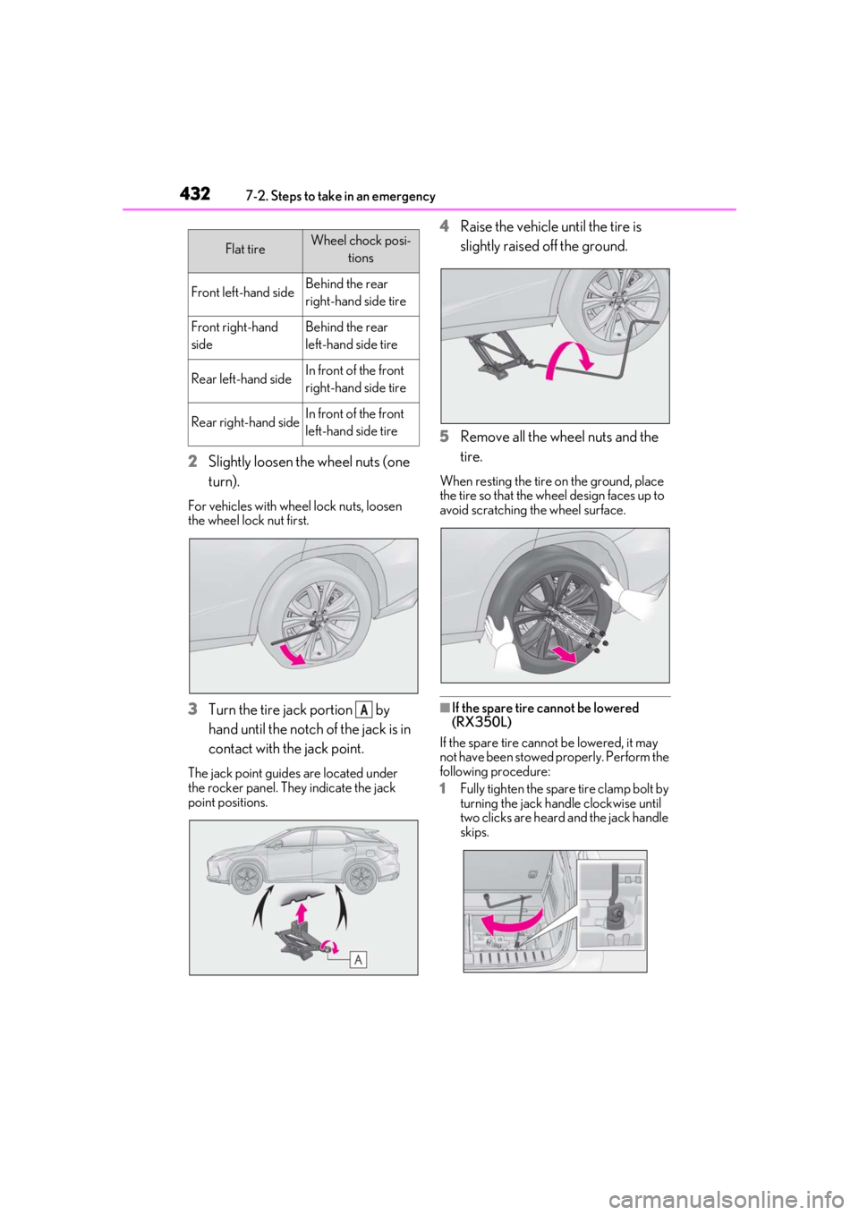
2Slightly loosen the wheel nuts (one
turn).
For vehicles with wheel lock nuts, loosen
the wheel lock nut first.
3Turn the tire jack portion by
hand until the notch of the jack is in
contact with the jack point.
The jack point guides are located under
the rocker panel. They indicate the jack
point positions.
4Raise the vehicle until the tire is
slightly raised off the ground.
5 Remove all the wheel nuts and the
tire.
When resting the tire on the ground, place
the tire so that the wheel design faces up to
avoid scratching the wheel surface.
■If the spare tire cannot be lowered
(RX350L)
If the spare tire cannot be lowered, it may
not have been stowed properly. Perform the
following procedure:
1 Fully tighten the spare tire clamp bolt by
turning the jack handle clockwise until
two clicks are heard and the jack handle
skips.
Flat tireWheel chock posi-
tions
Front left-hand sideBehind the rear
right-hand side tire
Front right-hand
sideBehind the rear
left-hand side tire
Rear left-hand sideIn front of the front
right-hand side tire
Rear right-hand sideIn front of the front
left-hand side tire
A
Page 433 of 516

4337-2. Steps to take in an emergency
7
When trouble arises
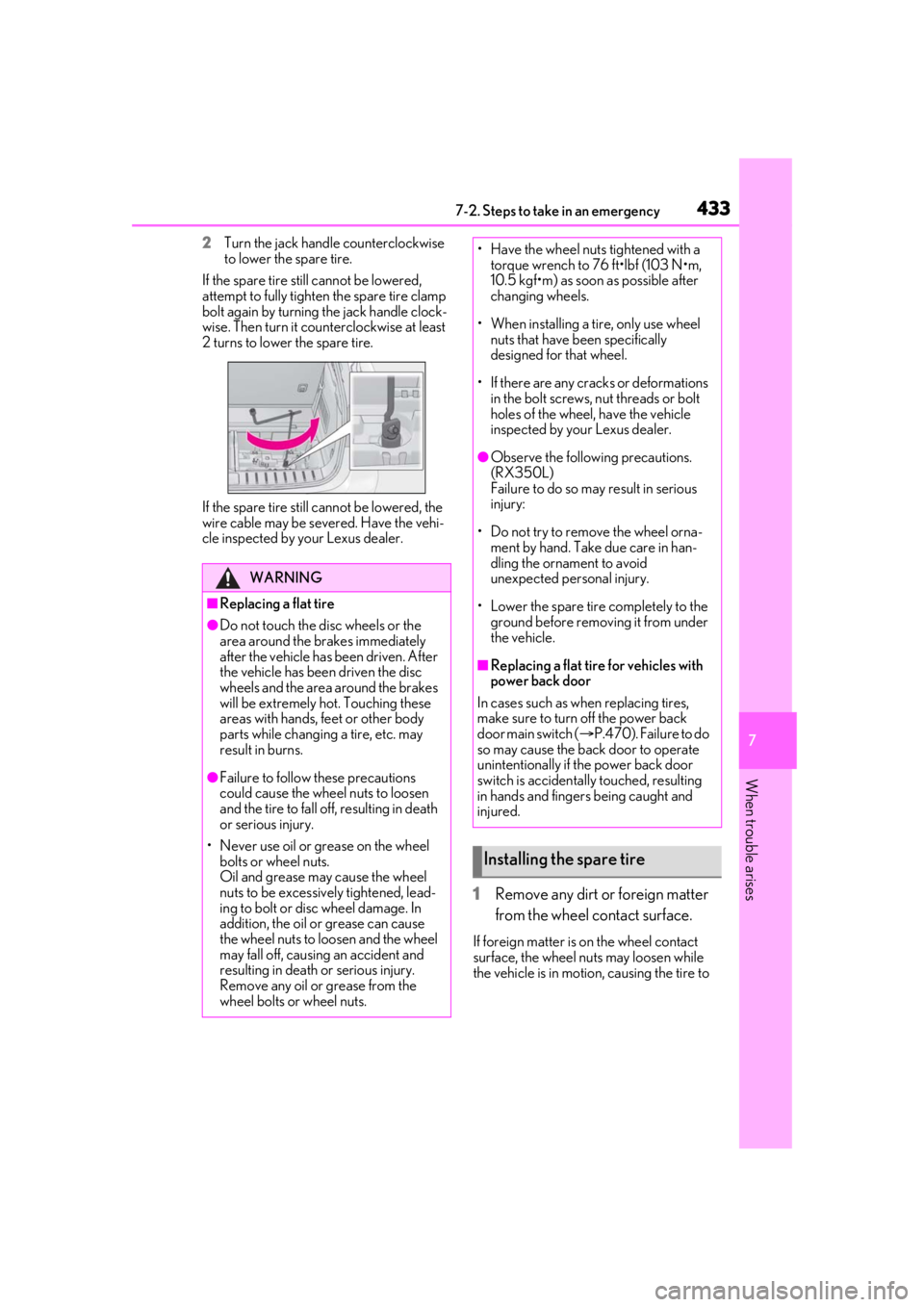
2Turn the jack handle counterclockwise
to lower the spare tire.
If the spare tire still cannot be lowered,
attempt to fully tighten the spare tire clamp
bolt again by turning the jack handle clock-
wise. Then turn it coun terclockwise at least
2 turns to lower the spare tire.
If the spare tire still ca nnot be lowered, the
wire cable may be seve red. Have the vehi-
cle inspected by your Lexus dealer.
1 Remove any dirt or foreign matter
from the wheel contact surface.
If foreign matter is on the wheel contact
surface, the wheel nuts may loosen while
the vehicle is in motion, causing the tire to
WARNING
■Replacing a flat tire
●Do not touch the disc wheels or the
area around the brakes immediately
after the vehicle has been driven. After
the vehicle has been driven the disc
wheels and the area around the brakes
will be extremely hot. Touching these
areas with hands, feet or other body
parts while changing a tire, etc. may
result in burns.
●Failure to follow these precautions
could cause the wheel nuts to loosen
and the tire to fall of f, resulting in death
or serious injury.
• Never use oil or grease on the wheel bolts or wheel nuts.
Oil and grease may cause the wheel
nuts to be excessively tightened, lead-
ing to bolt or disc wheel damage. In
addition, the oil or grease can cause
the wheel nuts to loosen and the wheel
may fall off, causing an accident and
resulting in death or serious injury.
Remove any oil or grease from the
wheel bolts or wheel nuts.
• Have the wheel nuts tightened with a torque wrench to 76 ft•lbf (103 N•m,
10.5 kgf•m) as soon as possible after
changing wheels.
• When installing a tire, only use wheel nuts that have been specifically
designed for that wheel.
• If there are any cracks or deformations in the bolt screws, nut threads or bolt
holes of the wheel, have the vehicle
inspected by your Lexus dealer.
●Observe the following precautions.
(RX350L)
Failure to do so may result in serious
injury:
• Do not try to remove the wheel orna- ment by hand. Take due care in han-
dling the ornament to avoid
unexpected personal injury.
• Lower the spare tire completely to the ground before removing it from under
the vehicle.
■Replacing a flat tire for vehicles with
power back door
In cases such as when replacing tires,
make sure to turn off the power back
door main switch ( P.470). Failure to do
so may cause the back door to operate
unintentionally if th e power back door
switch is accidentally touched, resulting
in hands and fingers being caught and
injured.
Installing the spare tire
Page 435 of 516
4357-2. Steps to take in an emergency
7
When trouble arises
and holding bracket through
the wheel opening.
3 Fully depress the secondary latch
and install the bracket to the
hoist assembly . 4
Lay the tire on the ground with the
outer surface (valve stem) facing
up.
5 Before raising the tire, make sure
that the hoist assembly is perpen-
dicular to the wheel opening. (Try to
place the tire directly beneath the
vehicle, near where the wire cable
is hanging from.)
Valve stem
6 Using the jack handle and adapter
socket, tighten the tire clamp bolt
by turning it clockwise until the tire
is in the correct position and two
clicks are heard as the jack handle
skips.CB
AB
C
A
Page 471 of 516
4718-2. Customization
8
Vehicle specifications
■Gauges, meters and multi-information display (P.70, 75, 79)
*1: For details about each function: P.83
Function*1Default settingCustomized setting
LanguageEnglishFrenchOO—Spanish
Units*2miles (MPG)
km (km/L)
OO—km (L/100km)
miles (MPG Impe-
rial)
Drive information 1
Current fuel con-sumption
Customizable items: P.80—O—
Average fuel econ-
omy (after reset)
Drive information 2
Distance (driving range)
Average vehicle
speed (after reset)
Drive information 3
Average fuel econ- omy (after refuel)
Elapsed time (after start)
Clock12-hour display24-hour display—O—
Pop-up displayOnOff—O—
Accent color*3Color 1Color 2OO—
Needle*4Color 1Color 2—O—Color 3
Rev indicator*45000 r/min.
2000 - 6500 r/min.
—O—
Off
Rev peak*4OnOff—O—
Eco Driving Indicator LightOnOff—O—
Suggestion functionOnOff——O
ABC