Page 247 of 597

4109
Features of your vehicle
✽ ✽NOTICE
• Do not disassemble a front view
camera temporarily for tinted
window or attaching any types of
coatings and accessories. If you
disassemble the camera and
assemble it again, take your vehi-
cle to an authorized Kia dealer
and have the system checked to
need a calibration.
• When you replace or reinstall the windshield glass, take your vehicle
to an authorized Kia dealer and
have the system checked.
• Be careful that water does not get into the High Beam Assist unit and
do not remove or damage related
parts of the High Beam Assist sys-
tem.
• Do not place objects on the dash- board that reflect light such as
mirrors, white paper, etc. The sys-
tem may not be able to function if
sunlight is reflected. (Continued)(Continued)
• At times, the High Beam Assist
may not operate due to system
limitations. The system is for your
convenience only. It is the respon-
sibility of the driver to use safe
driving practices and always
check the road conditions for your
safety.
• When the system does not operate normally, change the lamp posi-
tion manually between the high
beam and low beam.
Turn signals and lane change
signals
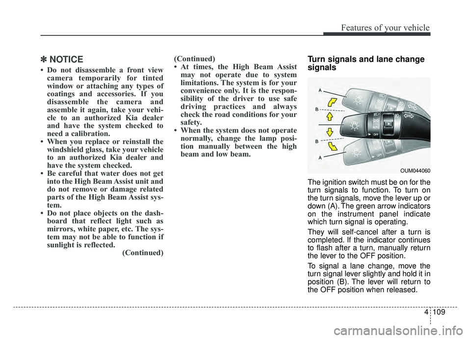
The ignition switch must be on for the
turn signals to function. To turn on
the turn signals, move the lever up or
down (A). The green arrow indicators
on the instrument panel indicate
which turn signal is operating.
They will self-cancel after a turn is
completed. If the indicator continues
to flash after a turn, manually return
the lever to the OFF position.
To signal a lane change, move the
turn signal lever slightly and hold it in
position (B). The lever will return to
the OFF position when released.
OUM044060
Page 256 of 597

Features of your vehicle
118
4
If you want to defrost and defog the
front windshield, refer to “Windshield
defrosting and defogging” in this sec-
tion.
Rear window defroster
The defroster heats the window to
remove frost, fog and thin ice from
the rear window, while the engine is
running.
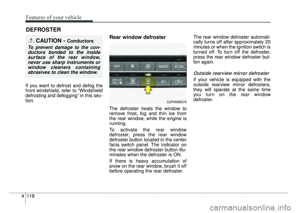
To activate the rear window
defroster, press the rear window
defroster button located in the center
facia switch panel. The indicator on
the rear window defroster button illu-
minates when the defroster is ON.
If there is heavy accumulation of
snow on the rear window, brush it off
before operating the rear defroster. The rear window defroster automati-
cally turns off after approximately 20
minutes or when the ignition switch is
turned off. To turn off the defroster,
press the rear window defroster but-
ton again.
Outside rearview mirror defroster
If your vehicle is equipped with the
outside rearview mirror defrosters,
they will operate at the same time
you turn on the rear window
defroster.
DEFROSTER
CAUTION - Conductors
To prevent damage to the con-
ductors bonded to the insidesurface of the rear window,never use sharp instruments orwindow cleaners containingabrasives to clean the window.
OJFH045074
Page 259 of 597
4121
Features of your vehicle
✽ ✽NOTICE
Never place anything over the sensor
located on the instrument panel to
ensure better control of the heating
and cooling system.
Manual heating and air condi-
tioning
The heating and cooling system can
be controlled manually by pressing
buttons or turning knob(s) other than
the AUTO button. In this case, the
system works sequentially according
to the order of buttons or knob(s)
selected.
1. Start the engine.
2. Set the mode to the desired posi-
tion.
For improving the effectiveness of
heating and cooling;- Heating:
- Cooling:
3. Set the temperature control to the desired position. 4. Set the air intake control to the
outside (fresh) air position.
5. Set the fan speed control to the desired speed.
6. If air conditioning is desired, turn the air conditioning system on.
Press the AUTO button in order to
convert to full automatic control of
the system.
OJFHP048086L
■Type A
■Type B
OJFA045086
Page 261 of 597

4123
Features of your vehicle
Face-Level (B, D)
Air flow is directed toward the upper
body and face. Additionally, each
outlet can be controlled to direct the
air discharged from the outlet.
Bi-Level (B, C, D, E, F)
Air flow is directed towards the face
and the floor.
Floor-Level (A, C, D, E, F)
Most of the air flow is directed to the
floor, with a small amount of the air
being directed to the windshield and
side window defrosters. Floor/Defrost-Level
(A, C, D, E, F)
Most of the air flow is directed to the
floor and the windshield with a small
amount directed to the side window
defrosters.
✽ ✽ NOTICE - 2nd row outlet
vents (E,F)
• The air flow of the 2nd row outlet vents is controlled by the front cli-
mate control system and delivered
through the inside air duct of the
floor (E, F).
• The air flow of the 2nd row outlet vents (E, F) may be weaker than
the instrument panel vents for the
long air duct.
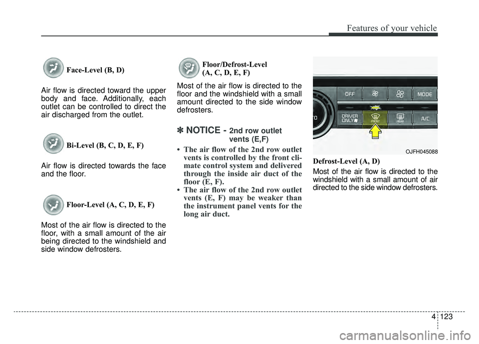
Defrost-Level (A, D)
Most of the air flow is directed to the
windshield with a small amount of air
directed to the side window defrosters.
OJFH045088
Page 262 of 597

Features of your vehicle
124
4
Instrument panel vents
The outlet vents can be opened or
closed separately using the thumb-
wheel (if equipped).
Also, you can adjust the direction of
air delivery from these vents using
the vent control lever as shown.
Temperature control
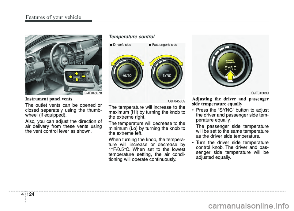
The temperature will increase to the
maximum (HI) by turning the knob to
the extreme right.
The temperature will decrease to the
minimum (Lo) by turning the knob to
the extreme left.
When turning the knob, the tempera-
ture will increase or decrease by
1°F/0.5°C. When set to the lowest
temperature setting, the air condi-
tioning will operate continuously. Adjusting the driver and passenger
side temperature equally
Press the “SYNC” button to adjust
the driver and passenger side tem-
perature equally.
The passenger side temperature
will be set to the same temperature
as the driver side temperature.
Turn the driver side temperature control knob. The driver and pas-
senger side temperature will be
adjusted equally.
OJF045078
■Driver’s side■Passenger’s side
OJF045089
OJF045090
Page 412 of 597

5117
Driving your vehicle
LKA operation
To activate/deactivate the LKA:
With the ignition switch in the ON
position, press the LKA button locat-
ed on the instrument panel on the
lower left hand side of the driver.
The indicator in the cluster display
will initially illuminate white.
If the indicated (white) was activated
in the previous ignition cycle, the
system will remain activated.
If you press the LKA button again,
the indicator on the cluster display
will go off.
OJFHP058308
(Continued)
The system is designed todetect lane markers using a
front view camera. If the lane
markers are hard to detect,
then the system may be limit-
ed. Always be cautious when
using the system.
When the lane markers are hard to detect, please refer to
“Driver’s Attention”.
Do not remove or damage the related parts of LKA.
Do not place objects on the dashboard that reflects light
such as mirrors, white paper,
etc. This may prevent the LKA
system from functioning
properly.
You may not hear warning sound of LKA if the audio vol-
ume is high.
(Continued)(Continued)
If you to drive with your handsoff the steering wheel, the
LKA will stop controlling the
steering wheel after the hands
off alarm. If you drive with
your hands on the steering
wheel again the control will be
activated again.
If the vehicle speed is high, steering torque for assistance
will not be enough to keep
your vehicle within the lane. If
so, the vehicle may move out
of its lane. Obey speed limit
when using LKA.
If you attach objects to the steering wheel, the system
may not assist steering.
If you attach objects to the steering wheel, hands off
alarm may not work properly.
Page 524 of 597

Maintenance
56
7
If you do not have a spare, use a
fuse of the same rating from a circuityou may not need for operating thevehicle, such as the power outletfuse.
If the head lamp, turn signal lamp,
stop signal lamp, fog lamp, DRL, tail
lamp, High Mounted Stop Lamp do
not work and the fuses are OK,
check the fuse panel in the engine
compartment. If a fuse is blown, it
must be replaced.
✽ ✽ NOTICE
If the headlamp, fog lamp, turn sig-
nal lamp, or tail lamp malfunction
even without any problem to the
lamps, have the vehicle checked by
an authorized Kia dealer.
Fuse switch
Always set the fuse switch to the ON
position before using the vehicle.
If you move the switch to the OFF
position, some items such as audio
and the digital clock must be reset
and transmitter (or smart key) may
not work properly. When the switch is
Off, the caution indicator will be dis-
played on the instrument cluster.
Always place the fuse switch in the
ON position while driving the vehicle.
If the switch is located in the “OFF”
position, a caution indicator will be
displayed in the cluster.
OJF075024
CAUTION - Fuse Panel
Covers
Set all switches to ON before
driving.
If the vehicle is going to be unused for over 1 month, setall switches to OFF to preventthe batteries from draining.
The contact points of the switches may wear out withexcessive use. Please refrainfrom excessive use of theswitches (except for long-termparking for over 1 month).
Page 528 of 597

Maintenance
60
7
Instrument panel (Driver’s side fuse panel)
Fuse NameFuse ratingCircuit Protected
MODULE 710ASurround View Monitor Unit, Front Air Ventilation Seat Control Module, Front Seat Warmer Control Module,
Rear Seat Warmer Control Module
MODULE 510AA/C Control Module, Electro Chromic Mirror, Driver IMS Module, Head Lamp LH/RH, Auto Head Lamp
Leveling Device Module, Fuel Lid & Trunk Open Switch, Shift Lever Indicator, Front Air Ventilation Seat
Control Module, Front Seat Warmer Control Module, Rear Seat Warmer Control Module
MODULE 610ABCM, Smart Key Control Module
A/CON10AA/C Control Module, E/R Junction Block (RLY. 4 - Blower Relay), Ionizer, Active Incar Sensor, Electronic A/C
Compressor
START10ATransmission Range Switch, Smart Key Control Module
A/BAG15ASRS Control Module, Passenger Occupant Detection Sensor
MODULE 310ABCM, Stop Lamp Switch, AFLS Unit, Keyboard, VESS Unit, A/V & Navigation Head Unit, Sport Mode
Switch
MODULE 410AConsole Switch, Blind-spot Collision Warning Radar LH/RH, Parking Assist Control Module, Smart Cruise
Control Unit, Lane Keeping Assist Module, Active Air Flap Unit, Electric Parking Brake Module, BMS Control
Module
INTERIOR LAMP10ATrunk Room Lamp, Driver/Passenger Door Lamp, Glove Box Lamp, Driver/Passenger Smart Key Outside
Handle, Front Vanity Lamp Switch LH/RH, Overhead Console Lamp, Rear Personal Lamp LH/RH,
Driver/Passenger Foot Lamp, Room Lamp, Center Personal Lamp