Page 257 of 687

Features of your vehicle
120
4
When driving downhill or uphill.
When only part of the vehicle in
front is visible on a crossroad or
curved road.
When there is a traffic light, reflect- ing sign, flashing sign or mirror.
When the road conditions are bad such as being wet or covered with
snow.
When the front vehicle’s head- lamps are off but the fog lamps on.
When a vehicle suddenly appears from a curve.
When the vehicle is tilted from a flat tire or being towed.
When the Lane Keeping Assist system warning light illuminates. (if
equipped)✽ ✽ NOTICE
• Do not place any accessories,
stickers or tint the windshield.
• Have the windshield glass replaced from an authorized dealer.
• Do not remove or damage related parts of High Beam Assist system.
• Be careful that water doesn’t get into the High Beam Assist unit.
• Do not place objects on the dash- board that reflect light such as
mirrors, white paper, etc. The sys-
tem may malfunction if sunlight is
reflected.
• At times, High Beam Assist sys- tem may not work properly,
always check the road conditions
for your safety. When the system
does not operate normally, manu-
ally change between the high
beam and low beam.
Turn signals and lane change
signals
The ignition switch must be on for the
turn signals to function. To turn on
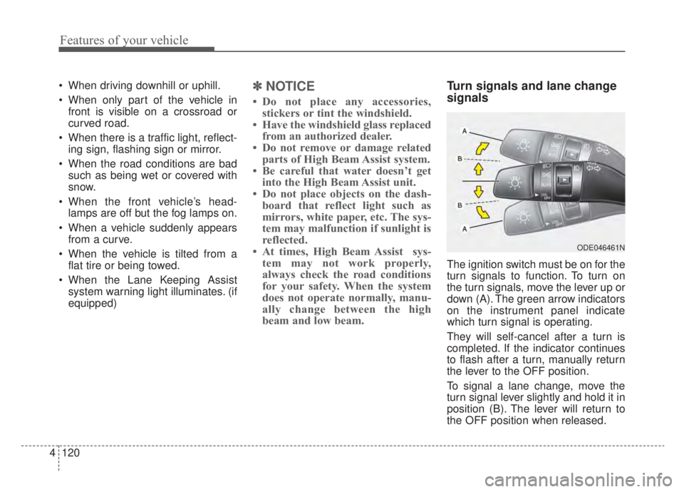
the turn signals, move the lever up or
down (A). The green arrow indicators
on the instrument panel indicate
which turn signal is operating.
They will self-cancel after a turn is
completed. If the indicator continues
to flash after a turn, manually return
the lever to the OFF position.
To signal a lane change, move the
turn signal lever slightly and hold it in
position (B). The lever will return to
the OFF position when released.
ODE046461N
Page 267 of 687

Features of your vehicle
130
4
If you want to defrost and defog the
front windshield, refer to “Windshield
defrosting and defogging” in this sec-
tion.
Rear window defroster
The defroster heats the window to
remove frost, fog and thin ice from
the rear window, while the engine is
running. To activate the rear window
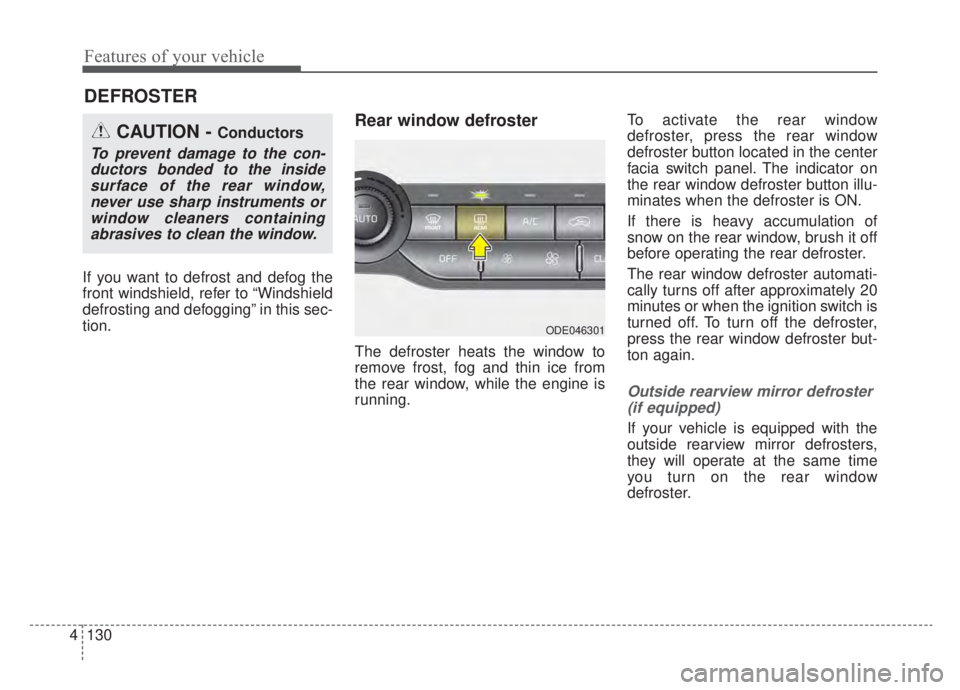
defroster, press the rear window
defroster button located in the center
facia switch panel. The indicator on
the rear window defroster button illu-
minates when the defroster is ON.
If there is heavy accumulation of
snow on the rear window, brush it off
before operating the rear defroster.
The rear window defroster automati-
cally turns off after approximately 20
minutes or when the ignition switch is
turned off. To turn off the defroster,
press the rear window defroster but-
ton again.
Outside rearview mirror defroster
(if equipped)
If your vehicle is equipped with the
outside rearview mirror defrosters,
they will operate at the same time
you turn on the rear window
defroster.
DEFROSTER
CAUTION - Conductors
To prevent damage to the con-ductors bonded to the insidesurface of the rear window,never use sharp instruments orwindow cleaners containingabrasives to clean the window.
ODE046301
Page 270 of 687
4133
Features of your vehicle
✽ ✽NOTICE
Never place anything over the sensor
located on the instrument panel to
ensure better control of the heating
and cooling system.
ODEP049414
Page 272 of 687

4135
Features of your vehicle
Mode selection
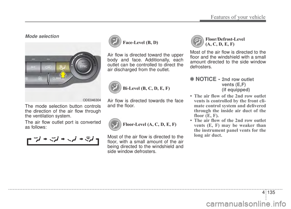
The mode selection button controls
the direction of the air flow through
the ventilation system.
The air flow outlet port is converted
as follows:Face-Level (B, D)
Air flow is directed toward the upper
body and face. Additionally, each
outlet can be controlled to direct the
air discharged from the outlet.
Bi-Level (B, C, D, E, F)
Air flow is directed towards the face
and the floor.
Floor-Level (A, C, D, E, F)
Most of the air flow is directed to the
floor, with a small amount of the air
being directed to the windshield and
side window defrosters. Floor/Defrost-Level
(A, C, D, E, F)
Most of the air flow is directed to the
floor and the windshield with a small
amount directed to the side window
defrosters.
✽ ✽ NOTICE - 2nd row outlet
vents (E,F)
(if equipped)
• The air flow of the 2nd row outlet
vents is controlled by the front cli-
mate control system and delivered
through the inside air duct of the
floor (E, F).
• The air flow of the 2nd row outlet vents (E, F) may be weaker than
the instrument panel vents for the
long air duct.ODE046304
Page 273 of 687
Features of your vehicle
136
4
Defrost-Level (A, D)
Most of the air flow is directed to the
windshield with a small amount of air
directed to the side window defrosters. Instrument panel vents
The outlet vents can be opened or
closed separately using the thumb-
wheel (if equipped).
Also, you can adjust the direction of
air delivery from these vents using
the vent control lever as shown.
Temperature control
The temperature will increase to the
maximum (HI) by turning the knob to
the extreme right.
The temperature will decrease to the
minimum (Lo) by turning the knob to
the extreme left.
When turning the knob, the tempera-
ture will increase or decrease by
1°F/0.5°C. When set to the lowest
temperature setting, the air condi-
tioning will operate continuously.
ODEP049319
■Driver’s side■Passenger’s side
ODE046305
ODEP049303
Page 399 of 687

589
Driving your vehicle
LKA system operation
To activate/deactivate LKA system:
With the ignition switch or ENGINE
START/STOP button in the ON posi-
tion, press the LKA system button
located on the instrument panel on
the lower left hand side of the driver.
The indicator ( )in the cluster dis-
play will initially illuminate white.
When the indicator(white) was acti-
vated in the previous ignition cycle,
the system turns on without any con-
trol. If you press the LKA system but-
ton again, the indicator on the cluster
display will go off.The color of indicator will change
depend on the condition of LKA sys-
tem.
- White : Sensor does not detect the lane marker or vehicle
speed is less than 40 mph
(60 km/h).
- Green : Sensor detects the lane marker and system is
able to control the steer-
ing.
System setting
The driver can change LKA to Lane
Departure Warning (LDW) or change
the LKA mode from the LCD display.
“User Settings → Driver Assistance →
Lane Safety → Lane Keeping
Assist/Lane Departure Warning/Off ”
Lane Keeping Assist
LKA mode guides the driver to keep
the vehicle within the lanes. It rarely
controls the steering wheel, when
the vehicle drives well inside the
lanes. However, it starts to control
the steering wheel, when the vehicle
is about to deviate from the lanes.
ODEP059113
Page 453 of 687

5143
Driving your vehicle
LFA system operation
To use Lane Following Assist two
steps are necessary:
(1) LFA system has to be enabled,and
(2) SCC system has to be activated
With the ignition switch or ENGINE
START/STOP button in the [ON],
select or release the setting from
“User setting → Driver Assistance →
Driving Assist →Lane Following
Assist”.
Select LFA system in the user setting
of the instrument panel.
The LFA system status is remem-
bered by the system and therefore
does not need to be enabled again
for each new journey.
(Continued)
- Depending on your surround- ings and road conditions, LFAsystem could fail to recognizethe lane and stop working. Inturn, extra caution is requiredwhile driving with LFA systemon.
- Be sure to check the non- operating conditions and cau-tions for the driver beforeusing LFA system.
- Do not place reflective materi- als such as white paper ormirror on the crash pad.Sunlight reflections can causea malfunction in LFA system.
- Too big sound from the sound system can interrupt thealarming sound from LFA sys-tem.
(Continued)(Continued)- Keeping your hands off the wheel while driving will triggerthe hands-off warning anddeactivate the steering-assistsystem. Put your hands backon the wheel, then the steer-ing-assist system will be re-activated.
- When driving at a high speed, the steering assist force canbecome weak and the vehiclecan drive out of its lane. Extracaution is required, and com-ply with the speed limit.
- Attaching an object to the steering wheel could detersteering assistance.
- Attaching an object to the steering wheel could deter thehands-off alarming system.
Page 454 of 687
Driving your vehicle
144
5
1. Press the CRUISE button, to turn
the system on. The CRUISE indi-
cator in the instrument cluster will
illuminate.
2. Accelerate to the desired speed. The smart cruise control speedcan be set as follows:
km/h): when there is no vehicle
in front
km/h): when there is a vehicle in
front 3. Move the switch down (to SET-),
and release it at the desired
speed. The set speed and vehicle
to vehicle distance on the LCD
screen will illuminate.
4. Release the accelerator pedal. The desired speed will automati-
cally be maintained. Once the system starts working, the
indicator light ( ) comes on the
instrument panel.
The indicator light colors according
to the system status are as follows.
Green: Active
White: Standby
For more SCC settings and details
refer to “Smart Cruise Control
(SCC)” in this chapter.
ODE056025ODE056024