Page 203 of 568
Features of your vehicle
118
4
MAX A/C selection
The MAX A/C mode is used to cool
the inside of the vehicle faster.
Air flow is directed toward the upper
body and face.
In this mode, the air conditioning and
the recirculated air position will be
selected automatically.
Instrument panel vents- Type A
The outlet vents can be opened or
closed separately using the thumb-
wheel. To close the vent, rotate it
downward to the maximum position.
Also, you can adjust the direction of
air delivery from these vents using
the vent control lever as shown.
- Type B
The outlet vents can be opened or
closed separately turning the knob
right or left. Also, you can adjust the
direction of air delivery from these
vents by moving the knob in any
direction.
OJF045077
OBD048305
OBD048308
OBD048309
■Type B
■Type A
Page 212 of 568

4127
Features of your vehicle
✽ ✽NOTICE
Never place anything over the sensor
located on the instrument panel to
ensure better control of the heating
and cooling system.
Manual heating and air condi-
tioning
The heating and cooling system can
be controlled manually by pressing
buttons or turning knob(s) other than
the AUTO button. In this case, the
system works sequentially according
to the order of buttons or knob(s)
selected.
1. Start the engine.
2. Set the mode to the desired posi-
tion.
For improving the effectiveness of
heating and cooling;- Heating:
- Cooling:
3. Set the temperature control to the desired position.
4. Set the air intake control to the outside (fresh) air position.
5. Set the fan speed control to the desired speed.
6. If air conditioning is desired, turn the air conditioning system on.
Press the AUTO button in order to
convert to full automatic control of
the system.
Mode selection
The mode selection button controls
the direction of the air flow through
the ventilation system.
The air flow outlet port is converted
as follows:
Refer to the illustration in the
“Manual climate control system”.
OBD048314
OBD048014
Page 214 of 568

4129
Features of your vehicle
Instrument panel vents- Type A
The outlet port can be opened or
closed separately using the horizon-
tal thumbwheel. To close the vent,
rotate it downward to the maximum
position. To open the vent, rotate it
upward to the desired position.
Also, you can adjust the direction of
air delivered from these vents using
the vent control lever as shown.
- Type B
The outlet vents can be opened or
closed separately turning the knob
right or left. Also, you can adjust the
direction of air delivery from these
vents by moving the knob in any
direction.
Temperature control
The temperature will increase to the
maximum (HI) by turning the knob all
the way to the right.
The temperature will decrease to the
minimum (Lo) by turning the knob all
the way to the left.
When turning the knob, the tempera-
ture will increase or decrease by
0.5°C/1°F. When set to the lowest
temperature increments setting, the
air conditioning will operate continu-
ously.
■Driver’s side■Passenger’s side
OBD048333
OBD048305
OBD048308
OBD048309
■Type B
■Type A
Page 305 of 568

559
Driving your vehicle
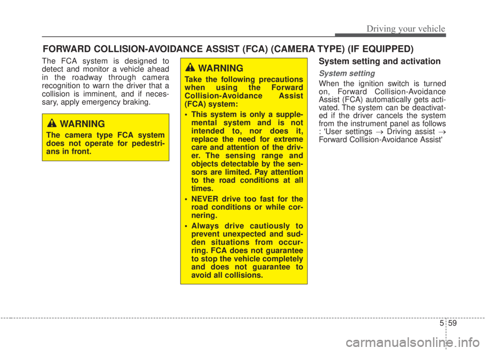
The FCA system is designed to
detect and monitor a vehicle ahead
in the roadway through camera
recognition to warn the driver that a
collision is imminent, and if neces-
sary, apply emergency braking.System setting and activation
System setting
When the ignition switch is turned
on, Forward Collision-Avoidance
Assist (FCA) automatically gets acti-
vated. The system can be deactivat-
ed if the driver cancels the system
from the instrument panel as follows
: 'User settings →Driving assist →
Forward Collision-Avoidance Assist'
FORWARD COLLISION-AVOIDANCE ASSIST (FCA) (CAMERA TYPE) (IF EQUIPPED)
WARNING
Take the following precautions
when using the Forward
Collision-Avoidance Assist
(FCA) system:
This system is only a supple-
mental system and is not
intended to, nor does it,
replace the need for extreme
care and attention of the driv-
er. The sensing range and
objects detectable by the sen-
sors are limited. Pay attention
to the road conditions at all
times.
NEVER drive too fast for the road conditions or while cor-
nering.
Always drive cautiously to prevent unexpected and sud-
den situations from occur-
ring. FCA does not guarantee
to stop the vehicle completely
and does not guarantee to
avoid all collisions.
WARNING
The camera type FCA system
does not operate for pedestri-
ans in front.
Page 318 of 568

Driving your vehicle
72
5
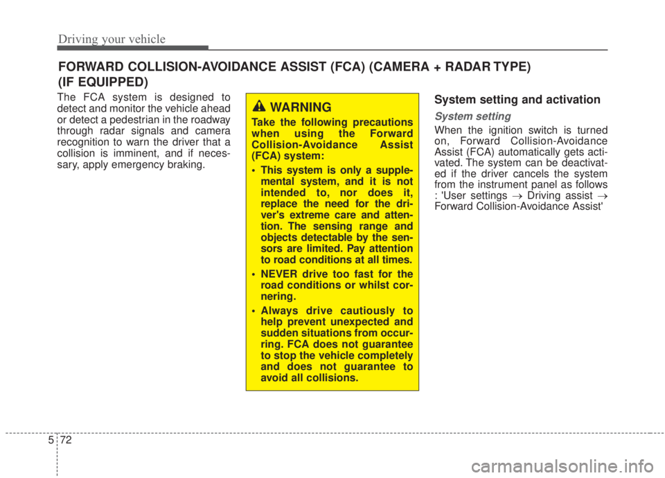
The FCA system is designed to
detect and monitor the vehicle ahead
or detect a pedestrian in the roadway
through radar signals and camera
recognition to warn the driver that a
collision is imminent, and if neces-
sary, apply emergency braking.System setting and activation
System setting
When the ignition switch is turned
on, Forward Collision-Avoidance
Assist (FCA) automatically gets acti-
vated. The system can be deactivat-
ed if the driver cancels the system
from the instrument panel as follows
: 'User settings → Driving assist →
Forward Collision-Avoidance Assist'
FORWARD COLLISION-AVOIDANCE ASSIST (FCA) (CAMERA + RADAR TYPE)
(IF EQUIPPED)
WARNING
Take the following precautions
when using the Forward
Collision-Avoidance Assist
(FCA) system:
This system is only a supple-
mental system, and it is not
intended to, nor does it,
replace the need for the dri-
ver's extreme care and atten-
tion. The sensing range and
objects detectable by the sen-
sors are limited. Pay attention
to road conditions at all times.
NEVER drive too fast for the road conditions or whilst cor-
nering.
Always drive cautiously to help prevent unexpected and
sudden situations from occur-
ring. FCA does not guarantee
to stop the vehicle completely
and does not guarantee to
avoid all collisions.
Page 372 of 568

Driving your vehicle
126
5
(Continued)
• When you replace the windshield
glass, front view camera or sys-
tem, take your vehicle to an
authorized Kia dealer and have
the system check to see if you need
a calibration.
• The system is designed to detect lane markers using a front view
camera. If the lane markers are
hard to detect, then the system
may be limited. Always be cau-
tious when using the system.
• When the lane markers are hard to detect, please refer to the
“Driver’s Attention” section in
this Chapter
• Do not remove or damage the related parts of LKA.
• Do not place objects on the dash- board that reflect light such as
mirrors, white paper, etc. This
may prevent the system from
functioning. (Continued)(Continued)
• If the audio sound is excessive, you
may not hear the warning sound
of the LKA.
• If you continue to drive with your hands off the steering wheel, the
LKA system will stop controlling
the steering wheel after the hands
off alarm. Afterwards, if you drive
with your hands on the steering
wheel, the control will be activated
again.
• At high vehicle speeds, the steer- ing torque of LKA may not be
enough to keep your vehicle with-
in the lane. If so, the vehicle may
move out of its lane. Therefore,
obey any applicable speed limits
when using LKA.
• If you attach objects to the steer- ing wheel, the system may not
assist steering.
• If you attach objects to the steer- ing wheel, the hands off alarm
may not work properly.LKA operation
To activate/deactivate the LKA:
With the ignition switch in the ON
position, press the LKA button locat-
ed on the instrument panel on the
lower left hand side of the driver.
The indicator in the cluster display
will initially illuminate white.
When the indicator(white) activated
in the previous ignition cycle, the
system turns on without any control.
If you press the LKA button again,
the indicator on the cluster display
will go off.
OBD058035
Page 505 of 568

Maintenance
68
7
Fuse NameFuse ratingCircuit Protected
MEMORY 110ADriver IMS (Integrated memory system) Module,Air Conditioner Control Module, Instrument Cluster
MODULE 110AKey Interlock Switch,Data Link Connector, Hazard Switch, Driver/Passenger Smart Key Outside Handle,
ICM (Integrated Circuit Module) Relay Box (Outside Mirror Folding/Unfolding Relay), Mood_LP_Unit
TRUNK10ATrunk Relay
POWER
WINDOW RH25APower Window Right Handle side Relay
POWER
WINDOW LH25APower Window Left Handle side Relay, Driver Safety Power Window Module
POWER SEAT DRIVER25ADriver Seat Manual Switch
MODULE 47.5ALane Keeping Assist Unit, IBU (Integrated Body Control Unit), Forward Collision Avoidance Assist Unit,
Blind-Spot Collision Warning Unit Left Handle side/Right Handle side
SEAT HEATER REAR15ARear Seat Warmer Control Module
HEATED MIRROR10ADriver/Passenger Power Outside Mirror, Air Conditioner Control Module, ECM (Engine Control
Module)/PCM (Power train Control Module)
SEAT HEATERFRONT20AFront Seat Warmer Control Module, Front Air Ventilation Seat Control Module
AMP25AAMP (Amplifier)
MULTI MEDIA15AAudio/Video & Navigation Head Unit
Instrument panel (Driver’s side fuse panel)
Page 509 of 568
Maintenance
72
7
Engine room compartment fuse panel
Fuse Name Fuse ratingCircuit Protected
MULTI
FUSE-1ALTERNATOR
200A
(NU 2.0L AKS) 150A
(GAMMA 1.6L T-GDI)
Fuse : BURGLAR ALARM, ABS1, ABS2, POWER OUTLET1, Alternator
MDPS80AMDPS (Motor Driven Power Steering) Unit
MULTI
FUSE-2
B+560AFuse : ECU 3, ECU 4, HORN, WIPER, A/C, Engine Control Relay
B+260AInstrument Panel Junction Block
B+360AInstrument Panel Junction Block
B+450AInstrument Panel Junction Block (Fuse : POWER WINDOW LH, POWER WINDOW RH,
TRUNK, SUNROOF 1, SEAT HEATER FRONT, AMP, POWER SEAT DRIVER)
COOLING FAN 160A[GAMMA 1.6L T-GDI] Cooling Fan 1 Relay
REAR HEATED40ARear Heated Relay
BLOWER40ABLOWER Relay
IG140AIgnition Switch, PDM #2 (ACC) Relay, PDM #3 (IG1) Relay
IG240AIgnition Switch, PDM #4 (IG2) Relay, START Relay
MULTI
FUSE-3PTC HEATER50APTC Heater Relay