2020 JEEP WRANGLER lock
[x] Cancel search: lockPage 26 of 276

To return the seat to a sitting position, rotate
the seatback upright until it locks and push
the seat rearward until the track locks.
NOTE:
• The front passenger seats have a track
memory, which returns the seat to just past
the halfway point of the track regardless of
its original position.
• The recliner and easy entry levers should
not be used during the automatic returning
of the seat to its sitting position.
Tip ‘n Slide Seats — Two Door Models
This feature allows the front seats to be
rotated toward the instrument panel to allow
easier entry into the rear seats.
Driver's Seat
Pull upward on the recline lever and bring the
seatback to its full forward position.
Rotate the entire seat assembly toward the
instrument panel.
Passenger Seat
In addition to Easy Entry, the front passenger
seat is also equipped with Tip ‘n Slide. This
feature allows for easier entry for rear passen-
gers.
Pull upward on the recline lever and slide the
entire seat forward (Easy Entry).
With the seat forward, pull the entire seat
assembly toward the instrument panel.
Removing The Rear Seat — Two Door
Models
NOTE:
• Prior to folding the rear seat, it may be
necessary to reposition the front seats.
• Be sure that the front seats are fully upright
and positioned forward. This will allow the
rear seat to fold down easily.
1. Lift the seatback release lever and fold
the seatback forward.2. Slowly flip the entire seat forward.
WARNING!
Do not drive the vehicle with the seat in
the forward tumble position. The seat
must be latched to all floor attachments
when the vehicle is in motion.
Seatback Release Lever
GETTING TO KNOW YOUR VEHICLE
24
Page 28 of 276

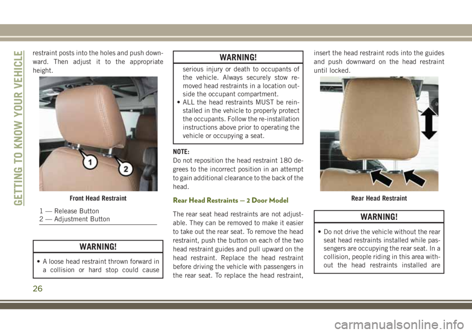
restraint posts into the holes and push down-
ward. Then adjust it to the appropriate
height.
WARNING!
• A loose head restraint thrown forward in
a collision or hard stop could cause
WARNING!
serious injury or death to occupants of
the vehicle. Always securely stow re-
moved head restraints in a location out-
side the occupant compartment.
• ALL the head restraints MUST be rein-
stalled in the vehicle to properly protect
the occupants. Follow the re-installation
instructions above prior to operating the
vehicle or occupying a seat.
NOTE:
Do not reposition the head restraint 180 de-
grees to the incorrect position in an attempt
to gain additional clearance to the back of the
head.
Rear Head Restraints — 2 Door Model
The rear seat head restraints are not adjust-
able. They can be removed to make it easier
to take out the rear seat. To remove the head
restraint, push the button on each of the two
head restraint guides and pull upward on the
head restraint. Replace the head restraint
before driving the vehicle with passengers in
the rear seat. To replace the head restraint,insert the head restraint rods into the guides
and push downward on the head restraint
until locked.WARNING!
• Do not drive the vehicle without the rear
seat head restraints installed while pas-
sengers are occupying the rear seat. In a
collision, people riding in this area with-
out the head restraints installed are
Front Head Restraint
1 — Release Button
2 — Adjustment Button
Rear Head RestraintGETTING TO KNOW YOUR VEHICLE
26
Page 30 of 276

STEERING WHEEL
Tilt Steering Column
This feature allows you to tilt the steering
column upward or downward. The tilt lever is
located on the steering column, below the
turn signal lever.
To Adjust The Tilt Steering Column
1. Push down on the lever to unlock the
steering column.2. With one hand firmly on the steering
wheel, move the steering column up or
down, as desired.
3. Pull upwards on the lever to lock the
column firmly in place.
WARNING!
Do not adjust the steering column while
driving. Adjusting the steering column
while driving or driving with the steering
column unlocked, could cause the driver
to lose control of the vehicle. Failure to
follow this warning may result in serious
injury or death.
MIRRORS
Heated Mirrors — If Equipped
These mirrors are heated to melt frost or ice.
This feature will be activated whenever you
turn on the rear window defroster (if
equipped). Refer to “Climate Controls” in
“Getting To Know Your Vehicle” for further
information.
EXTERIOR LIGHTS
Headlights And Parking Lights
Turn the end of the multifunction lever to the
first detent for parking light operation. Turn
to the second detent for headlight operation.
Tilt Steering Column Lever
Turn Signal/Lights Lever
1 — Pull Front Fog Light
2 — Rotate Headlight Switch
3 — Rotate Instrument Panel Dimmer
GETTING TO KNOW YOUR VEHICLE
28
Page 31 of 276

Daytime Running Lights — If Equipped
The headlights come on at a low intensity level
when shifted into any position other than PARK
(auto transmission) or when the vehicle begins
to move (manual transmission).
NOTE:
The Daytime Running Light, on the same side
of the vehicle as the active turn signal, will
turn off automatically when a turn signal is in
operation and turn on again when the turn
signal is not operating.
High/Low Beam Switch
Push the multifunction lever toward the in-
strument panel to switch the headlights to
high beams. Pulling the multifunction lever
back toward the steering wheel will return the
lights to low beams.
Flash-To-Pass
You can signal another vehicle with your
headlights by lightly pulling the multifunc-
tion lever toward you. This will cause the high
beam headlights to turn on, and remain on,
until the lever is released.
Automatic Headlights — If Equipped
This system automatically turns the head-
lights on or off according to ambient light
levels. To turn the system on, turn the end of
the multifunction lever to the AUTO position
(third detent). When the system is on, the
Headlight Time Delay feature is also on. This
means the headlights will stay on for up to
90 seconds after you turn the ignition switch
to the LOCK position. To turn the Automatic
System off, turn the end of the multifunction
lever out of the AUTO position.
NOTE:
The engine must be running before the head-
lights will turn on in the Automatic mode.
Front Fog Lights
The front fog light switch is located on the
multifunction lever. To activate the front fog
lights, turn on the parking or low beam head-
lights and pull out the end of the lever.NOTE:
The fog lights will only operate with the park-
ing lights or the headlights on low beam.
Selecting high beam headlights will turn off
the fog lights.
Rear Fog Lights — If Equipped
The rear fog lights may be operated, as de-
sired, when visibility is poor due to fog. To
activate the rear fog lights, turn on the low
beam, high beam, or front fog lamps, pull out
the end of the multifunction lever and rotate
the lever to the last detent.
Turn Signals
Move the multifunction lever up or down and
the arrows on each side of the instrument
cluster flash to show proper operation of the
front and rear turn signal lights.
29
Page 34 of 276

Rear Window Wiper/Washer — If
Equipped
A rotary switch on the center portion of the
control lever (located on the right side of the
steering column) controls the operation of
the rear wiper/washer function.
Rotate the switch upward to the first detent
position for rear wiper operation.
Rotate the switch upward past the first detent
to activate the rear washer. The washer pump
and the wiper will continue to operate as long
as the switch is held. Upon release, the wiper
will cycle two to three times before returning
to the set position.
If the rear wiper is operating when the igni-
tion is turned to the LOCK position, the wiper
will automatically return to the “park” posi-
tion. When the vehicle is restarted, the wiper
will resume function at whichever position
the switch is set at.
GETTING TO KNOW YOUR VEHICLE
32
Page 37 of 276

Icon Description
Temperature Control
Use this control to regulate the temperature of the air inside the passenger compartment. Rotating the knob counter-
clockwise, from top center into the blue area of the scale, indicates cooler temperatures. Rotating the knob clockwise,
into the red area, indicates warmer temperatures.
Blower Control
There are seven blower speeds. Use this control to regulate the amount of air forced through the system in any mode
you select. The blower speed increases as you move the control clockwise from the off position.
NOTE:
Depending on the configuration, your vehicle may be equipped with four blower speeds.
Modes Control
Turn the knob to adjust airflow distribution. The airflow distribution mode can be adjusted so air comes from the instru-
ment panel outlets, floor outlets, defrost outlets and demist outlets. The Mode settings are as follows:
Panel Mode
Panel Mode
Air comes from the outlets in the instrument panel. Each of these outlets can be individually adjusted to direct the flow
of air. The air vanes of the center outlets and outboard outlets can be moved up and down or side to side to regulate
airflow direction.
Bi-Level Mode
Bi-Level Mode
Air comes from the instrument panel outlets and floor outlets. A slight amount of air is directed through the defrost and
side window demister outlets.
NOTE:
Bi-Level mode is designed under comfort conditions to provide cooler air out of the panel outlets and warmer air from
the floor outlets.
35
Page 41 of 276

NOTE:
• For vehicles not equipped with the instru-
ment cluster display, the power window
switches will remain active for 45 seconds
after the ignition switch is turned to the
LOCK position. Opening either front door
will cancel this feature.
• For vehicles equipped with the instrument
cluster display, the power window switches
will remain active for up to 10 minutes after
the ignition switch is turned to the LOCK
position. Opening either front door will can-
cel this feature.
Four-Door Models
The lower left switch controls the left rear
passenger window, and the lower right switch
controls the right rear passenger window.
Wind Buffeting
Wind buffeting can be described as the per-
ception of pressure on the ears or a
helicopter-type sound in the ears. Your ve-
hicle may exhibit wind buffeting with thewindows down in certain open or partially
open positions. This is a normal occurrence
and can be minimized by adjusting the win-
dow opening.
REMOVABLE TOP
INFORMATION
Please visit http://www.jeep.com/en/wrangler-
rooftop-instructions/ for instructional videos.
For complete information, refer to your Owner's
Manual.
Sunrider And Soft Top
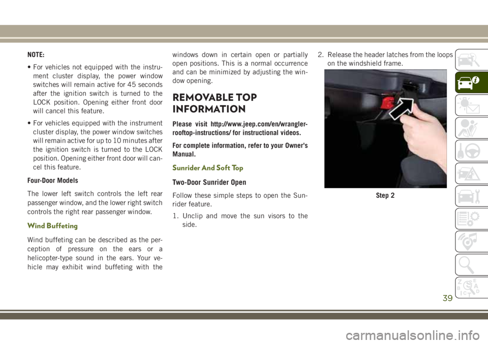
Two-Door Sunrider Open
Follow these simple steps to open the Sun-
rider feature.
1. Unclip and move the sun visors to the
side.2. Release the header latches from the loops
on the windshield frame.Step 2
39
Page 42 of 276

3. Make sure to slide the plastic sleeves
forward to unlock the Sunrider links.4. Grasp the header and lift the top back.
Make sure the material is folded back as
shown.5. Locate the straps to secure the side bows.
Wrap the straps around the bows as
shown. Repeat on the other side.
6. Reposition the sun visors.
NOTE:
If you are going to be driving faster than
40 mph (64 km/h) with the Sunrider feature
open, it is recommended that you remove the
rear window of the vehicle.
•To close the Sunrider feature, perform the
above steps in the opposite order.
Step 3
Step 4Step 5GETTING TO KNOW YOUR VEHICLE
40