2020 JEEP COMPASS wheel
[x] Cancel search: wheelPage 181 of 328

179
High Intensity Discharge (HID)
Headlamps — If Equipped
The headlamps contain a type of high voltage
discharge light source. High voltage can
remain in the circuit even with the headlamp
switch off. Because of this, you should not
attempt to service a HID headlamp light
source yourself. If an HID headlamp light
source fails, take your vehicle to an autho-
rized dealer for service.
NOTE:
On vehicles equipped with HID headlamps,
when the headlamps are turned on, there is
a blue hue to the lights. This diminishes and
becomes more white after approximately 10
seconds, as the system charges.
Replacing Exterior Bulbs
Headlamps
Hi/Lo Beam Light Halogen
The bulbs can be accessed from the wheel
liner with the following procedure:
1. Turn the front wheels completely.
2. Remove the wheel liner.
3. Remove the headlamp bulb cap.
Headlamp
4. Rotate the headlamp bulb socket coun -
terclockwise then pull outwards. Headlamp Bulb Socket
5. Push on the locking tab on the headlamp bulb connector and remove the bulb and
socket.
6. Install the new headlamp bulb making sure it’s properly locked.
7. Install the headlamp bulb and socket; turn it clockwise making sure it is prop -
erly locked.
8. Reinstall the wheel liner.
NOTE:
We advise referring to an authorized dealer.
WARNING!
A transient high voltage occurs at the bulb
sockets of HID headlamps when the
headlamp switch is turned ON. It may
cause serious electrical shock or
electrocution if not serviced properly. See
an authorized dealer for service.
1 — Low Beam Bulb Cap
2 — High Beam Bulb Cap
WARNING!
Carry out the operation of replacing lamps
only with the engine off. Also make sure
that the engine is cold, to avoid the danger
of burns.
2020_JEEP_M6_UG_UK.book Page 179
Page 182 of 328

IN CASE OF EMERGENCY
180
Turn Signal Light/Position Lights/Daytime
Running Lights
To replace the bulbs proceed as follows:
1. Turn the front wheels completely.
2. Remove the wheel liner.
3. Remove the electrical connectors.
4. For the DRL bulb, grip the bulb at the topand bottom locking tabs and squeeze to
remove the bulb.
5. To replace the DRL bulb gently push bulb towards housing. Be sure to hear both the
top and bottom locking tabs “CLICK” to
ensure the bulb is properly seated.
6. For the turn signal bulb, rotate in a coun -
terclockwise direction and remove the
bulb and bulb socket. Pull the bulb
axially to remove it from the socket.
7. Install the bulb and sockets and rotate them clockwise making sure that it is
properly locked.
8. Reconnect the electrical connectors.
9. Reinstall the wheel liner.
NOTE:
We advise referring to an authorized dealer. Front Fog Lights
To replace the bulbs proceed as follows:
1. Turn the front wheels completely.
2. Remove the wheel liner.
3. By pushing the electrical connector tab
remove the electrical connector.
4. Rotate the bulb counterclockwise, and then replace the bulb.
Fog Lamp Housing
5. Insert the new bulb in the socket, making sure the bulb is locked into place.
6. Reconnect the electrical connector. 7. Reinstall the wheel liner.
NOTE:
We advise referring to an authorized dealer.
Rear Body Side Tail Lamps
Contain the following:
Position lights
Stop lights
Direction indicator
To replace the bulbs proceed as follows:
1. Open the liftgate.
2. Using a suitable tool remove fasteners.
Body Side Tail Lamp Opening
1 — Bulb
1 — Fasteners
2020_JEEP_M6_UG_UK.book Page 180
Page 186 of 328

IN CASE OF EMERGENCY
184
F18– –20 Amp Yellow 12 Volt Rear Cargo Outlet Ignition Powered
F19 – –7.5 Amp Brown Air Conditioner Compressor
F20 – –20 Amp Yellow Cigar Lighter
F21 – –20 Amp Yellow Fuel Pump (*)
F22 – –20 Amp Yellow –
Gas Engine
15 Amp Blue – Diesel Engine Gas - Ign Coil/Fuel Injector Diesel- Diesel
Components (*)
F23 – –30 Amp Green Window Heater Grid
F24 – –15 Amp Blue Electronic Unit Supply Automatic
Transmission (*)
F30 – –20 Amp Yellow
(Customer Selectable, Move From F18) 12 Volt Rear Cargo Outlet Constant Battery
Powered
F81 50 Amp Red
60 Amp Blue –
–Smart Driver Unit DDCT – 1.4L Glow Plug
Module, DDCT SDU Battery Feed (*)
F82 –40 Amp Green –Diesel Fuel Filter Heater (*)
F83 –40 Amp Green –HVAC Fan
F84 – –30 Amp Green Power Supply All Wheel Drive (*)
F87 – –5 Amp Tan Gear Selector Automatic Transmission (*)
F88 – –7.5 Amp Brown Heated Outside Mirrors
F89 – –30 Amp Green Heated Rear Window
F90 – –5 Amp Tan IBS Sensor (Battery State Of Charge) (*)
CavityMaxi Fuse Cartridge Fuse Mini Fuse Description
2020_JEEP_M6_UG_UK.book Page 184
Page 190 of 328

IN CASE OF EMERGENCY
188
On the Rear Cargo Fuse/Relay Distribution Unit bracket, there is a Maxi Fuse holder for the Power Liftgate and an ATO / UniVal fuse holder
for the HIFI Audio System.F6
7.5 Amp Brown Power Lumbar (Power Seats)
F7 15 Amp Blue Heated Steering Wheel / Ventilated Seats
F8 20 Amp Yellow Heated Seats
Fuse Holder No. 2
CavityMini Fuse Description
F110 Amp RedTTM IGN Feed
F5 15 Amp Blue Controller Exterior Lighting Lights (Drivers Side)
F6 15 Amp Blue Controller Exterior Lighting Lights (Passenger Side)
F7 10 Amp RedTTM Jumper Battery Feed (*)
Cavity Maxi Fuse Description
F0130 Amp Green Power Liftgate
CavityATO / UniVal Fuse Description
F0225 Amp Clear HIFI Audio System
Fuse Holder No. 1
CavityMini Fuse Description
2020_JEEP_M6_UG_UK.book Page 188
Page 191 of 328

189
JACKING AND TIRE
CHANGING Jack Location/Spare Tire Stowage
If equipped, the jack and tools are located in
the rear storage compartment, below the
spare tire.Jack And Tools Location
1. Open the liftgate.
2. Lift the access cover using the load floor handle. 3. Remove the fastener securing the spare
tire, and remove the spare wheel from the
vehicle. The jack and tools will be found
beneath.
Spare Tire Fastener
4. Remove the alignment pin from the middle, rotate the jack counterclockwise,
and lift it from the foam tray.
WARNING!
Do not attempt to change a tire on the
side of the vehicle close to moving
traffic. Pull far enough off the road to
avoid the danger of being hit when oper -
ating the jack or changing the wheel.
Being under a jacked-up vehicle is
dangerous. The vehicle could slip off the
jack and fall on you. You could be
crushed. Never put any part of your body
under a vehicle that is on a jack. If you
need to get under a raised vehicle, take
it to a service center where it can be
raised on a lift.
Never start or run the engine while the
vehicle is on a jack.
The jack is designed to be used as a tool
for changing tires only. The jack should
not be used to lift the vehicle for service
purposes. The vehicle should be jacked
on a firm level surface only. Avoid ice or
slippery areas.
1 — Jack
2 — Alignment Pin
3 — Wheel Bolt Wrench
4 — Emergency Funnel
5 — Screwdriver
2020_JEEP_M6_UG_UK.book Page 189
Page 192 of 328

IN CASE OF EMERGENCY
190(Continued)
5. Remove the jack and wheel bolt wrench.Jack And ToolsPreparations For Jacking
1. Park the vehicle on a firm level surface asfar from the edge of the roadway as
possible. Avoid icy or slippery areas.
2. Turn on the Hazard Warning flasher.
3. Apply the parking brake.
4. Place the gear selector into PARK (P) (automatic transmission) or REVERSE
(R) (manual transmission).
5. Place the ignition in the OFF position.
6. Block both the front and rear of the wheel diagonally opposite the jacking position.
For example, if the right front wheel is
being changed, block the left rear wheel. Wheel Blocked
NOTE:
Passengers should not remain in the vehicle
when the vehicle is being raised or lifted.
Jacking Instructions
1 — Wheel Bolt Wrench
2 — Jack
3 — Emergency Funnel
4 — Screwdriver
5 — Alignment Pin
WARNING!
A loose tire or jack thrown forward in a
collision or hard stop could endanger the
occupants of the vehicle. Always stow the
jack parts and the spare tire in the places
provided. Have the deflated (flat) tire
repaired or replaced immediately.
WARNING!
Do not attempt to change a tire on the side
of the vehicle close to moving traffic. Pull
far enough off the road to avoid being hit
when operating the jack or changing the
wheel.
WARNING!
Carefully follow these tire changing
warnings to help prevent personal injury or
damage to your vehicle:
Always park on a firm, level surface as
far from the edge of the roadway as
possible before raising the vehicle.
2020_JEEP_M6_UG_UK.book Page 190
Page 193 of 328

191(Continued)
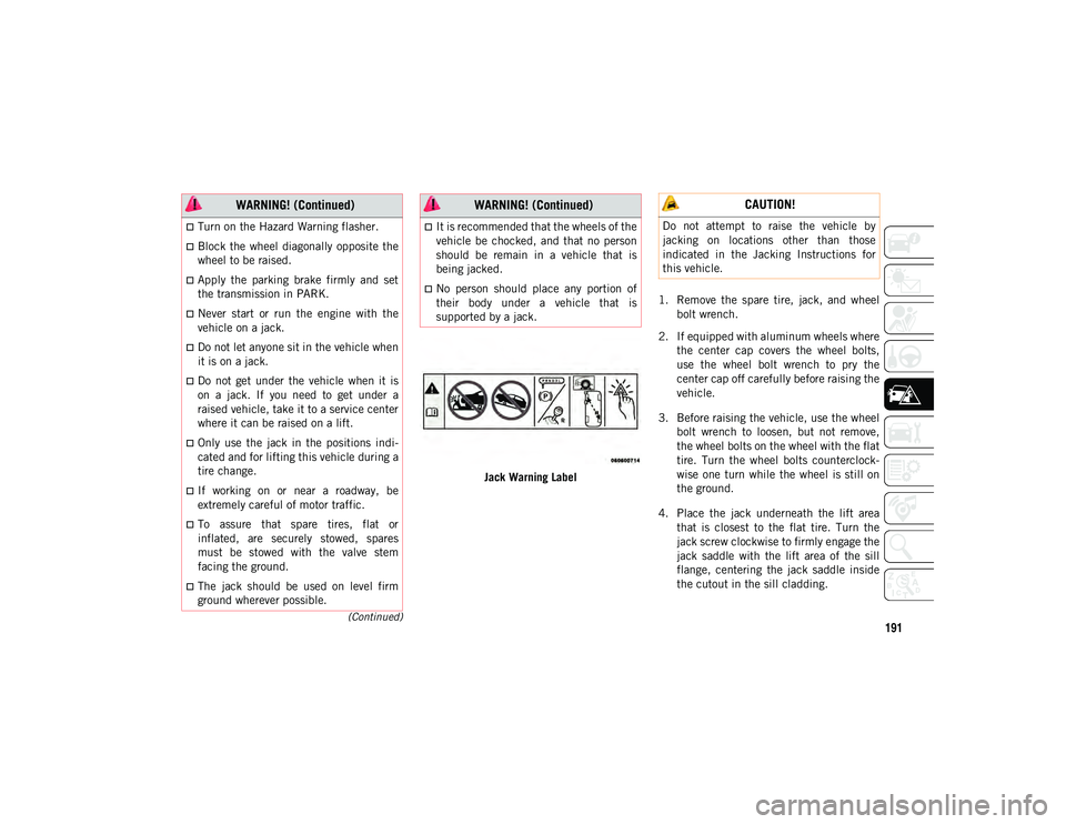
Jack Warning Label1. Remove the spare tire, jack, and wheel
bolt wrench.
2. If equipped with aluminum wheels where the center cap covers the wheel bolts,
use the wheel bolt wrench to pry the
center cap off carefully before raising the
vehicle.
3. Before raising the vehicle, use the wheel bolt wrench to loosen, but not remove,
the wheel bolts on the wheel with the flat
tire. Turn the wheel bolts counterclock -
wise one turn while the wheel is still on
the ground.
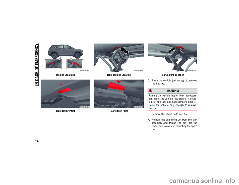
4. Place the jack underneath the lift area that is closest to the flat tire. Turn the
jack screw clockwise to firmly engage the
jack saddle with the lift area of the sill
flange, centering the jack saddle inside
the cutout in the sill cladding.
Turn on the Hazard Warning flasher.
Block the wheel diagonally opposite the
wheel to be raised.
Apply the parking brake firmly and set
the transmission in PARK.
Never start or run the engine with the
vehicle on a jack.
Do not let anyone sit in the vehicle when
it is on a jack.
Do not get under the vehicle when it is
on a jack. If you need to get under a
raised vehicle, take it to a service center
where it can be raised on a lift.
Only use the jack in the positions indi -
cated and for lifting this vehicle during a
tire change.
If working on or near a roadway, be
extremely careful of motor traffic.
To assure that spare tires, flat or
inflated, are securely stowed, spares
must be stowed with the valve stem
facing the ground.
The jack should be used on level firm
ground wherever possible.
WARNING! (Continued)
It is recommended that the wheels of the
vehicle be chocked, and that no person
should be remain in a vehicle that is
being jacked.
No person should place any portion of
their body under a vehicle that is
supported by a jack.
WARNING! (Continued) CAUTION!
Do not attempt to raise the vehicle by
jacking on locations other than those
indicated in the Jacking Instructions for
this vehicle.
2020_JEEP_M6_UG_UK.book Page 191
Page 194 of 328

IN CASE OF EMERGENCY
192
Jacking LocationsFront Lifting Point Front Jacking Location
Rear Lifting Point Rear Jacking Location
5. Raise the vehicle just enough to remove the flat tire.
6. Remove the wheel bolts and tire.
7. Remove the alignment pin from the jack assembly and thread the pin into the
wheel hub to assist in mounting the spare
tire.
WARNING!
Raising the vehicle higher than necessary
can make the vehicle less stable. It could
slip off the jack and hurt someone near it.
Raise the vehicle only enough to remove
the tire.
2020_JEEP_M6_UG_UK.book Page 192