2020 HYUNDAI TUCSON ULTIMATE engine oil
[x] Cancel search: engine oilPage 457 of 546
7-23
7
Maintenance
B BR
RA
AK
KE
E
F
FL
LU
UI
ID
D
Checking the Brake Fluid
Level
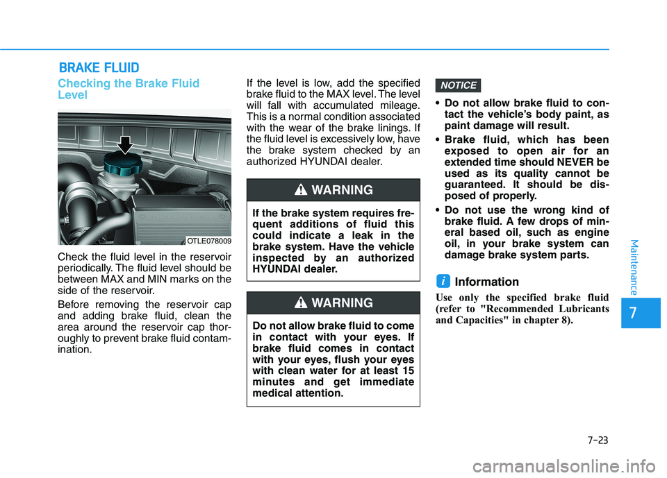
Check the fluid level in the reservoir
periodically. The fluid level should be
between MAX and MIN marks on the
side of the reservoir.
Before removing the reservoir cap
and adding brake fluid, clean the
area around the reservoir cap thor-
oughly to prevent brake fluid contam-
ination.If the level is low, add the specified
brake fluid to the MAX level. The level
will fall with accumulated mileage.
This is a normal condition associated
with the wear of the brake linings. If
the fluid level is excessively low, have
the brake system checked by an
authorized HYUNDAI dealer. Do not allow brake fluid to con-
tact the vehicle’s body paint, as
paint damage will result.
Brake fluid, which has been
exposed to open air for an
extended time should NEVER be
used as its quality cannot be
guaranteed. It should be dis-
posed of properly.
Do not use the wrong kind of
brake fluid. A few drops of min-
eral based oil, such as engine
oil, in your brake system can
damage brake system parts.
Information
Use only the specified brake fluid
(refer to "Recommended Lubricants
and Capacities" in chapter 8).
i
NOTICE
If the brake system requires fre-
quent additions of fluid this
could indicate a leak in the
brake system. Have the vehicle
inspected by an authorized
HYUNDAI dealer.
WARNING
Do not allow brake fluid to come
in contact with your eyes. If
brake fluid comes in contact
with your eyes, flush your eyes
with clean water for at least 15
minutes and get immediate
medical attention.
WARNING
OTLE078009
Page 485 of 546
7-51
7
Maintenance
F FU
US
SE
ES
S
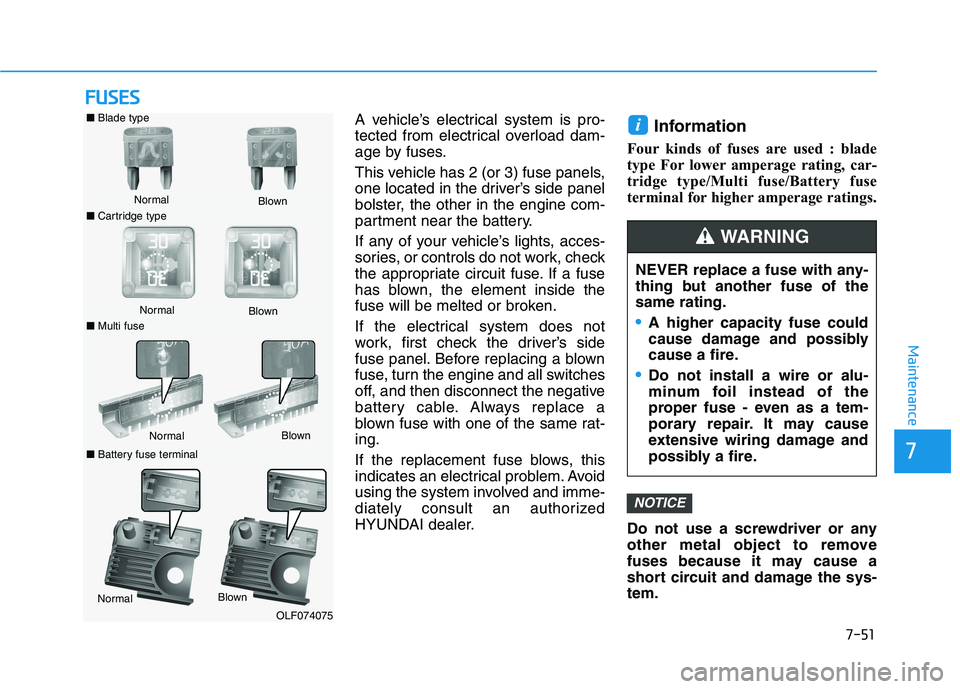
A vehicle’s electrical system is pro-
tected from electrical overload dam-
age by fuses.
This vehicle has 2 (or 3) fuse panels,
one located in the driver’s side panel
bolster, the other in the engine com-
partment near the battery.
If any of your vehicle’s lights, acces-
sories, or controls do not work, check
the appropriate circuit fuse. If a fuse
has blown, the element inside the
fuse will be melted or broken.
If the electrical system does not
work, first check the driver’s side
fuse panel. Before replacing a blown
fuse, turn the engine and all switches
off, and then disconnect the negative
battery cable. Always replace a
blown fuse with one of the same rat-
ing.
If the replacement fuse blows, this
indicates an electrical problem. Avoid
using the system involved and imme-
diately consult an authorized
HYUNDAI dealer.Information
Four kinds of fuses are used : blade
type For lower amperage rating, car-
tridge type/Multi fuse/Battery fuse
terminal for higher amperage ratings.
Do not use a screwdriver or any
other metal object to remove
fuses because it may cause a
short circuit and damage the sys-
tem.
NOTICE
i
NEVER replace a fuse with any-
thing but another fuse of the
same rating.
A higher capacity fuse could
cause damage and possibly
cause a fire.
Do not install a wire or alu-
minum foil instead of the
proper fuse - even as a tem-
porary repair. It may cause
extensive wiring damage and
possibly a fire.
WARNING
■Blade type
Normal
■Cartridge typeBlown
Normal
Blown
■Multi fuse
NormalBlown
■Battery fuse terminal
NormalBlown
OLF074075
Page 496 of 546
![HYUNDAI TUCSON ULTIMATE 2020 Owners Manual 7-62
Maintenance
Engine compartment main fuse panel
Fuse Name Fuse ratingCircuit Protected
WIPER FRT210A BCW
E-CVVT220A [G4KJ] PCM
E-CVVT120A [G4KJ] PCM
WIPER FRT125A Ignition Switch (W/O Smart Key), HYUNDAI TUCSON ULTIMATE 2020 Owners Manual 7-62
Maintenance
Engine compartment main fuse panel
Fuse Name Fuse ratingCircuit Protected
WIPER FRT210A BCW
E-CVVT220A [G4KJ] PCM
E-CVVT120A [G4KJ] PCM
WIPER FRT125A Ignition Switch (W/O Smart Key),](/manual-img/35/56196/w960_56196-495.png)
7-62
Maintenance
Engine compartment main fuse panel
Fuse Name Fuse ratingCircuit Protected
WIPER FRT210A BCW
E-CVVT220A [G4KJ] PCM
E-CVVT120A [G4KJ] PCM
WIPER FRT125A Ignition Switch (W/O Smart Key), PDM (IG2) Relay (With Smart Key)
TCU115A [G4FJ] TCM (7DCT), [G4KJ] PCM
A/C10A E/R Junction Block (A/C Relay)
ECU320A PCM (G4NC/G4KJ) / ECM (G4FJ)
HORN15A Horn Relay
BATTERY
MANAGEMENT10A Not Used
SENSOR210A
[G4NC] Oil Control Valve #1/#2, Camshaft Position Sensor #1/#2, Purge Control Solenoid Valve,
Variable Intake Solenoid Valve, Canister Close Valve, E/R Junction Block (A/C Relay,
Cooling Fan High Relay)
[G4FJ] Oil Control Valve #1/#2, Purge Control Solenoid Valve, Canister Close Valve,
RCV Control Solenoid Valve, E/R Junction Block (A/C Relay, Cooling Fan High Relay)
[G4KJ] Canister Close Valve, Variable Intake Solenoid Valve,
E/R Junction Block (A/C Relay, Cooling Fan High Relay)
SENSOR115A Oxygen Sensor (Up)/(Down)
ECU220A IGNITION COIL #1/#2/#3/#4, Condenser (G4NC)
ECU515A PCM (G4NC) / ECM (G4FJ)
ECU415A PCM (G4NC/G4KJ) / ECM (G4FJ)
SENSOR310A[G4NC] PCM
[G4FJ] ECM
[G4KJ] Purge Control Solenoid Valve, Oil Control Valve
Page 510 of 546

7-76
Maintenance
High-pressure washing
When using high-pressure wash-
ers, make sure to maintain suffi-
cient distance from the vehicle.
Insufficient clearance or excessive
pressure can lead to component
damage or water penetration.
Do not spray the camera, sensors
or its surrounding area directly with
a high pressure washer. Shock
applied from high pressure water
may cause the device to not oper-
ate normally.
Do not bring the nozzle tip close to
boots (rubber or plastic covers)or
connectors as they may be dam-
aged if they come into contact with
high pressure water.
Do not use any high-pressure noz-
zles, which induce either one-direct
water stream or water swirling. Water washing in the engine
compartment including high
pressure water washing may
cause the failure of electrical cir-
cuits located in the engine com-
partment.
Never allow water or other liq-
uids to come in contact with
electrical/electronic compo-
nents inside the vehicle as this
may damage them.Matte paint finish vehicle
(if equipped)
Automatic car wash which uses
rotating brushes should not be
used as this can damage the sur-
face of your vehicle. A steam
cleaner which washes the vehicle
surface at high temperature may
result the oil to adhere and leave
stains that is difficult to remove.
Use a soft cloth (e.g. microfiber
towel or sponge) when washing
your vehicle and dry with a
microfiber towel. When you hand
wash your vehicle, you should not
use a cleaner that finishes with
wax. If the vehicle surface is too
dirty (sand, dirt, dust, contami-
nant, etc.), clean the surface with
water before washing the car.
NOTICE
NOTICE
OTL078049
Page 529 of 546
Specifications, Consumer information and Reporting safety defects
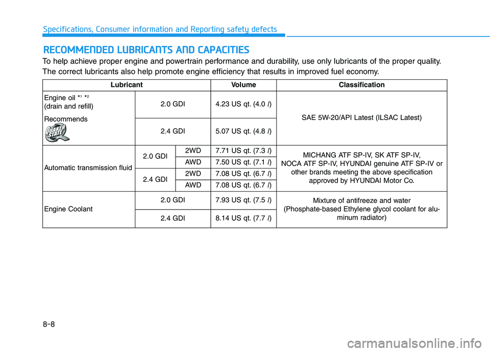
To help achieve proper engine and powertrain performance and durability, use only lubricants of the proper quality.
The correct lubricants also help promote engine efficiency that results in improved fuel economy.
R RE
EC
CO
OM
MM
ME
EN
ND
DE
ED
D
L
LU
UB
BR
RI
IC
CA
AN
NT
TS
S
A
AN
ND
D
C
CA
AP
PA
AC
CI
IT
TI
IE
ES
S
Lubricant Volume Classification
Engine oil *
1*2
(drain and refill)
Recommends2.0 GDI4.23 US qt. (4.0 l)
SAE 5W-20/API Latest (ILSAC Latest)
2.4 GDI5.07 US qt. (4.8 l)
Automatic transmission fluid2.0 GDI2WD7.71 US qt. (7.3 l)
MICHANG ATF SP-IV, SK ATF SP-IV,
NOCA ATF SP-IV, HYUNDAI genuine ATF SP-IV or
other brands meeting the above specification
approved by HYUNDAI Motor Co. AWD7.50 US qt. (7.1 l)
2.4 GDI2WD7.08 US qt. (6.7 l)
AWD7.08 US qt. (6.7 l)
Engine Coolant
2.0 GDI7.93 US qt. (7.5 l)Mixture of antifreeze and water
(Phosphate-based Ethylene glycol coolant for alu-
minum radiator)
2.4 GDI8.14 US qt. (7.7 l)
8-8
Page 530 of 546
8-9
88
Specifications, Consumer information and Reporting safety defects
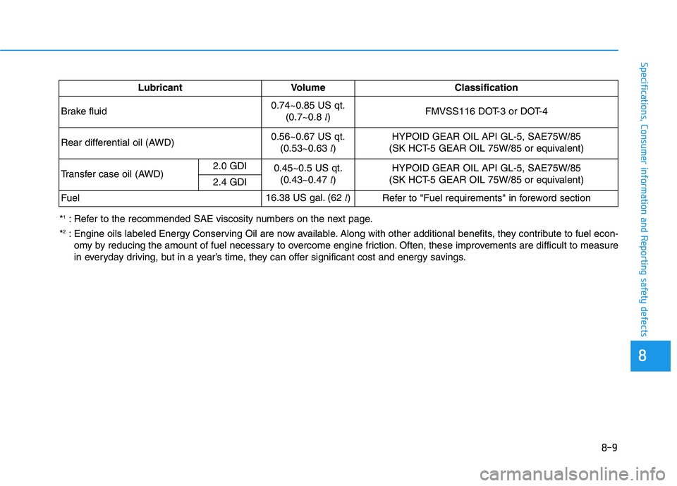
*1: Refer to the recommended SAE viscosity numbers on the next page.
*
2: Engine oils labeled Energy Conserving Oil are now available. Along with other additional benefits, they contribute to fuel econ-
omy by reducing the amount of fuel necessary to overcome engine friction. Often, these improvements are difficult to measure
in everyday driving, but in a year’s time, they can offer significant cost and energy savings.Lubricant Volume Classification
Brake fluid0.74~0.85 US qt.
(0.7~0.8 l)FMVSS116 DOT-3 or DOT-4
Rear differential oil (AWD)0.56~0.67 US qt.
(0.53~0.63 l)HYPOID GEAR OIL API GL-5, SAE75W/85
(SK HCT-5 GEAR OIL 75W/85 or equivalent)
Transfer case oil (AWD)2.0 GDI
0.45~0.5 US qt.
(0.43~0.47 l)HYPOID GEAR OIL API GL-5, SAE75W/85
(SK HCT-5 GEAR OIL 75W/85 or equivalent)
2.4 GDI
Fuel16.38 US gal. (62 l)
Refer to "Fuel requirements" in foreword section
Page 531 of 546
8-10
Specifications, Consumer information and Reporting safety defects
Recommended SAE Viscosity
Number
Always be sure to clean the area
around any filler plug, drain
plug, or dipstick before check-
ing or draining any lubricant.
This is especially important in
dusty or sandy areas and when
the vehicle is used on unpaved
roads. Cleaning the plug and
dipstick areas will prevent dirt
and grit from entering the
engine and other mechanisms
that could be damaged.
CAUTION
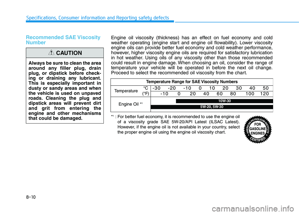
Engine oil viscosity (thickness) has an effect on fuel economy and cold
weather operating (engine start and engine oil flowability). Lower viscosity
engine oils can provide better fuel economy and cold weather performance,
however, higher viscosity engine oils are required for satisfactory lubrication
in hot weather. Using oils of any viscosity other than those recommended
could result in engine damage. When choosing an oil, consider the range of
temperature your vehicle will be operated in before the next oil change.
Proceed to select the recommended oil viscosity from the chart.
Temperature Range for SAE Viscosity Numbers
Temperature -30 -20 -10 0 10 20 30 40 50
-10 0 20 40 60 80 100 120
Engine Oil *110W-30
5W-20, 5W-30
°C
(°F)
*1: For better fuel economy, it is recommended to use the engine oil
of a viscosity grade SAE 5W-20/API Latest (ILSAC Latest).
However, if the engine oil is not available in your country, select
the proper engine oil using the engine oil viscosity chart.
Page 539 of 546

I-4
Driver Attention Warning (DAW) System......................5-96
Resetting the System ..................................................5-97
System Malfunction ...................................................5-98
System Setting and Activation ...................................5-96
System Standby ..........................................................5-98
Driver's front air bag .......................................................2-50
Electric Power Steering (EPS) ........................................3-21
Electronic Parking Brake (EPB) .....................................5-24
Electronic Stability Control (ESC) .................................5-35
Emission Control System ...............................................7-83
Crankcase Emission Control System .........................7-83
Evaporative Emission Control System Including
Onboard Refueling Vapor Recovery (ORVR) ........7-83
Exhaust Emission Control System .............................7-84
Engine ...............................................................................8-2
Engine compartment..................................................1-6, 7-3
Engine Coolant ...............................................................7-19
Changing Engine Coolant ..........................................7-22
Checking the Engine Coolant Level ..........................7-19
Engine Number ...............................................................8-12
Engine Oil .......................................................................7-17
Checking the Engine Oil and Filter ...........................7-18
Checking the Engine Oil Level ..................................7-17
Explanation Of Scheduled Maintenance Items ..............7-14Exterior Features .................................................3-47, 3-171
Fuel Filler Door ..........................................................3-48
Hood ...........................................................................3-47
Roof Rack.................................................................3-171
Exterior Lights ..............................................................3-107
AUTO headlamp position ........................................3-108
Battery saver function ..............................................3-114
Daytime running light (DRL) ..................................3-107
Front fog lamp ..........................................................3-114
Headlamp delay function..........................................3-115
Headlamp position....................................................3-109
High Beam Assist (HBA) .........................................3-110
High beam operation ................................................3-109
Lane change signals..................................................3-113
Parking lamp position ..............................................3-108
Turn signals ..............................................................3-113
Exterior overview .............................................................1-2
Floor Mat Anchor(s) .....................................................3-166
Forward Collision-Avoidance Assist (FCA) System
- Camera Type .............................................................5-60
FCA Sensor ................................................................5-65
FCA Warning Message and System Control..............5-63
Limitations of the System ..........................................5-68
System Not Operating ................................................5-67
System Setting and Activation ...................................5-60
Index
E
F