2020 Hyundai Sonata charging
[x] Cancel search: chargingPage 172 of 537

Convenient Features5-42
STEERING WHEEL
Electric Power Steering (EPS)
The system assists you with steering the
vehicle. If the vehicle is turned off or
if the power steering system becomes
inoperative, you may still steer the
vehicle, but it will require increased
steering effort.
Also, the steering effort becomes heavier
as the vehicle’s speed increases and
becomes lighter as the vehicle’s speed
decreases for better control of the
steering wheel.
Should you notice any change in the
effort required to steer during normal
vehicle operation, have the system
checked by an authorized HYUNDAI
dealer.
CAUTION
• If the Electric Power Steering System
does not operate normally, the
warning light (
) will illuminate
on the instrument cluster. You may
steer the vehicle, but it will require
increased steering efforts. Take your
vehicle to an authorized HYUNDAI
dealer and have the system checked
as soon as possible.
• When an abnormality is detected
in the electric power steering
system, to prevent a an accident, the
steering assist function may become
inoperative. At this time, the warning
light turns on or blinks on the cluster.
The steering wheel may become
difficult to control or operate. Have
your vehicle checked immediately,
after moving the vehicle to a safe
area.
Information
The following symptoms may occur during
normal vehicle operation:
• The steering effort may be high
immediately after placing the ignition
switch in the ON position.
This happens as the system performs
the EPS system diagnostics. When the
diagnostics are completed, the steering
wheel effort will return to its normal
condition.
• When the battery voltage is low, you
might have to put more steering effort.
However, it is a temporary condition so
that it will return to normal condition
after charging the battery.
• A click noise may be heard from the
EPS relay after the ignition switch is in
the ON or LOCK/OFF position.
• Motor noise may be heard when the
vehicle is at a stop or at a low driving
speed.
• When you operate the steering wheel
in low temperatures, abnormal noise
may occur. If the temperature rises, the
noise will disappear. This is a normal
condition.
• When an error is detected from the
EPS, the steering effort assist function
may become inoperative in order to
prevent fatal accidents. Instrument
cluster warning lights may be on or the
steering effort may be high. If these
symptoms occur, drive the vehicle to
a safe area as soon as it is safe to do
so. Have the system checked by an
authorized HYUNDAI dealer as soon
as possible.
Page 277 of 537

05
5-147
NOTICE
To prevent damage to the Power
Outlets:
• Use the power outlet only when the
engine is running and remove the
accessory plug after use. Using the
accessory plug for prolonged periods
of time with the engine off could
cause the battery to discharge.
• Only use 12V electric accessories
which are less than 180 W in electric
capacity.
• Adjust the air-conditioner or heater
to the lowest operating level when
using the power outlet.
• Close the cover when not in use.
• Some electronic devices can
cause electronic interference
when plugged into a vehicle’s
power outlet. These devices may
cause excessive audio static and
malfunctions in other electronic
systems or devices used in your
vehicle.
• Push the plug in as far as it will go. If
good contact is not made, the plug
may overheat and the fuse may open.
• Plug in battery equipped electrical/
electronic devices with reverse
current protection. The current
from the battery may flow into the
vehicle’s electrical/electronic system
and cause system malfunction.
USB Charger (if equipped)
FrontFront
ODN8059222ODN8059222
RearRear
ODN8059296LODN8059296L
The USB charger is designed to recharge
batteries of small size electrical devices
using a USB cable.
The electrical devices can be recharged
when the ignition switch or the Engine
Start/Stop button is in the ACC, ON or
START position.
The battery charging state may be
monitored on the electrical device.
Disconnect the USB cable from the USB
port after use.
• A smart phone or a tablet PC may
get warmer during the re-charging
process. It does not indicate any
malfunction with the charging system.
• A smart phone or a tablet PC, which adopts a different re-charging
method, may not be properly re-
charged. In this case, use an exclusive
charger of your device.
• The charging terminal is only to recharge a device. Do not use the
charging terminal either to turn ON an
audio or to play media on the AVN.
Page 278 of 537
![Hyundai Sonata 2020 Owners Manual Convenient Features5-148
Wireless Cellular Phone
Charging System (if equipped)
ODN8059223ODN8059223
[A]: Indicator light, [B]: Charging pad
On certain models, the vehicle comes
equipped with a wirel Hyundai Sonata 2020 Owners Manual Convenient Features5-148
Wireless Cellular Phone
Charging System (if equipped)
ODN8059223ODN8059223
[A]: Indicator light, [B]: Charging pad
On certain models, the vehicle comes
equipped with a wirel](/manual-img/35/16773/w960_16773-277.png)
Convenient Features5-148
Wireless Cellular Phone
Charging System (if equipped)
ODN8059223ODN8059223
[A]: Indicator light, [B]: Charging pad
On certain models, the vehicle comes
equipped with a wireless cellular phone
charger.
The system is available when all doors
are closed, and when the ignition switch
is ON.
To charge a cellular phone
The wireless cellular phone charging
system charges only the Qi-enabled
cellular phones. Read the label on the
cellular phone accessory cover or visit
your cellular phone manufacturer’s
website to check whether your cellular
phone supports the Qi technology.
The wireless charging process starts
when you put a Qi-enabled cellular
phone on the wireless charging unit.
1. Remove other items, including the smart key, from the wireless charging
unit. If not, the wireless charging
process may be interrupted. Place
the cellular phone on the center of
the charging pad (
).
2. The indicator light is orange when the cellular phone is charging. The
indicator light turns green when
phone charging is complete.
3. You can turn ON or OFF the wireless charging function in the user settings
mode on the instrument cluster. For
further information, refer to the “LCD
Display Modes” in this chapter.
If your cellular phone is not charging:
- Slightly change the position of the cellular phone on the charging pad.
- Make sure the indicator light is orange.
The indicator light will blink orange for 10
seconds if there is a malfunction in the
wireless charging system.
In this case, temporarily stop the
charging process, and re-attempt to
charge your cellular phone again.
The system warns you with a message
on the LCD display if the cellular phone
is still on the wireless charging unit after
the engine is turned OFF and the front
door is opened.
Information
For some manufacturers’ cellular phones,
the system may not warn you even though
the cellular phone is left on the wireless
charging unit. This is due to the particular
characteristic of the cellular phone and
not a malfunction of the wireless charging.
NOTICE
• The wireless cellular phone charging system may not support certain
cellular phones, which are not
verified for the Qi specification (
).
• When placing your cellular phone on the charging mat, position the
phone in the middle of the mat for
optimal charging performance. If
your cellular phone is off to the side,
the charging rate may be less and in
some cases the cellular phone may
experience higher heat conduction.
• In some cases, the wireless charging may stop temporarily when the
Remote Key or Smart Key is used,
either when starting the vehicle or
locking/unlocking the doors, etc.
• When charging certain cellular phones, the charging indicator
may not change to green when the
cellular phone is fully charged.
Page 279 of 537

05
5-149
• The wireless charging process may temporarily stop, when temperature
abnormally increases inside the
wireless cellular phone charging
system. Stop the charging cellular
phone and wait until temperature
falls to a certain level.
• The wireless charging process may temporarily stop when there is
any metallic item, such as a coin,
between the wireless cellular phone
charging system and the cellular
phone.
• When charging some cellular phones with a self-protection feature,
the wireless charging speed may
decrease and the wireless charging
may stop.
• If the cellular phone has a thick cover, the wireless charging may not
be possible.
• If the cellular phone is not completely contacting the charging
pad, wireless charging may not
operate properly.
• Some magnetic items like credit cards, phone cards or rail tickets may
be damaged if left with the cellular
phone during the charging process.
• When any cellular phone without a wireless charging function or a
metallic object is placed on the
charging pad, a small noise may
sound. This small sound is due to the
vehicle discerning compatibility of
the object placed on the charging
pad. It does not affect your vehicle or
the cellular phone in any way. Information
If the ignition switch is in the OFF
position, the charging also stops.
Information
This device complies with part 15 of the
FCC Rules.
Operation is subject to the following two
conditions:
1. This device may not cause harmful
interference, and
2. This device must accept any
interference received, including
interference that may cause undesired
operation.
Page 291 of 537

06
6-7
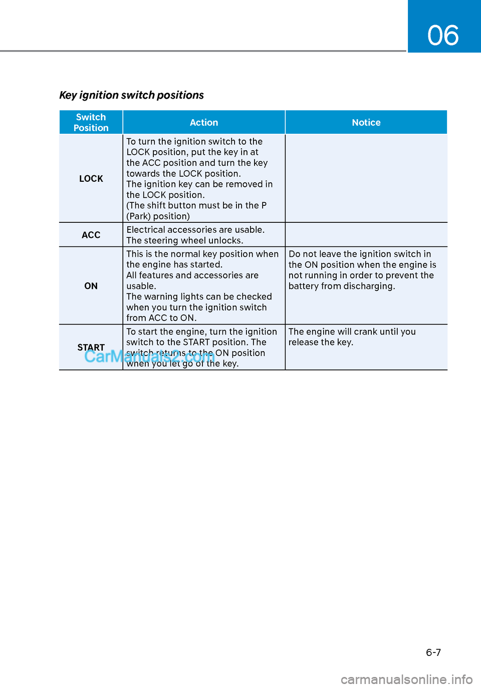
Key ignition switch positions
Switch
Position Action Notice
LOCK T
o turn the ignition switch to the
LOCK position, put the key in at
the ACC position and turn the key
towards the LOCK position.
The ignition key can be removed in
the LOCK position.
(The shift button must be in the P
(Park) position)
ACC Electrical accessories are usable.
The steering wheel unlocks.
ON This is the normal key position when
the engine has started.
All features and accessories are
usable.
The warning lights can be checked
when you turn the ignition switch
from ACC to ON. Do not leave the ignition switch in
the ON position when the engine is
not running in order to prevent the
battery from discharging.
START To start the engine, turn the ignition
switch to the START position. The
switch returns to the ON position
when you let go of the key. The engine will crank until you
release the key.
Page 294 of 537

While Driving6-10
Engine Stop/Start button positions
Button
Position Action Notice
OFF T
o turn off the engine, press the
Engine Start/Stop button with shift
button in P (Park).
When you press the Engine Start/
Stop button without the shift
button in P (Park), the Engine Start/
Stop button does not turn to the
OFF position, but turns to the ACC
position.
ACC Press the Engine Start/Stop button
when the button is in the OFF
position without depressing the
brake pedal.
Electrical accessories are usable. If you leave the Engine Start/Stop
button in the ACC position for more
than one hour, the battery power will
turn off automatically to prevent the
battery from discharging.
ON Press the Engine Start/Stop button
while it is in the ACC position
without depressing the brake pedal.
The warning lights can be checked
before the engine is started. Do not leave the Engine Start/Stop
button in the ON position when the
engine is not running to prevent the
battery from discharging.
START To start the engine, depress the
brake pedal and press the Engine
Start/Stop button with the shift
button in the P (Park) or in the N
(Neutral) position.
For your safety, start the engine
with the shift button in the P (Park)
position. If you press the Engine Start/Stop
button without depressing the brake
pedal, the engine does not start
and the Engine Start/Stop button
changes as follows:
OFF → ACC → ON → OFF or ACC
However, the engine may start if you
depress the brake pedal within 0.5
second after pressing the Engine
Start/Stop button from the OFF
position.
Page 433 of 537

07
7-5
Jump starting procedure
1. Position the vehicles close enough that the jumper cables will reach, but
do not allow the vehicles to touch.
2. Avoid fans or any moving parts in the engine compartment at all times, even
when the vehicles are turned off.
3. Turn off all electrical devices such as radios, lights, air conditioning, etc.
Put the vehicles in P (Park) and set
the parking brakes. Turn both vehicles
OFF.
ODN8A079022ODN8A079022
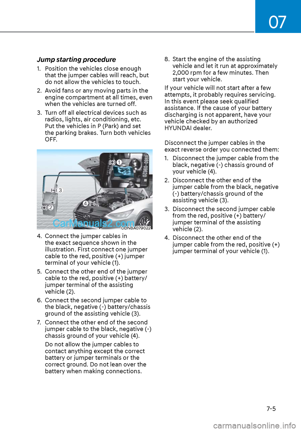
4. Connect the jumper cables in the exact sequence shown in the
illustration. First connect one jumper
cable to the red, positive (+) jumper
terminal of your vehicle (1).
5. Connect the other end of the jumper cable to the red, positive (+) battery/
jumper terminal of the assisting
vehicle (2).
6. Connect the second jumper cable to the black, negative (-) battery/chassis
ground of the assisting vehicle (3).
7. Connect the other end of the second jumper cable to the black, negative (-)
chassis ground of your vehicle (4).
Do not allow the jumper cables to
contact anything except the correct
battery or jumper terminals or the
correct ground. Do not lean over the
battery when making connections. 8. Start the engine of the assisting
vehicle and let it run at approximately
2,000 rpm for a few minutes. Then
start your vehicle.
If your vehicle will not start after a few
attempts, it probably requires servicing.
In this event please seek qualified
assistance. If the cause of your battery
discharging is not apparent, have your
vehicle checked by an authorized
HYUNDAI dealer.
Disconnect the jumper cables in the
exact reverse order you connected them:
1. Disconnect the jumper cable from the black, negative (-) chassis ground of
your vehicle (4).
2. Disconnect the other end of the jumper cable from the black, negative
(-) battery/chassis ground of the
assisting vehicle (3).
3. Disconnect the second jumper cable from the red, positive (+) battery/
jumper terminal of the assisting
vehicle (2).
4. Disconnect the other end of the jumper cable from the red, positive (+)
jumper terminal of your vehicle (1).
Page 448 of 537

Engine Compartment ........................................................................\
............ 8-3
Maintenance Services ........................................................................\
...........8-4
Owner’s Responsibility ........................................................................\
.................... 8-4
Owner Maintenance Precautions ........................................................................\
.... 8-4
Owner Maintenance ........................................................................\
.............. 8-5Owner Maintenance Schedule ........................................................................\
........ 8-5
Scheduled Maintenance Services ................................................................ 8-7Normal Maintenance Schedule (Smartstream G1.6 T-GDi) ...................................8-8
Maintenance Under Severe Usage Conditions (Smartstream G1.6 T-GDi) ......... 8-11
Severe Driving Conditions ........................................................................\
.............. 8-11
Normal Maintenance Schedule (Smartstream G2.5 GDi) ..................................... 8-12
Maintenance Under Severe Usage Conditions (Smartstream G2.5 GDi) ................8-15
Severe Driving Conditions ........................................................................\
..............8-15
Explanation of Scheduled Maintenance Items .......................................... 8-16
Engine Oil ........................................................................\
............................. 8-19
Checking the Engine Oil Level ........................................................................\
........8-19
Checking the Engine Oil and Filter ....................................................................... 8-20
Engine Coolant ........................................................................\
......................8-21Checking the Engine Coolant Level ....................................................................... 8-21
Engine Coolant ........................................................................\
................................ 8-21
Changing Engine Coolant ........................................................................\
.............. 8-23
Brake fluid ........................................................................\
............................ 8-24Checking the Brake Fluid Level ........................................................................\
..... 8-24
Washer Fluid ........................................................................\
......................... 8-25Checking the Washer Fluid Level ........................................................................\
.. 8-25
Air Cleaner ........................................................................\
............................ 8-26Filter Replacement ........................................................................\
......................... 8-26
Climate Control Air Filter ........................................................................\
..... 8-28
Filter Inspection........................................................................\
.............................. 8-28
Filter Replacement ........................................................................\
......................... 8-28
Wiper Blades ........................................................................\
........................ 8-29Blade Inspection ........................................................................\
............................ 8-29
Blade Replacement ........................................................................\
........................ 8-29
Battery ....................................................................\
.......................................8-31For Best Battery Service ........................................................................\
................ 8-32
Battery Recharging ........................................................................\
........................ 8-32
Reset Features ........................................................................\
................................ 8-33
8. Maintenance
8