Page 123 of 557

3-34
Convenient features of your vehicle
To adjust the Zone setting:
1. Determine the desired Zone Number based upon your current
location on the Zone Map.
2. Press and hold the button for 6 seconds, the current Zone
Number will appear on the display.
3. Pressing and holding the button again will cause the numbers to
increment (Note: they will repeat
…13, 14, 15, 1, 2, …). Releasing
the button when the desired Zone
Number appears on the display
will set the new Zone.
4. Within about 5 seconds the com- pass will start displaying a com-
pass heading again.
There are some conditions that can
cause changes to the vehicle mag-
nets, such as installing a ski rack or
a CB antenna. Body repair work on
the vehicle can also cause changes
to the vehicle’s magnetic field. In
these situations, the compass will
need to be re-calibrated to quickly
correct these changes. If you need to recalibrate the com-
pass:
1. Press and hold the button for
more than 9 seconds. When the
compass memory is cleared a "C"
will appear in the display.
2. Drive the vehicle in 2 complete cir- cles at less than 5 mph (8 km/h).
Integrated HomeLink®Wireless
Control System
The HomeLink®Wireless Control
System can replace up to three
hand-held radio-frequency (RF)
transmitters with a single built-in
device. This innovative feature will
learn the radio frequency codes of
most current transmitters to operate
devices such as gate operators,
garage door openers, entry door
locks, security systems, even home
lighting. Both standard and rolling
code-equipped transmitters can be
programmed by following the out-
lined procedures.
Additional HomeLink
®information
can be found at: www.homelink.com
or by calling 1-800-355-3515.
Retain the original transmitter of the
RF device you are programming for
use in other vehicles as well as for
future HomeLink
®programming. It is
also suggested that upon the sale of
the vehicle, the programmed
HomeLink
®buttons be erased for
security purposes.
Page 273 of 557

• When reinstalling your roof anten-na, it is important that it is fully
tightened and adjusted to the
upright position to ensure proper
reception.
When cargo is loaded on the roof rack, do not place the cargo near
the antenna pole to ensure proper
reception.
Shark fin antenna (if equipped)
The shark fin antenna will receive the
AM, FM broadcast signals and trans-
mit data.
Steering Wheel Audio Control
Do not operate multiple audio
remote control buttons simultane-
ously.
VOLUME (VOL + / - ) (1)
Press the VOLUME (+) switch upto increase volume.
Press the VOLUME (-) switch down to decrease volume.
SEEK/PRESET ( / ) (2)
If the SEEK/PRESET switch is
pressed up or down and held for 0.8
second or more, it will function in the
following modes:
RADIO mode
It will function as the AUTO SEEK
select button. It will SEEK until you
release the button.
MEDIA mode
It will function as the FF/RW button.
If the SEEK/PRESET switch is
pressed up or down, it will function
in the following modes:
RADIO mode
It will function as the PRESET STA-
TION UP/DOWN button.
MEDIA mode
It will function as the TRACK UP/
DOWN button.
MODE (3)
Press the MODE button to toggle
through Radio, SXM, or AUX modes.
NOTICE
4-3
Multimedia System
4
OTM049420
OTM048402
Page 396 of 557

5-122
Driving your vehicle
Information
The Smart Cruise Control system
may not operate temporarily due to:
• Electrical interference
• Modifying the suspension
• Differences of tire abrasion or tirepressure
• Installing different type of tires
Information
This device complies with Part 15 of
the FCC rules.
Operation is subject to the following
three conditions:
1. This device may not cause harmful interference, and
2. This device must accept any inter- ference received, including inter-
ference that may cause undesired
operation.
3. Changes or modifications not expressly approved by the party
responsible for compliance could
void the user's authority to operate
the device.
Information
Radio frequency radiation exposure
information:
This equipment complies with FCC
radiation exposure limits set forth for
an uncontrolled environment.
This equipment should be installed
and operated with minimum distance
of 8 in. (20 cm) between the radiator
(antenna) and your body.
This transmitter must not be co-locat-
ed or operating in conjunction with
any other antenna or transmitter.
i
i
iVehicles moving in front of
you with a frequent lane
change may cause a delay in
the system's reaction or may
cause the system to react to a
vehicle actually in an adjacent
lane. Always drive cautiously
to prevent unexpected and
sudden situations from occur-
ring.
Always be aware of the select-
ed speed and vehicle to vehi-
cle distance. The driver
should not solely rely on the
system but always pay atten-
tion to driving conditions and
control your vehicle speed.
The Smart Cruise Control sys-
tem may not recognize com-
plex driving situations so
always pay attention to driv-
ing conditions and control
your vehicle speed.
Page 425 of 557

6-5
What to do in an emergency
6
Information
An inappropriately disposedbattery can be harmful to the
environment and human
health. Dispose of the battery
according to your local law(s)
or regulations.
To prevent damage to your vehicle:
Only use a 12-volt power supply (battery or jumper system) to
jump start your vehicle.
Do not attempt to jump start your vehicle by push-starting.
Jump starting procedure
1. Position the vehicles close enough that the jumper cables will reach,
but do not allow the vehicles to
touch.
2. Avoid fans or any moving parts in the engine compartment at all
times, even when the vehicles are
turned off.
3. Turn off all electrical devices such as radios, lights, air conditioning,
etc. Put the vehicles in P (Park)
and set the parking brakes. Turn
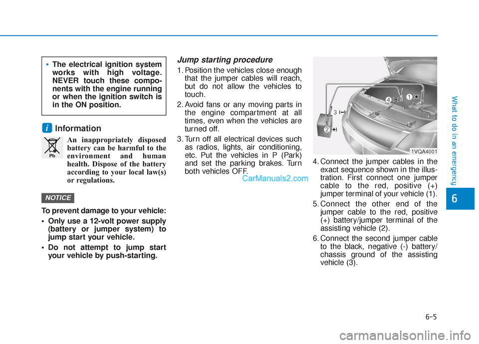
both vehicles OFF. 4. Connect the jumper cables in the
exact sequence shown in the illus-
tration. First connect one jumper
cable to the red, positive (+)
jumper terminal of your vehicle (1).
5. Connect the other end of the jumper cable to the red, positive
(+) battery/jumper terminal of the
assisting vehicle (2).
6. Connect the second jumper cable to the black, negative (-) battery/
chassis ground of the assisting
vehicle (3).
NOTICE
i
Pb
The electrical ignition system
works with high voltage.
NEVER touch these compo-
nents with the engine running
or when the ignition switch is
in the ON position.
1VQA4001